1
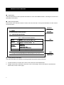
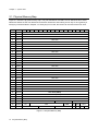
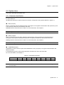
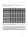
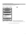
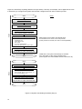
SYSTEM LSI Dual Interface RFID MN63Y1208-E1 Administrator's Manual < non NDA type > Ver. 1.1 Warning and Precaution Regarding to Use of the Technical Information and Semiconductor Described in This Document (1) In case of providing non-resident with, or exporting the product and technical information described in this document, please comply with the law of the interested state, especially, the law regarding to security export management. (2) The technical information described in this document describes the representative characteristic of the product and the examples of application circuit, etc, which is not licensed by the intellectual property right or other rights of our company or other companies. Therefore, in case there is any problem arising from the use of said technical information regarding to the property right of a third party, our company should be exempted from any responsibility concerned. (3) The product described in this document is purposed for its standard usage – common electronic equipment (business equipment, communication equipment, measurement equipment, home electric appliances, etc). For the customer who considers a special usage – the usage which requires a special quality, liability, might harm human body, that any failure or malfunction might directly threaten human life (for the use of aviation/universe, traffic tools, burning appliances, life support system, safety apparatus, etc) and the customer who considers a usage except for the standard purposed by our company, please have a discussion with the sales contact window of our company in advance. Otherwise, we will not be liable for any defect which may arise later in your equipment. (4) We appreciate your understanding in case of no advance notice before any change for the improvement, etc of the product and the specification of the product described in this document, due to which, please request to get and confirm the latest written standards and specification sheet of the product in advance when doing final design, purchasing and using it. (5) When doing design, please use it within the scope of absolute maximum rating, operation guarantee condition (operating power voltage, operating environment, etc). Please make a full discussion to make sure that it will not go beyond the transient state when setting power on/off, switching among all kinds of modes. In case of use under the status beyond guaranteed performance, our company will not be responsible for any failure, or defect of the equipment which might happen later. In addition, please figure out a systematic countermeasure such as redundancy design, flame propagation countermeasure design, malfunction proof design, etc to prevent the equipment in use from causing physical injury, fire accident, public loss arising from the operation of the product made by our company by considering the failure occurrence rate, failure mode normally estimated regarding to semiconductor product even if in case of the use within guaranteed performance. (6) In order to prevent failure and variation of characteristic arising from the foreign factors (ESD, EOS, thermal stress, mechanical stress) during the process of customer, or when handling, mounting the product, please keep to the described content of precaution items regarding to use. In addition, regarding to the product to which moisture-proof packaging is necessary, please keep to the conditions determined when concluding every specification sheet, such as retention period, length of exposure after being unsealed, etc. (7) We will stiffly refuse the reprint or copy of all or a part of this document without the written authorization of our company. 20100202 Please feel free to contact our sales office or sales department at the end of the document for any inquiries regarding this document and the semiconductor of our company. PanaXSeries is a registered trademark of Panasonic Semiconductor Solutions Co., Ltd. The other corporation names, logotype and product names written in this book are trademarks or registered trademarks of their corresponding corporations. About this manual ■ Organization These specifications provide important information for users of the MN63Y1007E1, including an overview and descriptions of functions. ■ Manual Configuration Each section of this manual consists of a title, main text, and notes. The layout and definition of each section are shown below. Middle title 1.1 UART Small title This section describes the UART specification. 1.1.1 Communication Specifications Table 1-1 shows the UART specification of this RFID. Table 1-1 UART Communication Specification Data transfer method Data rate Asynchronous, half-duplex (Only IRQ notification allows fullduplex) DUMMY 1200 bps, 2400 bps, 4800 bps, 9600 bps, 19200 bps, 38400 bps Character transmission LSB-first Data (8 bits) Start bit (1bit) Parity bit (1bit, even) Stop bit (1bit) See Note below. Other No flow control signal (RTS/CTS) Note: In order to ensure the timing margin, when sending consequtive data from the host, use a 2-bit stop bit or set the interval between stop bit and next start bit to 1 bit or more. ■ Text Note This is the Note. Please read. Finding Desired Information This manual provides two methods for finding desired information quickly and easily. 1. Consult the table of contents at the front of the manual to locate desired titles. 2. Chapter names are located at the top outer corner of each page, and section titles are located at the bottom outer corner of each page. 4 Chapter 1 Overview Chapter 2 System Area Chapter 4 Cipher Functionality Chapter 5 Error Code Chapter 6 Annex 1 2 3 4 5 Contents Chapter 1 Overview ................................................................... 7 1.1 Overview............................................................................................................................8 Chapter 2 System Area ............................................................. 9 2.1 Physical Memory Map .....................................................................................................10 2.2 System Area .....................................................................................................................11 2.2.1 Parameter Specification .............................................................................................11 2.2.2 Parameter Application Timing ..................................................................................15 Chapter 3 Cipher Functionality ............................................ 1716 Chapter 4 Error Code .......................................................... 1919 4.1 Error Code ...................................................................................................................2020 4.1.1 JISX6319-4 ............................................................................................................2020 4.1.2 ISO/IEC14443 TypeB ...........................................................................................2020 4.1.3 Serial Interface (I2C) .............................................................................................2020 Chapter 5 Annex .................................................................. 2121 5.1 Configuring the System Area ......................................................................................2222 5.1.1 Precautions ............................................................................................................2222 5.1.2 Setting Procedures of System Area .......................................................................2323 6 Chapter 1 Overview 1 Chapter 1 Overview 1.1 Overview This is a manual for the administrator of the dual interface RFID (Radio Frequency Identification) LSI MN63Y1208, and describes the following: ■ System area (Chapter 2) Describes the information on security in the system area of FeRAM, which is omitted in the User's Manual. ■ Cipher functionality (Chapter 3) Provides the cipher functionality (encryption, authentication) that uses AES. ■ Additional error codes (Chapter 4) Provides the error codes related to the Administrator's Manual, which are not described in the User's Manual. ■ Annex (Chapter 5) Describes examples of configuring the system area in the manufacturing process. 8 Overview Chapter 2 System Area 2 Chapter 2 System Area 2.1 Physical Memory Map Figure 2-1 shows the physical memory map. The part indicated in bold italic is to be defined in this manual. Blocks 25 and 26 are the user area and can be also used as the area storing secrec key for encryption by a family key to be described in Chapter 4. If family key is not used, the blocks can be used as the user area. Block Address 0x0 0x1 0x2 0x3 0x4 0x5 0x6 0x7 0x8 0 0x0000 User Area 1 0x0010 User Area 2 0x0020 User Area 3 0x0030 User Area 4 0x0040 User Area 5 0x0050 User Area 6 0x0060 User Area 7 0x0070 User Area 8 0x0080 User Area 0x9 9 0x0090 User Area 10 0x00A0 User Area 11 0x00B0 User Area 12 0x00C0 User Area 13 0x00D0 User Area 14 0x00E0 User Area 15 0x00F0 User Area 16 0x0100 User Area 17 0x0110 User Area 18 0x0120 User Area 19 0x0130 User Area 20 0x0140 User Area 21 0x0150 User Area 22 0x0160 User Area 23 0x0170 User Area 24 0x0180 User Area 25 0x0190 User Area (EEFK) 26 0x01A0 User Area (EEMK) 27 0x01B0 EEK 28 0x01C0 EMK 29 0x01D0 30 0x01E0 31 0x01F0 COUNTER SC Physical Memory Map 0xC ROSI 0xD 0xE 0xF MC PMM SECURITY Figure 2-1 Physical Memory Map 10 0xB CFEN IDM RORF 0xA AFI FWI TNPRM HW2 HW1 SL BCC Chapter 2 System Area 2.2 System Area This section describes the system area. 2.2.1 Parameter Specification This section provides parameters for security in the system area. For information about other parameters, see the User's Manual. All addresses and block numbers used in this section correspond to the physical address in Figure 2-1. ■ EEK (16 bytes) EEK is a secret key used for data encryption or decryption in encrypted communication with private key, and is encrypted by master key and stored in this area. Reading this area causes all-0 to be read. For more information, see Chapter 4. When writing data to this parameter, use data for EEK only. For more information, see Table 4-7. ■ EMK (16 bytes) EMK is a secret key used for MAC (Message Authentication Code) generation and authentication in encrypted communication with private key, and is encrypted by master key and stored in this area. Reading this area causes all-0 to be read. For more information, see Chapter 4. Note: When writing data to this parameter, use data for EMK only. For more information, see Table 4-7. ■ COUNTER (8 bytes) COUNTER is a value used as a part of the initialization vector (16 bytes) in encrypted communication with READ command. In manufacturing process, when writing the Block 29 data to this area, write all-0 data. For more information, see Chapter 4. Table 2-1 COUNTER Parameter Address COUNTER 0x01D0 0x01D1 0x01D2 0x01D3 0x01D4 D0 D1 D2 D3 D4 0x1D5 0x1D6 0x01D7 D5 D6 D7 Note: This RFID increases the COUNTER value every time it receives a READ command in encrypted communication. System Area 11 Chapter 2 ■ System Area CFEN (4 bytes) As with BCC, CFEN is a flag data to validate the setting values in the system area of FeRAM. Table 2-2 shows the valid setting values for system area. Until valid values are written to CFEN and BCC, default values (implemented in hardware) are used for each parameter. For information about the default values, see Section 3.3 in the User's Manual and the descriptions for each parameter in this section. Table 2-2 Valid CFEN Setting Values for System Area Address 0x01D8 0x01D9 0x01DA 0x01DB System area enable setting 0x01 0x23 0x45 0x67 Note: For EEK, EMK, and COUNTER, no default values are provided and the system area values of FeRAM are used regardless of CFEN settings. Note: In order to enable the written flag data, the RFID's power supplies (both VDDEX and the supply from RF interface) must be turned off once after writes. The data will be enabled after next power-on. Note: Before writing valid setting values to CFEN, write the given setting values to each parameter in the system area of FeRAM. (Default values for each parameter are implemented in hardware.) ■ MC (4 bytes) MC is a data to control the internal modes of this RFID. In manufacturing process, when writing the Block 29 data to this area, write the data shown in Table 2-3. Table 2-3 MC Setting Values Address System area enable setting 12 System Area 0x01DC 0x01DD 0x01DE 0x01DF 0x89 0xAB 0xCD 0xEF Chapter 2 ■ System Area SL (1 byte) SL is a flag data to lock the system area. Table 2-4 shows the SL settings and corresponding values. Setting the SL to MODE1 or MODE2 allows to lock the write operation to parameters of the system area. By default, the SL is set to 0x00 (MODE0). Table 2-4 SL Settings and Corresponding Values Mode MODE0 Setting value (Address: 0x01FE) MODE1 0x00 MODE2 0x0F 0xFF Interface to be accessed RF Serial RF Serial RF Serial EEK *) R/W R/W RO RO RO RO EMK *) R/W R/W RO RO RO RO COUNTER R/W R/W RO RO RO RO CFEN R/W R/W RO RO RO RO MC R/W R/W RO RO RO RO SC R/W R/W RO RO RO RO IDM R/W R/W RO RO RO RO PMM R/W R/W RO RO RO RO AFI R/W R/W RO RO RO RO FWI R/W R/W RO RO RO RO HW1 R/W R/W RO RO RO RO RORF R/W R/W RO R/W RO RO ROSI R/W R/W RO R/W RO RO SECURITY R/W R/W RO R/W RO RO TNPRM R/W R/W RO R/W RO RO HW2 R/W R/W RO R/W RO RO SL R/W R/W RO R/W RO RO R/W R/W RO BCC *) All-0 is always read. R/W RO RO R/W: Read/Write, RO: Read Only In addition, Figure 2-2 illustrates the state transition diagram between system lock modes. Writing 0x0F to SL allows to transition from MODE0 to MODE1. Writing 0xFF to SL allows to transition from MODE0 or MODE1 to MODE2. The transition from MODE2 to MODE1 is disabled. Note: SL is the flag data for locking the system area. In order to release the system area that was once locked, dedicated command using the serial The disclosure of this dedicated command, NDA is required. System Area 13 Chapter 2 System Area MODE0 Write 0xFF to SL Write 0x0F to SL MODE1 MODE2 Write 0xFF to SL It cannot change from mode1 to mode0. It cannot change from mode2 to mode0 or mode1. Figure 2-2 State Transition Diagram between System Lock Modes ■ BCC (1 byte) BCC is a flag data to validate the setting values in the system area of FeRAM. Table 2-5 shows the valid setting value for system area. Until valid values are written to BCC and CFEN, default values (implemented in hardware) are used for each parameter. For information about the default values, see Section 3.3 in the User's Manual and the descriptions for each parameter in this section. Table 2-5 Valid BCC Setting Value for System Area Address 0x01FF System area enable setting BCC setting value BCC setting value is obtained by adding the values at 0x01D8 to 0x01EF and 0x01FC to 0x01FE of the system area, byte-by-byte, to the default value 0x00 of 1 byte and subtracting the lower one byte of the calculation result from 0x100. BCC is calculated by hardware at power-on of this RFID or at a reset. If the calculation result generates an error, this LSI operates with default values for each parameter and the error state can be read with a response to the RREG command in serial communication. 14 System Area Chapter 2 System Area 2.2.2 Parameter Application Timing Table 2-6 lists the setting application timings after rewriting parameters in the system area while CFEN is enabled. Table 2-6 Parameter Application Timing A timing at which new parameter setting is applied after rewriting parameters while CFEN is enabled. EEK Apply immediately after rewrites. EMK Apply immediately after rewrites. COUNTER Apply immediately after rewrites. CFEN MC SL BCC Apply after turning power ON from OFF following rewrites. Apply after turning power ON from OFF following rewrites. Apply after turning power ON from OFF following rewrites. Apply after turning power ON from OFF following rewrites. Note: Power OFF means power supplies from both VDDEX and RF interface are OFF. System Area 15 Chapter 3 Cipher Functionality 3 Chapter 4 Error Code 4 Chapter 4 Error Code 4.1 Error Code This section provides the error codes related to this Administrator's Manual by interface, which are not described in the User's Manual. 4.1.1 JISX6319-4 Table 4-1 lists the meanings of statuses for JISX6319-4, which are not described in the User's Manual. Table 4-1 Status Flag Status flag 1 Status flag 2 Meaning 0xFF 0xA2 Block count specification error 0xFF 0x60 Description Self-diagnosis error When writing to EEK and EMK, the data size was other than 16 bytes. MAC verification error occurred in encryption WRITE command processing. Data was written over EEK and EMK. Write access to the system area (SL function) was performed while the system is locked. 4.1.2 ISO/IEC14443 TypeB Table 4-2 lists the meanings of statuses for ISO/IEC14443 TypeB, which are not described in the User's Manual. Table 4-2 Status Word SW1 SW2 Meaning Description 0x67 0x00 Lc/Le specification error When writing to EEK and EMK, the data size was other than 16 bytes. MAC verification error occurred in encryption WRITE command processing. 0x6F 0x00 Self-diagnosis error Data was written over EEK and EMK. Write access to the system area (SL function) was performed while the system is locked. 4.1.3 Serial Interface (I2C) Table 4-3 lists the meanings of statuses for serial interface (I2C), which are not described in the User's Manual. Table 4-3 Status Value Meaning Description When writing to EEK and EMK, the data size was other than 16 bytes. 0x26 Command parameter error Write access to the system area (SL function) was performed while the system is locked. Data was written over EEK and EMK. 20 Error Code Chapter 5 Annex 5 5.1 Configuring the System Area When configuring the system area in the manufacturing process, you must follow some precautions. This section describes the precautions and the setting procedures. 5.1.1 Precautions Precautions are as follows: 1: When configuring the system area by using a contactless reader/writer while the contactless reader/writer turns carrier off every time a command is issued, it is necessary to observe the writing unit and order. For example, the parameters (e.g., SC, IDM) related to communication command can change their values when configuring the system area or when writing a valid value to CFEN (*). In this case, when writing a valid value to CFEN, writing data to Blocks 29 to 31 by a single command prevents the system area setting from being complicated. 2: Data must be written to EEK (Block 27) and EMK (Block 28) each in units of one block. Use a WRITE command to write a block (16 bytes) of plaintext. 3: All-0 is always read from EEK (Block 27) and EMK (Block 28), regardless of the value of written data. When verifying data writes to these blocks, check if the RFID responds normally to the encryption WRITE command. (*) As an example, we assume that data is written to Blocks 29 and 30 in units of one block while the contactless reader/writer turns carrier off every time a command is issued. ● Description (1) Writing to Block 29: Write a valid value to CFEN (CFEN has invalid value before executing (1)). (2) Writing to Block 30: Write a given value to IDM. When data is written in the order of (1) and (2), the value of IDM changes as follows. Before executing (1): default value (0x02FE000000000000); After executing (1): the value of FeRAM that is not written is set since (2) has not yet been executed. Whe using READ and WRITE commands based on JISX6319-4, IDM must be specified. Although you can acquire the IDM of this RFID using a REQ command, it is necessary to insert a REQ command between (1) and (2) to acquire IDM and set that IDM to the IDM to which a value is to be written by a WRITE command in (2). When writing a valid value to CFEN, it is recommended to use a single WRITE command for Blocks 29 to 31. 22 5.1.2 Setting Procedures of System Area This section provides two setting procedures of the system area (Steps 1 and 2). Figure 5-1 shows Step 1 (writing all data only in one process). Notes Start Write to EEK (Block 27) Use a WRITE command of 1 block (16 bytes). Write to EMK (Block 28) Use a WRITE command of 1 block (16 bytes). Verify the writes to EEK and EMK Check if the RFID responds normally to the encryption WRITE command. Write to system area Use a WRITE command of 3 blocks. ・COUNTER: All-0 ・CFEN, MC: Enable ・MC: Enable ・SL: Lock state (Mode1 or 2) ・Other (SC, IDM, HW, etc.): Given states Verify the write to system area Use a READ command of 3 blocks to check whether to match the written data. End CFEN, BCC, and system area settings are enabled from next power-on after power-off (that means power supplies from both VDDEX and RF interface are off). Figure 5-1 System Area Setting Procedure (Step 1) 23 Figure 5-2 shows Step 2 (writing all data in two processes). This step, for example, can be applied to the case in which first you configure the system area and then configure the user area in another process. Start Notes Write to EEK (Block 27) Use a WRITE command of 1 block (16 bytes). Write to EMK (Block 28) Step 1 Use a WRITE command of 1 block (16 bytes). Verify the writes to EEK and EMK Check if the RFID responds normally to the encryption WRITE command. Write to system area (Blocks 29 to 31)[1] Use a WRITE command of 3 blocks. ・COUNTER: All-0 ・CFEN, MC: Enable ・MC: Enable ・SL: Unlock state (Mode0) ・Other (SC, IDM, HW, etc.): Given states When writing to the system area several times, SL should be set to “Lock” in the final process. (In the process on the left, SL is set to “Unlock (Mode0).” Verify the write to system area [2] Use a READ command of 3 blocks to check whether to match the written data. CFEN, BCC, and system area settings are enabled from next power-on after power-off (that means power supplies from both VDDEX and RF interface are off). End Start Write to user area & Verify the write Step 2 Write to system area (Block 31)[2] Use a WRITE command of 1 block. ・Specify RORF, ROSI, and SECURITY, etc. ・SL: Lock state (Mode1 or 2) Verify the write to system area[2] Use a READ command of 1 block to check whether to match the written data. End Figure 5-2 System Area Setting Procedure (Step 2) 24 Revision History Revised on May 16, 2013 Purpose - Version 1.0 Page - Version xx Section Comments Initial edition Page - Section - Comments - Revised on Jul 18, 2014 Purpose Add Version 1.0 Page Section - - Version 1.1 Comments - Page Section P13 - Comments Add Note, “SL is flag data for locking the system area…” MN63Y1208-E1 Administrator's Manual Jul. 18, 2014, Version 1.1 Issued by Panasonic Semiconductor Solutions Co., Ltd. Edited and produced by Panasonic Semiconductor Solutions Co., Ltd. © Panasonic Semiconductor Solutions Co., Ltd. 2014