1
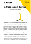
User manual
For RUD-ICE-lifting chains
in Grade 120
Certified by the BG (Employers Liability Insurance
Association)
Metal North South Technical Committee Metal
and surface treatment Certificate Authority
in BG PZNM
Translation of the
Original instructions
According to EG-Machinery Directive 2006/42/EG,
EG material use directive and BGR 500 / DGUV 100-500 chapter 2.8, EN 818, EN 1677.
1
Determined usage for lifting and
transportation of loads
1.
Selection of lifting chains
1.1 Weight
1.4 Asymmetrical loads
The weight of the load must be known.
1.2
Centre of gravity
The centre of gravity of the load must be known.
1.3 Method of lifting
For multiple leg lifting the inclination angle should
be chosen between 15° and 60°. Inclination angles
exceeding 60° create overloading of the lifting chain,
inclination angles under 15° can lead to instability of
the load. When using choke hitches, the WLL must
be reduced to 80 % of the indicated WLL.
In applications using a 4-leg sling there is always the
danger that only the 2 diagonally opposite legs are
load bearing, even when the load is symmetrical!
1-leg
If one leg must be shortened in multiple leg application, this could be an indication for an uneven load,
which should be verified by a competent person. Acc.
to BGR 500 / DGUV 100-500 section 2.8, the WLL for
single fall becomes valid when unsymmetrical load
occurs at a multiple strand sling.
1.5WLL
WLL in tons at symmetrical loading (see table):
2-leg
3- and 4-leg
endless
chain sling in
choke hitch
Diameter of the
lifting chain in mm
Inclination angle ß
load factor
Ø 4
Ø 6
Ø 8
Ø 10
Ø 13
Ø 16
endless
0°
1
0.8
1.8
3.0
5.0
8.0
12.5
0-45°
1.4
1.12
2.5
4.25
7.1
11.2
17.0
>45-60°
1
0.8
1.8
3.0
5.0
8.0
12.5
0-45°
2.1
1.7
3.75
6.3
10.6
17.0
26.5
>45-60°
1.5
1.18
2.7
4.5
7.5
11.8
19.0
1.6
1.25
2.88
4.8
8.0
12.8
20.0
Acc. to BGR 500 / DGUV 100-500 section 2.8, the WLL for single fall
becomes valid when unsymmetrical load occurs at a multiple strand sling.
For lower or higher WLL up to 126 t, please select
the most suitable chain designed from the VIP-10
Program!
RUD ICE-120-Chains and components are designed in accordance with DIN EN 818 and 1677
and withstand a dynamic loading of more than
20,000 load cycles.
2
The BG recommends: when there is high dynamic application and a permanent operation, the
bearing stress must be reduced according to
Mechanism group 1Bm (M3 according to DIN EN
818-7), e.g. by using a larger chain diameter.
endless chain
Diameter of the
lifting chain in mm
Inclination angle ß
load factor
Ø 4
Ø 6
Ø 8
Ø 10
Ø 13
Ø 16
Temperatur
°C
1.6 single
0-45°
>45-60°
1.1
0.8
0.88
0.64
2.0
1.44
3.3
2.4
5.5
4.0
8.8
6.4
14.0
10.0
choke hitch
double
0-45°
>45-60°
1.7
1.2
1.36
0.96
3.1
2.1
5.1
3.6
8.5
6.0
13.6
9.6
21.2
15.0
single
0°
0.8
0.64
1.44
2.4
4.0
6.4
10.0
double
0-45°
>45-60°
1.1
0.8
0.88
0.64
2.0
1.44
3.3
2.4
5.5
4.0
8.8
6.4
14.0
10.0
Acc. to BGR 500 / DGUV 100-500 section 2.8, the WLL for single fall
becomes valid when unsymmetrical load occurs at a multiple strand sling.
When using lifting chains at temperatures beyond 200°C (refer to page 4),
the permissible WLL has to be reduced. Working load in % at chain temperature of:
-60 up to +200°C
100 %
obove 200 up to 250°C
90 %
Assembly set, clevis connection
quality grade 120 (ICE)
ICE-Masterlinks are equipped with a weld-in free
moveable clevis connector.
The outcome of this is a “foolproof” connection regarding the chain diameter and the number of legs.
The masterlink also offers an identification tag with
an integrated gauge function.
The connecting- and the securing pin are already
pre-assembled.
The RUD-system consisting of ICE-Clevis connection
and the oval load pin are making the assembly easy.
The RUD-ICE clevis connection system provides by
the dimensioning and the foolproof system necessarily the correct allocation of the correct ICE nominal
chain diameter.
Clevis width X avoids assembly of a bigger chain.
Pin diameter dimension Y avoids the assembly of a
smaller chain.
Only the correct ICE chains and the corresponding
ICE-parts of the same nominal diameter are supposed to be assembled.
obove 250 up to 300°C
60 %
FOOL PROOF SYSTEM
Attention:
- ICE quality grade 120:
Only chains, components
and connecting pins which
are embossed with ICED1-12 must be used.
- Sleeve pin for the securing of
the load pin must be installed
with the groove showing to
the outside.
- Use sleeve pin only once.
- Use only original RUD-ICE
spare parts
The assembly of chains and components
from different manufacturers is not allowed!
= Identification of the complete assembled
chain slings.
= this mark confirms that the technical
requirements of the European Directives
are fulfilled.
Please note the following regulations:
EN 818-1, EN 88-2, EN 818-4, EN 1677, BGR
500 / DGUV 100-500 chapter 2.8 and the
corresponding country-specific regulations.
We do not take any responsibility for damage occurred by non-conformance of these standards,
regulations and hints!
3
Assembly-system with IC
ICE-UNIVERSAL-SYSTEM
Universal coupler system, chains and components
are not foolproof by using the ICE-Connector.
When assembling and repairing, it is necessary to
pay particular attention that the chains, master links
and components are of the same nominal size!
The nominal size and number of legs stamped
on the master link must be observed during
assembly!
Attention:
- Use retaining pins only once!
- Identification must be correct!
- Use only original spare parts!
- Do not mix with chains and components from
other quality classes, e.g. VIP or Grade 80!
Chain 10 mm
1-leg
Example:
NON FOOL PROOF SYSTEM!!!
2
Usage for lifting chains
When using lifting chain assemblies, attention must be
paid according to the regulations BGR 500 / DGUV 100500, chapter 2.8 “Betreiben
von Lastaufnahmeeinrichtungen im Hebezeugbetrieb”
or other specific country
statutory regulations (out of
Germany). Whenever it is possible leave the danger
zone. Never leave lifted loads unattended.
Be sure before the first lift that:
- the chain assembly corresponds to the ordered
ones
- the test certificate of the factory approval (form
EN 10204 with the details from EN 818-4) and
declaration of conformity is present
- the details marked on the identification tag of the
assembly correspond to the specification on the
test certificate and the declaration of conformity
- the details are registered in the chain card file. This
documentation should include a description of the
chain assembly, as well as the proof of identity
(test certificate resp. declaration of conformity ref.
no.).
4
1/10
2/8
1.7
Chain 8 mm
2-leg
A failure to follow the
assembly instructions
can lead to personal and
material damage!
2.1 Handling
Lifting chains must be used with straight legs without
twists, knots or breaks. Load hooks must not be tip
loaded and must be equipped with safety latches to
avoid unintentional unloading.
Before the usage of hooks without a safety latch a
risk assessment has to be carried out and the whole
operation must be made extra careful. When using
chain shorteners DIN 5692:2011-4 must be observed
in regard to the technical requirements.
Master links must be free moveable at the bowl of
the crane hook.
Before hanging the non fool proof masterlink into
the crane hook, the ICE-Connectors and the ICE
Shorteners must be positioned in such a way that
they are located underneath the flattend zone of the
masterlink before loading.
When components are modified by the user, the
health and safety requirements must be amended
and the risk assessment must be anewed and
corresponding actions carried out.
Avoid shock loading. Sharp edges are bending or
damaging chain links and components. In this case
use either edge protection, next bigger chain size or
reduce the WLL by 20 %.
ICE-AGH Application
Close IAGH manually
2.2
2.3
Locking lever up
= IAGH is locked
Locking lever puseg down
= IAGH can be opened
Multi – leg sling chains where not all individual legs are used
Application of the
lifting means
Number of individual
used legs
Load factor for
the nominal WLL
2-leg
3- and 4-leg
3- and 4-leg
1
2
1
1/2
2/3
1/3
Storage of sling chains
Sling chains should be stored on racks in hanging
conditions.
5
2.4 Influences of high and low
temperature
If sling chains are used in temperatures ranging
from 200°C upwards (e.g. in hot environments such
as steel production, forges, foundries etc.) the WLL
has to be reduced according to the following table.
°C
%
-60° up to +200°C
100 %
With temperatures under -60°, the ICE-lifting chains
must not be used.
Temperatures ranging from 300°C upwards are not
allowed.
Reduced WLL in % where the chain slings reaches
temperatures of:
above 200° up to 250°
90 %
above 250° up to 300°
60 %
The special fluorescent ICE-pink powder coating
signals permanently the maximum temperature at
which the ICE chain had been used. Once pink
colour changes into brown-black, ICE chains
must be replaced or sent back to manufacturer for
inspection. (The pink colour changes to brownblack when the chain is used in temperature
areas higher than 300°C.)
2.5
Chemical influences
Sling chains of ICE special quality 12 must not be
used under chemical influences (acids, alkaline
solutions and vapors), e.g. in pickling baths or hot
dip galvanizing plants. Attention should be paid to
special instructions such as BGR 150 / DGUV 109004 or other country specific statutory regulations.
3
Inspection and test
3.1
Visual and function test
For controlling sling chains,
regular inspection by an expert have to be carried out
within a period of 12 months.
Depending on the conditions
of use, e.g. permanent usage,
increased wear or corrosion,
the inspection needs to be
carried out earlier. The expert
has to record the examination in the chain card file.
Protocols of tests and any other records have to be
kept. Should any of the following damage occur,
the sling chain should immediately be taken out for
maintenance and service:
6
2.6
Other influences
Before using sling chains in chemicals, the manufacturer must be contacted first regarding the concentration, period of penetration and temperature of use.
a) The identification tag is unreadable or the tag is
missing.
b) Twisting, deformation and breakage of chains,
components and master links.
c) Lengthening of the chain by plastic deformation
of individual links by more than 5 % referred to the
pitch of 3d.
Max. allowed wear on the ICE oval bolt: 15 %
d) Wear occurs at the chain links caused by abrasion
on the outside and at chain the interlink zone.
dm = average link width
d1/d2 = actual sizes
d = nominal size
For measuring the wear with a calliper, the chain
must be loose. A wear up to 10 % (dm) is permissible.
e) Cuts, notches, grooves, failure, increased corrosion, discolouring due to heat, bent or twisted chains
and components. Especially deep notches in the
tensile strength region and sharp-edged notches in
lateral direction are not allowed.
f) The width of the (hook) mouth must not exceed
10 % of the nominal value.
See embossed markings and
maximum measuring value
Fmax.
The safety latch must slip
into the hook tip in order to
occur from closure. Carefully
examine bowl of the hook in
regard of notches.
4
3.2 Examination for cracks
Inspections going further than just visual checking, the
corresponding national regulations have to be fulfilled.
RUD recommends, respectively to BGR 500 / DGUV
100-500 chapter 2.8, to do a crack test inspection at
least after 3 years.
A proof load test for chains and components is insufficient because cracks can only be recognized with
a magnetic crack test.
Testing wear
of nominal
diameter
Testing plastic elon- Testing pitch
gation
elongation
caused by
caused by
overloading
wear of
nominal diameter
ICE Identification tag with integrated chain
testing gauge
- the patented idea-
Repair and Maintenance
Repair works have only to be done by experts, disposing the knowledge and skills required. Components and chains with failures, being bent, twisted
and considerably deformed must be exchanged.
With the chain, the complete leg has to be replaced. Minor faults such as notches and grooves
have to be grind off carefully (to avoid notch effect). The cross section of the material must not be
decreased by more than 10 % Welding on chains
and components is forbidden.
Maximum allowed wear of pin diameter = 15 %.
Fundamentally, use new connecting bolts and tensioning
sleeves when changing these
parts! Use only original RUD
spare parts! It is only allowed
to connect ICE chains with ICE
components (stamped with
“ICE”).
All carried out repairings must
be documented in the chain card file resp. if RUD-IDNet® is used, make notes in the database.
It is not allowed to combine ICE chains and
components from other manufacturers!
7
5Documentation
Chain card file
The chain card file contains the continuous history
of a chain sling. The contents are: first record (paragr. 2), inspection/test dates (paragr. 3) as well as
repair and maintenance (paragr. 4). If there are any
repairs, the reason must be indicated. The records
in the chain card file give proof on steady supervision measurements of the user during the use of
the sling chains.
Carefully adhere to statutory requirements and
the approval code of practise issued by the trade
association.
Our test personnel are well educated specialists
according to EN 473 working with the most modern
equipement. Test certificate according to BGR 500
/ DGUV 100-500 as well as actual EU law. Testing
equals safety and keeps the value added.
The RUD inspection service offers you the complete
safety service directly on the field.
We are testing every lifting mean according to the
beside mentioned 6 points safety program.
Service-Telefon: 0049 7361/504-1351
RUD Ketten
Rieger & Dietz GmbH u. Co. KG
73428 Aalen
Tel. +49 7361 504-1351-1370-1262
Fax +49 7361 504-1460
[email protected]
www.rud.com
REGISTRATION
VISUAL CONTROL
CRACK TESTING
MAINTENANCE
CERTIFICATION
HinT
It is not allowed to combine ICE-chains
and components with chains and components quality class 8 or 10.
5.2RUD-ID-NET®Applikation
The ICE-components will
be equipped with a RUDID-Point® and can clearly be
related by the identification number. This number
can be determined with the RUD-ID-EAS-CHECK®
readers and data can be transferred into the RUDID-NET®-Application.
The application will support your product administration and documentation.
For further information please go to the RUD webpage or ask your RUD authorized distributor.
EG-Konformitätserklärung
EC-Declaration of conformity
entsprechend der EG-Maschinenrichtlinie 2006/42/EG, Anhang II A und ihren Änderungen
According to the EC-Machinery Directive 2006/42/EC, annex II A and amendments
Hersteller:
RUD Ketten
Rieger & Dietz GmbH u. Co. KG
Manufacturer:
Friedensinsel
73432 Aalen
Hiermit erklären wir, dass die nachfolgend bezeichnete Maschine aufgrund ihrer Konzipierung und Bauart, sowie in der von uns in Verkehr gebrachten Ausführung, den grundlegenden Sicherheits- und Gesundheitsanforderungen der EG-Maschinenrichtlinie
2006/42/EG sowie den unten aufgeführten harmonisierten und nationalen Normen sowie
technischen Spezifikationen entspricht.
Bei einer nicht mit uns abgestimmten Änderung der Maschine verliert diese Erklärung ihre
Gültigkeit.
Produktbezeichnung:
Anschlagkettengehänge Gk12 ICE
_____________________________________________
ND
4-16 mm, verkürzbar und unverkürzbar
_____________________________________________
Folgende harmonisierten Normen wurden angewandt:
EN 12100 : 2011-03
_________________
EN
1677-2 : 2008-06
_________________
EN 1677-4 : 2009-03
_________________
EN 818-2 : 2008-12
_________________
EN 818-6 : 2008-12
_________________
EN 1677-1 : 2009-03
_________________
EN 1677-3 : 2008-06
_________________
EN 818-1 : 2008-12
_________________
EN 818-4 : 2008-12
_________________
_________________
Folgende nationalen Normen und technische Spezifikationen wurden außerdem angewandt:
BGR 500, KAP2.8 : 2008-04
_________________
DIN
15429 : 1978-07
_________________
DIN 5692 : 2011-04
_________________
_________________
_________________
DIN 15428 : 1978-08
_________________
DIN 5688-3 : 2007-04
_________________
PAS 1061 : 2006-04
_________________
_________________
_________________
Für die Zusammenstellung der Konformitätsdokumentation bevollmächtigte Person:
Reinhard Smetz, RUD Ketten, 73432 Aalen
Aalen, den 09.05.2014
8
MEASURING
Dr.-Ing. Arne Kriegsmann,(Prokurist/QMB)
_____________________________________________
Name, Funktion und Unterschrift Verantwortlicher
RUD Ketten
Rieger & Dietz GmbH u. Co. KG
Friedensinsel
73432 Aalen
We hereby declare that the equipment sold by us because of its design and construction,
as mentioned below, corresponds to the appropriate, basic requirements of safety and
health of the corresponding EC-Machinery Directive 2006/42/EC as well as to the below
mentioned harmonized and national norms as well as technical specifications.
In case of any modification of the equipment, not being agreed upon with us, this declaration becomes invalid.
Product name:
Chain
sling Grade 120 - ICE
_____________________________________________
ND
4-16 mm, adjustable/not adjustable
_____________________________________________
The following harmonized norms were applied:
EN
12100 : 2011-03
_________________
EN
1677-2 : 2008-06
_________________
EN
1677-4 : 2009-03
_________________
EN 818-2 : 2008-12
_________________
EN 818-6 : 2008-12
_________________
EN 1677-1 : 2009-03
_________________
EN 1677-3 : 2008-06
_________________
EN 818-1 : 2008-12
_________________
EN 818-4 : 2008-12
_________________
_________________
The following national norms and technical specifications were applied:
BGR
500, KAP2.8 : 2008-04
_________________
DIN
15429 : 1978-07
_________________
DIN
5692 : 2011-04
_________________
_________________
_________________
DIN 15428 : 1978-08
_________________
DIN 5688-3 : 2007-04
_________________
PAS 1061 : 2006-04
_________________
_________________
_________________
Authorized person for the configuration of the declaration documents:
Reinhard Smetz, RUD Ketten, 73432 Aalen
Aalen, den 09.05.2014
Dr.-Ing. Arne Kriegsmann,(Prokurist/QMB)
_____________________________________________
Name, function and signature of the responsible person
Gü-M/7995555/02-015
5.1