1
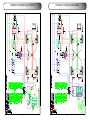
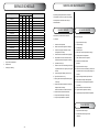
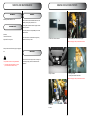
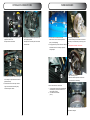
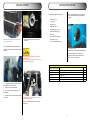
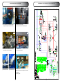
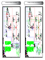
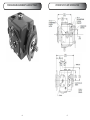
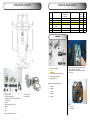
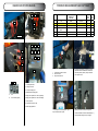
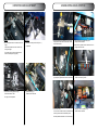
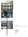
WORKSHOP
MANUAL
VITRA ECONOMY
2030/40
VER: 2.3
1
CONTENTS:
CONTENTS:
CONTENTS..............................................................................................................................................2-3
DEAR CUSTOMER.....................................................................................................................................4
VEHICLE INFORMATION...........................................................................................................................5
Safe Operation..............................................................................................................................6-9
Warning label.............................................................................................................................10-11
General Information...................................................................................................................12-14
TECHNICAL DATA....................................................................................................................................15
Identification...................................................................................................................................16
Dimensions ....................................................................................................................................17
Turning Radius...............................................................................................................................18
Climbing Ability...............................................................................................................................19
Hydraulic System: 2030 Joystick....................................................................................................20
Hydraulic System: 2030 Manuel.....................................................................................................21
Hydraulic System: 2040 Joystick....................................................................................................20
Hydraulic System: 2040 Manuel.....................................................................................................23
Electrical Schema......................................................................................................................24-28
Fuses..............................................................................................................................................29
Torque.............................................................................................................................................30
ACCESS TO MAIN COMPONENTS.........................................................................................................31
The Front Chassis..........................................................................................................................32
The rear Chassis............................................................................................................................33
Component overview.................................................................................................................34-36
SERVICE...................................................................................................................................................37
Lubricate Schedule.........................................................................................................................37
Fluids..............................................................................................................................................38
Service parts...................................................................................................................................39
Service Schedule............................................................................................................................40
Service and maintenance..........................................................................................................41-42
Engine 2030 access points........................................................................................................43-44
Engine 2040 access points........................................................................................................45-46
Hydraulics access points 2030/40.............................................................................................45-46
Parking brakes................................................................................................................................49
Cooling System..............................................................................................................................50
Air condition system .................................................................................................................51-52
Hydraulic System: 2030 Joystick....................................................................................................53
Hydraulic System: 2030 Manuel.....................................................................................................54
Hydraulic System: 2040 Joystick....................................................................................................55
Hydraulic System: 2040 Manuel.....................................................................................................56
2
TRANSMISSION SYSTEM.......................................................................................................................57
Component list ...............................................................................................................................57
Pressure Measurements and settings.......................................................................................58-64
Hydrostatic pump information....................................................................................................65-67
Adjustments or replacing the driving cable ...............................................................................68-69
Towing the machine........................................................................................................................70
STEERING SYSTEM................................................................................................................................71
Components overview....................................................................................................................72
Pressure Measurement and settings..............................................................................................73
Disassembling of steering parts.....................................................................................................74
MANOEUVRE SYSTEM.......................................................................................................................75-77
Pressure Measurements and settings............................................................................................77
Inspection and adjustment..............................................................................................................78
Manoeuvring Valve joystick............................................................................................................79
Manoeuvring valve manuel.............................................................................................................80
RETURN SYSTEM....................................................................................................................................81
PTO SYSTEM...........................................................................................................................................82
3
DEAR CUSTOMER:
Thank you very much for purchasing a VITRA.
This operator’s manual provides the information necessary for operating and maintaining your Vitra safely and properly. The contents are mainly composed of the following two items:
SAFETY INSTRUCTIONS:
Essential items which you should observe while operating the machine.
TECHNICAL INSTRUCTIONS:
Essential items which you should observe while operating the machine.
Before operating the machine for the first time, you should read this operation manual
thoroughly and carefully until you are sufficiently familiar with the operation of the
machine to do jobs safely and properly. The manual should be kept in a handy place so you
can refer to it when required. You are advised to refer to it from time to time to refresh your
understanding of the machine.
Your dealer has performed the pre-delivery service on your new machine.
He will advise you regarding the operating and maintenance instructions give in this manual,
and instruct you in the proper and varied applications of this machine. Call on him at any
time when you have a question, or need equipment related to the use of your machine.
VEHICLE INFORMATION:
The information in this publication describes the operation, maintenance and servicing of the VITRA.
Every effort has been made to provide correct and accurate information to you, the operator, as available at date of
book publication.
Your VITRA Dealer is available should items in this book or details of your machine not be understood.
This book is supplied with each machine to familiarize the operator with proper instructions needed for operation and
maintenance. Studying and complying to these instructions will insure optimum machine performance and longevity.
Properly maintained operated in the prescribed manner will provide greater dividends than one that
is neglected and/or operated in manner other than as prescribed.
The design and servicing of this machine has been kept as simple as possible to permit maintenance operations to
be carried out with tools normally available.
This book should be thoroughly read and understood prior to operation of this machine. Inexperienced operators
should study contents of this publication and receive instruction from an experienced operator when possible.
Your VITRA Dealer can also assist in areas concerning machine operation and provide details concerning safe operation. It is suggested that this booklet be kept readily accessible, preferably with the machine, for future reference if
questions or concerns arise. If the original book should become damaged, please consult your Dealer in regards to
acquiring a replacement.
Customers are strongly advised to use an official VITRA dealer in connection with any service problems and adjustments that may occur. The VITRA Dealer network is specially trained and equipped to handle all service work and to
advise customers on specific applications of the Tractor in local conditions.
Be sure to wear proper personnel protective equipment during operation.
In some of the illustrations used in this operation manual, panels or guards may have been removed to clarify
information. Never operate the tractor with these panels and guards removed.
If the removal of a shield is necessary to make a repair, it must be replaced before operation.
All information, illustrations, and specifications contained in this manual are based on the latest information
available at the time of publication. The right is reserved to make changes at any time without notice.
4
5
SAFE OPERATION:
1. HOW TO BE A SAFE OPERATOR.
1.1.
Familiarize yourself fully with machine controls by
studying the operation manual before using your
machine.
machine.
• Persons with mental disease
• Persons who cannot operate the machine properly because of fatigue, illness, or drowsiness from medication, etc.
• Young persons or children too young to legally
operate the machine.
Always be careful of your health by taking suitable rest breaks.
Wear appropriate clothing and other protective
1.3.
BEFORE STARTING THE ENGINE.
2.1.
Set up an operation plan with sufficient time
allowance. A tight plan may result in unexpected accidents when work has to be rushed.
2.2.
Inspect and service the machine periodically in accordance with the instructions given in the operation manual to maintain the machine in best condition.
2.2 A
Pay special attention to the controls, especially to the brakes and driving pedales, and safety
measures for the machine functions properly and performs normally, the chance of an accident will be reduced greatly.
If safety devices are damaged or do no work, please consult your VITRA dealer.
2.3.
Before removing a safety devices, such as a safety cover, be sure that the machine has stopped completely.
Never forget to replace the removed part after
servicing.
Never allow persons listed below to operate the
1.2.
2.
devices during operation.
Protection from poisonous dust or gases
1.4.
SAFE OPERATION:
3.6.
3,7
Never allow other persons to get on the machine or the implement except when the machine or the implement is provided with a seat or a platform for persons to sit or stand on, and only within the capacity specified. Never allow persons to get on the implement while traveling on roads.
Do not make sharp turns on a slope. It may cause
turnover of the tractor.
When climbing up a hill, shift the speed change lever to the most suitable speed. Start moving the tractor as slowly as possible.
When starting to move the tractor on an up-hill slope, be sure that the front wheels do not lift up.
When going down a hill, drive the tractor at slower
speed that used to climb up the hill.
While going down a hill, and never try to control the speed only with the brakes; use the engine brake effectively.
6. LOADING ONTO OR UNLOADING FROM A TRUCK.
Be sure to wear a protective device to protect the
respiratory system, eyes, and skin when handling
poisonous chemicals.
1.5.
When another person operates your machine, you must explain how to operate and instruct him or her to read this manual fully to avoid unexpected accident.
Before starting to move, pay attention to safety
2.4.
conditions around the machine to avoid injury to
bystanders or damage to property. Never move
abruptly.
Inspect and service the machine periodically in accordance with the instructions given in the operation manual to maintain the machine in best condition.
3. DURING OPERATION.
Pay sufficient attention to the safety conditions
6.2.
1.6.
3.1. D
uring operation, never allow other persons in the
3.2.
vicinity of the tractor, because the tractor itself or
flung pieces may cause injury.
Pay attention to safety around the tractor to avoid
injury to bystanders or damage to property. Especially when operating with other persons, use the horn to warn them. Don´t move until you see a clear intention from them.
When moving the machine toward an implement
3.5.
for the purpose if installing the implement, never
allow any one to stand in between. When installing the implement on the machine, be prepare to
move away promptly in the event of an emergency. The brakes should be applied securely during
installation.
When loading the tractor onto a truck or a trailer,
6.1.
around the tractor and have it guided by someone to assist the operation.
Never allow other persons to approach the tractor, especially in front of or behind it.
Use ramps with the same or better specifications
mentioned below. When the machine is equipped
with attachments other than those included in the
specifications mentioned below, ask your VITRA dealer for advice.
6.5.
9. INSPECTION AND MAINTENANCE.
When servicing the tractor or mounting or dis9.1.
mounting an implement, place the tractor on level,
hard ground which is sufficiently illuminated, or
unexpected accidents may occur.
9.3.
When servicing the tractor, follow the instructions listed below:
• Stop the engine.
• Apply parking brakes.
• Disengage all PTO.
• Place all gear shift levers in neutral.
• Remove the starter key.
• Lower the implement fully, if equipped.
If not, your hands or clothes may be caught or
sandwiched between.
ing makeshift tools may lead to injuries or poor
servicing, which may result in unexpected accidents during operation.
9.5.
The engine, muffler, radiator, etc. are very hot just
after operation, so wait until they cool down sufficiently to avoid burns.
Never remove the radiator cap while the engine is hot or running. Wait until the engine
cools down and then relieve the radiator pressure by releasing the radiator cap carefully. Carelessly pouring cooling water into the
heated radiator can cause serious damage to the radiator and the engine. Careless removal of the radiator cap can cause serious injury because of overheated water vapour.
9.8.
SPECIFICATIONS OF THE RAMPS.
Length
More than 4 times the height of the platform of .....
the truck Width (effective width) more than 35 cm
Capacity (one ramp) more than 1700 kg
Ramps should have anti-skid surfaces.
Always prepare for even the worst, by never al6.6.
9.9.
7
Never fit unauthorized implements or attempt unauthorized modification to the machine.
Be sure to reinstall the removed safety covers in
9.10.
lowing other persons near the tractor.
6
Drive the tractor carefully at the moment the tractor moves from the ramps onto the platform, the angle may chance abruptly.
When servicing the tractor, use proper tools. Us9.4.
turn off the truck`s engine and apply the parking
brakes to the truck or the trailer.
Otherwise, the truck could move and the tractor falls to the ground.
6.7.
place as exposed dangerous parts may cause serious injury.
SAFE OPERATION:
9.11. Avoid high-pressure fluids. Escaping fluid under pressure can penetrate the skin and cause serious injury,so keep hands and body away from pin holes and nozzles ejecting such fluids. Be sure to consult your dealer about ang the
hydraulic and fuel injection system troubles.
When checking for leaks, get sure to take the
proper precautions and proper protective clothes If any hydraulic fluid is injected accidentally into the skin, it must be removed within a few hours by a doctor familiar with this type or injury.
9.12. When servicing wheels and tires, the tractor and/
or implement must be supported on suitable blocks or stands. Not a hydraulic jack.
Do not attempt to service a tire unless you have the proper equipment and experience to perform the job.
Always remove attachments before jacking the machine.
Have the work carried out by your VITRA dealer When seating tire beads onto rims, never exceed the maximum inflation specifications specified on the tire.
Inflation beyond this maximum pressure may damaged the tire, or even the rim, with
dangerous, explosive force.
If tire have deep scratches, cuts or punctures, it
must be replaced by qualified personnel as
soon as possible.
Wear suitable protective clothing, gloves, eye/ face protection.
W
hen servicing the electric system, always be
sure to stop the engine first. Otherwise your
hands or clothes may be caught in or sandwiched
between rotating parts.
(2)
B
efore dismantling electric parts, be sure to disconnect the earth battery cable (-), or you may get
an electric shock or be injured by sparks.
(3)
L
oose electric terminals or connectors may not
only lower electrical performance but also cause
short circuit or leakage of electricity, which may
lead to a fire.
Promptly repair or replace damaged wiring.
R emove chaff of dust from the battery, wiring,
muffler, or engine. Otherwise it could result a fire.
12. STORAGE.
12.1. Never cover a hot machine just after operation with a tarpaulin or the like, or the heated engine and related parts may cause a fire.
12.2. Before storing the tractor for a long period of time,
10.2. TO HANDLE THE BATTERY.
(1)
When working around the battery, avoid smoking.
The battery generates explosive hydrogen and oxygen gases when being charged.
Keep the battery away from sparks or open flames.
(2)
The battery should be inspected before starting
(3)
When replacing or inspecting the battery, always
(4)
When disconnecting the battery cables, disconnect the earth cable (-) first.
When connecting the battery cables, connect the positive cable (+) first.
Disconnecting or connecting in wrong order may lead to a short circuit or sparks.
the engine. Be careful not to touch the electrolyte
when removing the vent plugs. If the battery electrolyte makes contact with the skin or clothing,
wash it off immediately with water. Consult a doctor.
disconnect the battery cables to prevent them, in
case they are gnawed by a animal, from causing a short circuit, which may lead to a fire. When disconnecting the cables, disconnect the
negative (-) cable first.
Safe storage of dangerous objects
• When storing dangerous implements, take appropriate safety measures to prevent accidents by covering with tarpaulin.
• Store fuel in a safe place with caution signs such as “PREVENT FIRE” or “INFLAMMABLE”.
• All inflammable must also be stored in a safe, fire resistant location.
stop the engine and turn the main switch off, or
electrical parts may be damaged or unexpected
accident may occur.
10.3. TO HANDLE BOOSTER CABLES.
10. MAINTENANCE OF THE ELECTRIC SYSTEM.
(1)
(4)
SAFE OPERATION:
When using booster cables, pay attention to the following items for safe operation:
(1) Before connecting cables, remove the vent plugs. ( If any. )
This will lower the force in case of explosion.
(2) Before connecting cables, be sure to stop the engine.
Otherwise unexpected accidents may occur.
(3) Use booster cables with sufficient electrical capacity.
A cable of inadequate capacity will cause generation of heat, which may lead to a fire.
8
9
WARNING LABELS:
ADV1510
WARNING LABELS:
ADV1570
WARNING: ROTATING PARTS:
(Code No. ADV1510)
WARNING: RISK OF EXPLOSION
(Code No. ADV1570)
ADV1590
ADV1530
IMPORTANT: READ USER MANUAL
(Code No. ADV1530)
WARNING: ROTATING PARTS:
(Code No. ADV1510)
ADV1610
ADV1550
DANGER: RISK OF EXPLOSION AND BURNS
(Code No. ADV1610)
WARNING: DISCONNECT BATTERY
(Code No. ADV1550)
ADV1630
ADV1690
WARNING: RISK OF OVERTURNING
(Code No. ADV1630)
Danger:
(Code No. ADV1690)
ADV1650
ADV1710
Danger:
(Code No. ADV1710)
WARNING: HIGH PRESSURE STEAM AND HOT
WATER
(Code No. ADV1650)
ADV1670
FILLING HYDRAULIC OIL:
(Code No. ADV1670)
ADV1730
(Code No. ADV1730)
10
11
GENERAL INFORMATION:
(1) BEFORE OPERATION
(c) When installing a bearing, which appears the
same on both sides, install it so that the face,
which has the identification number faces in a
direction for easy visual identification. All the
bearings, which are to be installed in
transmission case should be placed so that their
identification number faces outward.
(a) Always be safety/conscious in selecting clothes
to wear and suitable tools to use.
(b) Before disassembly, be sure that you familiarize
yourself with the assembled condition for
subsequent reference in reassembly.
(d) If a shaft or a hole where a bearing is to be
installed has a stopper, the bearing should be
pushed in completely until it is seated against
the stopper.
(c) Keep parts and tools in proper order during
operations.
(d) When servicing electrically live parts, be sure to
disconnect the negative battery terminal.
(e) Installed bearings should turn smoothly.
(2) Oil seals.
(e) To prevent oil or water leaks, use the liquid
gasket as required.
GENERAL INFORMATION:
(4) Snap-rings
(c) The roll pins installed in a transmission or other
parts where much force is applied should be
retained with wire.
(a) Snap-ring installers should be designed to avoid permanent deformation the snap-rings.
(6) Cotter pins
(b) Installed snap-rings should be seated securely in
the groove.
(a) When installed, cotter pins should be bent
securely at the ends as shown in the figure.
(c) Be careful not to overload the snap-ring to the
extent that it is permanently deformed.
(d) How to install the snap-ring:
When installing a snap-ring, install it as shown in
the figure with its round edge side turned toward
the part to be retained. This round edge is
formed when the snap-ring is pressed out.
(a) Oil seal installer should be designed to avoid
deformation the oil seals.
(f) When reassembling disassembled parts, discard
used gaskets, O-rings, or oil seals and install
new ones.
(7) Bolts and nuts
(a) Special bolts are installed at several locations, so
be sure not to interchange them other bolts.
(b) During installation, be careful not to damage the
lips, and assure that it is pushed in parallel to the
shaft or hole.
(g) When lifting up only the front or rear part of the
tractor, be sure to wedge the grounded wheels.
(b) Bolts and nuts should be tightened to their
specified torque with a torque wrench.
(c) When oil seals are installed, there should be
neither turnover of the lips nor dislocation of the
springs.
(h) When the tractor is jacked up, be sure to support
the entire tractor with something like a stand.
Lifting it up with a jack only is a dangerously
unstable procedure.
(d) When a multi-lip seal is installed, the grooves
between lips should be filled with grease, not
adhesive.
(i) When replacing parts, use authorized, genuine
VITRA parts only. VITRA assumes no
responsibility for accidents, operating problems
or damage caused by the use of imitation parts.
Also, the use of unauthorized parts will result in
poor machine performance.
(e) Use a lithium-based grease.
(f) There should be no oil or water leaks through the
installed soil seals.
(3) O-rings
(2) PRECAUTIONS TO BE FOLLOWED WHEN
INSTALLING COMMON PARTS.
(1) Roller or ball bearings.
(a) When a bearing is fitted in by the outer ring, use
an installer, which is specially designed to push
only the outer ring and vice versa.
(b) The installer must be designed to install the
bearing on the shaft in a parallel position.
(c) When locking the bolts or nuts with wire or a lock
washer, be sure to wind the wire paying sufficient
attention to its winding direction and bend the
lock washer for secure locking.
(d) When locking bolts and nuts with an adhesive,
apply the adhesive on the thread and tighten
securely.
(5) Spring (roll) pins.
(a) Spring pins should be driven in properly and
tightly.
(e) Apply an adhesive (THREE BOND TB 1104) to
parts through which there is any possibility of oil
leaks, such as stud bolts and tapped-through
parts.
(b) Spring pins should be installed so that their
seams should face the direction from which the
load is applied.
(a) O-rings should be coated with grease before
installing.
(f) Each lock nut must be tightened securely.
(b) Installed O-rings should have no slack or twist.
(g) When tightening bolts and nuts, refer to the
tightening torque table.
(c) Installed O-rings should maintain proper air
tightness.
(8) Grease fitting.
(a) After installation, each grease fitting should be
filled with grease.
12
13
GENERAL INFORMATION:
TECHNICAL DATA:
Type:
(b) When installing grease fittings of types B and C,
be sure to turn the fitting tips in a direction that
will provide easy access for a grease gun.
Dim:
Engine.
(9) Other precautions.
2040 Quantity:
Caterpillar C1.6
Performance.
kw/HK
18 kw / 29 HK 3600 r/min.
25 kw / 36 HK 3000 r/min.
Displacement.
cm3
1131
1598
3400
3000
N.m
70 / 2300
94 / 1800
23:1
23.1
28
28
10-40 CD/CE
10-40 CD/CE
High Idle Speed.
Max Torque.
(a) Be sure not to damage any finished surfaces or
parts.
2030 Quantity:
Caterpillar C1.1
Compression Ratio.
(b) Always refrain from forcing installation.
Fuel Tank.
L
Engine Crankcase with Filter.
SAE
Quantity.
L
Diesel fuel quality.
(c) Each lever knob should be installed coated with
an adhesive (SUPER THREE CEMENT TB1702)
Cooling system.
(d) Each contact surface should be coated with an
adhesive (THREE BOND TB1215) and tightened
evenly with bolts. Adhesive coated surfaces
should be installed within 30 minutes after
application of the adhesive.
The contact surfaces should be flawless and free
from foreign matter, and especially from grease
before application of the adhesive.
5.6
ASTM D975
ASTM D975
Autosupra G12
Autosupra G12
6
6.5
Quantity.
L
Valve Clearance (Cold).
mm
0,2
0.2
Charging. (Option)
Amp.
40 (60)
40 (60)
Battery.
Amp.
450
450
Transmission.
Hydrostatic Transmission.
Hydrostatic Transmission.
Wheel Motor.
4
4
0-24
0-28
Gear Pump.
Gear Pump.
Speed.
Km:
Working hydraulics.
(e) Precautions for applying adhesives
The surface or the thread where an adhesive is
to be applied should be completely free of chips
and oil.
The surface or the thread where an adhesive is
to be applied should be completely free of
oiliness.
* 4.4
Max Capacity.
l/min.
Max pressure.
Bar.
Output.
l/min.
Hydraulic tank.
L
Oil type.
Manoeuvre Hydraulics.
50
50
200 Bar.
200 Bar.
43L ved 180 Bar.
44L ved 180 Bar.
25
25
OK hydraulik HVI 46
OK hydraulik HVI 46
Gear Pump.
Gear Pump.
14 l/min v.140 Bar
14l/min v.140 Bar
Hydraulic outlet. Rear
1 double with lock + 1 Small PTO.
1 double with lock + 1 Small PTO.
Hydraulic outlet. Front
1 double with lock + 1 Small PTO.
1 double with lock + 1 Small PTO.
Capacity.
Type:
Dim:
Weights and measures.
Quantity:
Quantity:
Specifications are subject to change
without notice
Specifications are subject to change without
notice
Length.
mm.
2745
2745
Wide std.
mm.
1031
1031
With Wide Wheels.
mm.
1150
1150
Height.
mm.
1993
1993
Clearance.
mm.
129
129
Turning Radius.
mm.
907
907
Weight.
Kg.
1050
1100
Total weight.
Kg.
1750
1750
23/10,5-12 6 lag
23/10,5-12 6 lag
Bar.
1,5
1,5
Engine cover.
Ral
5010 Blue
5010 Blue
Cabin.
Ral
5010 Blue
5010 Blue
Chassis color.
Ral
7021 Dark Gray
7021 Dark Gray
Rim color.
Ral
9001 White
9001 White
Tire sizes.
Standard.
Tire pressure. unloaded.
Color.
14
15
IDENTIFICATION:
DIMENSIONS:
Type plate is placed under the roof in the cabin.
Front frame No. Placed in the top plate right side pivot point.
Front frame No. Placed in the top plate right side pivot point.
16
17
TURNING RADIUS:
CLIMBING ABILITY:
18
19
HYDRAULIC SYSTEM: 2030 JOYSTICK
20
HYDRAULIC SYSTEM: 2030 MANUEL
21
HYDRAULIC SYSTEM: 2040 JOYSTICK
22
HYDRAULIC SYSTEM: 2040 MANUEL
23
ELECTRICAL SCHEME:
ELECTRICAL SCHEME:
24
25
ELECTRICAL SCHEME:
ELECTRICAL SCHEME:
26
27
FUSES:
ELECTRICAL SCHEME:
(1)
15 Amp. Instrument lights.
(2)
10 Amp. Kl. 15 Hand brake and fuel - A / C.
(3)
15 Amp. Switch for 7 pole Trailer Connector.
(4)
10 Amp. PTO. A/C - Joystick kl 15.
(5)
15 Amp. Driving seat, and cabin roof.
(6)
15 Amp. Stop Solenoid and Blowers.
(7)
10 Amp. Wiper + sprinklers.
Fuse box ( upper panel )
1. Working light.
2. Hazard + Aux. (8) 5 Amp. Engine preheating.
(9)
20 Amp. Brake lights and Alternator Kl.15
(10)
5 Amp. Reverse contact. ( Optional )
(11)
15 Amp. Rotating beacon.
(12)
15 Amp. High beam.
(13) 15 Amp. Low beam.
(14)
5 Amp. Position light.
(15)
5 Amp. Position light.
(16)
7,5 Amp. Horn. Main fuses.
1. Upper panel.
2. Steering column.
The panel are placed under the fuel tank.
Main fuses.
1. Upper panel.
2. Steering column.
3. A/C and joystick.
The panel are placed under the fuel tank.
28
29
ACCESS TO MAIN COMPONENTS:
TORQUE:
Dim:
M5
M6
M8
M10
M12
M14
M16
M18
M20
8.8 bolts und Nuts
10.9 bolts und Nuts
N-m (kgf-cm)
N-m (kgf-cm)
2.9 - 3.9
4.9 - 5.9
(0,30 - 0,40)
(0,50 - 0,60)
5.9 - 7.8
8.8 - 10.8
(0,60 - 0,80)
(0,90 - 1,10)
12.8 - 17.7
19.6 - 26.5
(1,30 - 1,80)
(2,00 - 2,70)
19.6 - 29.4
44 - 54
(2,00 - 3,00)
(4,50 - 5,50)
49 - 59
74 - 88
(5,00 - 6,00)
(7,50 - 9,00)
69 - 78
98 - 118
(7,00 - 8,00)
(10,00 - 12,00)
98 - 118
118 - 137
(10,00 - 12,00)
(12,00 - 14,00)
118 - 137
157 - 177
(12,00 - 14,00)
(16,00 - 18,00)
147 - 167
186 - 206
(15,00 - 17,00)
(19,00 - 21,00)
Remark:
Location:
Loctide
Dim:
N-m (kgf-cm)
Nut center bolt.
x
M35
300 (30)
M25
200 (20)
Centre Nut hub.
+ to nearest hole
Bolts in the anchor plate.
x
5/16x20
35 (3,5)
Bolt brake arm.
x
M8
40 (4)
1. The front lift must be lowered before tilting the cabin.
(Danger of damaged of the lower Windshield)
1. Loosen the front cabin suspension before tilting the cabin.
1. The safety brackets must be used when tilting
1. Safety bolt.
the cabin.
2. Hole for safety bolt.
3. Rear cabin mounts.
Bolts in the flywheel.
x
Hydraulic Motor on diesel.
5/16x20
55 (5,5)
M10
60 (6)
Bolts on HST.
x
M12
60 (6)
Bolts on Tandem Pump.
x
3/8 unc
50 (5,5)
M14
120 (12)
Wheel nuts.
30
Danger.
Before working on the cabin, the safety bolt must be
inserted.
31
FRONT CHASSIS:
1. It is highly recommended that you clean out all dirt
under the cabin you start to work on the Machine.
To prevent dirt into the Hydraulic System during Maintenance or repair. 1. It is important to ensure that the two rear suspen
sion returns properly into place.
1. Prior to lowering the Cabin, make sure
that cables and wiring are in their correct places.
1. The safety brackets must be used when tilting
the cabin.
REAR CHASSIS:
1. Engine access by removing the engine cover.
Unlock 1 to 3 before removing the covers.
1. Rear lock of the fuel tank.
Lever pos. 1 is turned down, then the Tank can be turned out.
1. The fuel tank is hinged and can be turned out to ensure better access to the Engine Compartment.
1. Turning the fuel Tank gives access to. Electrical Components and Service Parts:
V-Belt, Starter, Alternator, Water Pump, Battery,
Exhaust, main Fuses and Air Filters.
2. Hole for safety bolt.
3. Rear cabin mounts.
REMEMBER TO TIGHTEN THE SUSPENSION.
IT IS VERY DANGEROUS TO DRIVE IN THE MACHINE IF THE REAR SUSPENSION IS UNSECURED.
Danger.
Before working on the cabin, the safety bolt must be
inserted.
32
33
COMPONENT OVERVIEW:
17
18
34
COMPONENT OVERVIEW:
Nr.
1
2
3
4
5
6
7
8
9
10
11
12
13
14
15
16
17
18
Description.
Hydraulic tank.
Fuel tank.
Hydraulic return filter.
Fuel filler cap.
Steering cylinder.
Lift cylinder.
Right rear wheel motor.
Left rear wheel motor.
Right front wheel motor.
Left front wheel motor.
PTO valve.
Manoeuvre valve/ joystick block.
Radiator filler.
Battery.
Main fuses.
Dipstick.
Small PTO valve.
Weight transfer valve.
35
COMPONENT OVERVIEW:
Nr.
1
2
3
4
5
6
7
8
9
10
11
12
13
Description.
Throttle.
Joystick/ Manoeuvre levers.
Reverse pedal.
Forward pedal.
Cabin temp adjustment.
Air nozzles.
Fuse panel.
Steering column.
Fuse panel.
Seat Height adjustment.
Seat Backrest adjustment.
Electronic for aircon and manoeuvre funktion.
Cabin heater.
LUBRICATION SCHEDULE:
Lubricate Nipple:
Interval:
1
Steering Cylinder Rear.
Week.
2
Steering Cylinder Front.
Week.
3
Liftcylinder Rear.
Week.
4
Liftcyllinder Front.
Week.
5
Center Linkage.
Daily.
6
Door hinges.
Monthly
Use grease type: Molytex EP2
36
37
FLUIDS:
Fluid types:
SERVICE PARTS:
Quantity:
Quantity:
2030
2040
1
Motor oil Texaco Ursa Premium TD 10W-40
4,4 L
5,0 L
2
Coolant Havoline XLC
6,0 L
6,0 L
3
Diesel ASTM D975
28 L
28 L
4
Hydraulic oil Texaco HDZ 46
25 L
25 l
4A
Hydraulic oil Texaco Hydral 46
25 L
25 L
5
Wind screen washer fluid
1L
1L
7
KEY
1
1a
2
2a
3
4
4a
5
6
7
8
Be sure to place the machine on a flat, clean surfaces before control of oil levels or change of Oil.
38
PART CODE
MOT9105
MOT9103
HYD1916
HYD1927
HYD1912
MOTC1520
MOTC1525
MOTC1530
DIV2072
MOTC2015
MOTC2020
DESCRIPTION
Air filter element 2030
Air filter element 2040
Return filter element 2030
Return filter element 2040
Filter element for filler cab 2030/40
Engine oil filter 2030
Engine oil filter 2040
Fuel filter 2030/40
Cabin filter 2030/40
V-belt 2030/40
V-belt A/C 2030/40
Option.
Cabin pollen filter DIV2070
39
DIV.
Option
SERVICE SCHEDULE:
Subjects.
Service interval:
Daily.
Year.
Motor oil.
●
●
Motor oil Filter.
●
●
●
●
○
Air filter.
○
Coolant.
○
Battery.
○
Hydraulic oil.
○
these inspections must been carried out by a
authorized dealer.
□
●
●
Medium pressure filter.
●
●
Only on the 2045/2060
●
Dieselfilter.
●
○
Wheel Bolts.
○
Lubricating nipples.
○
Brakes / Handbrakes.
○
Cooler.
○□
V-belt.
○
50 HOUR SERVICE:
500 HOUR SERVICE:
●
Hydraulic return filter.
Tire pressure.
All servicing Shall be performed at a Authorized
VITRA Dealer. To ensure one year factory warranty
3000 HOURS OR 5 YEARS
Breather filter.
○
Comments.
500 h
Motor oil stand.
50 h
SERVICE AND MAINTENANCE:
Moly Grease
□
□
●
Daily check and adjustment.
● Replacement.
□ Cleaning and washing.
(Or once every year.)
run 50 hours.
1. Engine oil and filter change.
●
○
□
Performed only 1 time when the tractor has 1. Coolant must be inspected.
2. Fuel filter change.
2. Water hoses must be inspected for damage.
3. Air filter replace.
3. V-belt for water pump / Alternator checked
4. Coolant inspect.
and tightened if necessary.
5. Water hoses must be inspected for damage.
4. Exhaust div. Nuts and bolts must be tightened.
6. V-Belt inspection and adjustment.
5. All Hydraulic hoses and connections must be
7. Valve clearance check and adjusted.
Inspected for leaks and retighten if necessary.
8. Exhaust nuts and bolts must be
6. Hydraulic filter change.
tightened.
7. Check the nuts in the centre linkage and be sure
9. Hydraulic oil and filter change.
to hydraulic hoses run the right way through the
10. Check the nuts in the centre linkage and be sure
machine.
to hydraulic hoses run the right Way through the
8. Inspect and tighten all bolts, joints and nuts.
machine.
9. Tighten Wheel nuts to 12 Kg.
11. Inspect and tighten all bolts, joints and nuts.
10. Driving cable must be inspected and adjusted
12. Hand brake and adjust cable adjustment.
if necessary.
13. Driving cable must be inspected and adjusted
11. Check hand brake and cables for fractures and
if necessary.
adjusted cable if necessary.
14. Check all electric functions/connections.
Check drum brakes and cables for fractures. 15. Inspect cabin filter, replace if necessary.
12. Check all electric functions/connections. 16. Inspect/change the wiper blades and Sprinkler.
13. Inspect cabin filter replace if necessary.
14. Inspect the wiper blades and sprinkler.
YEAR SERVICE:
1. Hydraulic oil and filter change.
2. Wheel brakes must be inspected and
cleaned up.
40
41
SERVICE AND MAINTENANCE:
ENGINE OIL.
ENGINE 2030 ACCESS POINTS:
COOLANT.
Mobil Super 2000 10W-40 SL / CF.
OK Excellent coolant and distilled water in the ratio
50/50% providing frost protection to -37 *.
Cooling water should be checked for proper mixture
HYDRAULIC OIL.
before frost sets in.
It is entirely the owner’s responsibility to ensure the
above matters.
Standard:
Texaco HDZ 46 ca. 25 l.
The coolant fluid is recommended changed every
Option: Bio Texaco hydraul
3000 hours or every 5 Years.
1. Rear cover under the machine.
1. The fuel filter (on the left side of the engine.
Before changing the filter you must clean around it.
Always check the level after changing/ or topping the
Oil.
AIR FILTER.
The air filter must be changed when it no longer can
The Hydraulic oil must be change immediate if.
be cleaned properly, however, At least 500 hours
1. The oil has been overheated 80^ or higher.
(The oil becomes a brownish colour) operation.
1. Engine oil drain.
1. The engine oil filter.
Access point behind left rear wheel.
Before changing the filter you must clean around it.
1. Generator.
2. V-belt.
42
43
ENGINE 2030:
ENGINE 2030/40 ACCESS POINTS:
Breather position and assembly.
1. The air filter.
1. Rear cover under the machine.
1. The fuel filter (on the left side of the engine)
2. The oil filler cap. Before changing the filter you must clean around it.
Before changing the filter you must clean around it.
1. The dipstick.
1. Engine oil drain.
1. The engine oil filter.
Access point behind left rear wheel.
Before changing the filter you must clean around it.
1. Filling the engine with oil.
Left hand side of the engine.
1. Generator.
2. V-belt.
44
45
ENGINE 2040:
HYDRAULICS ACCESS POINTS:
Breather position and assembly.
1. The air filter.
2. The oil filler cap. Before changing the filter you must clean around it.
1. Drain for Hydraulic Oil.
1. Tank Venting Filter.
Placed below the hydraulic tank. 2. Filter Breeder.
Remember to clean around the tank and filter before
Opening.
1. The dipstick.
1. The return oil filter.
2. The oil filler cap and filtered breather.
Remember to clean around the tank and filter
1. Hydraulic oil thermometer placed on the front of the
before working on them.
hydraulic tank. 1. Filling the engine with oil.
Left hand side of the engine.
46
47
HYDRAULICS CONNECTIONS:
PARKING BRAKES:
1. All Hydraulic Couplings on the machine must be
1. The Hydraulic Hoses must be inspected visually
1. Too much slack on the cable reduces the Disassembling of the Drum Brake.
inspected at each service.
and couplings tightened.
brake therefore must the cable be adjusted at Example: Left rear wheel motor.
Example: Picture of the front part of the chassis
point 1 (not self-adjusting)
under the cabin.
2. Hanging brakes may be due to Rust in the Cable or 1. Remove the safety Pin and loosen the Center Nut. (Let it stay on so the Drum not fly of when you pull it
of.)
the Brakes. Grease or if necessary replace the
2. Nut tightened to 200 Nm + nearest hole.
damaged parts.
1. Min:. Brake lining 1.5 mm
1. The Hydraulic Hoses on the machine must inspect
2. Make sure that all Components are clean and ed for damage. It is important that the hoses are
Lubricated before re assembling.
positioned correctly.
2. The Belt mounted in the centre pivot, must be
Picture of the socket for the hand brake.
tight net to ensure all hoses moving freely,
1. To ensure proper function of the hand brake light,
the switch (Pos. 1) has a lever which can be
manually bent to adjust.
2. The cable of the hand brake.
(Pos. 2) without touching the chassis. Picture of brake cable attachment at the drum brake.
Tjek cabel for damages.
48
49
COOLING SYSTEM:
AIRCONDITION SYSTEM:
The a/c system consists of following parts.
Radiator has to be cleaned daily, or whenever it is clotted by grass or leaves.
1. Proper coolant level must just cover the slats in the radiator.
•
Compressor. (Fig. 2)
•
V - belt. (Fig. 2)
•
Capacitor. (Fig. 1)
•
Pressure filter. (Fig. 3)
•
Low pressure switch. (Fig. 3)
•
Pressure Transmitter. (Fig. 4)
•
Relay. (Fig. 7)
•
On / off switch. (Not illustrated)
•
Fuse at battery. (Fig. 6)
•
Fuse. at the steering collum. (Fig. 5)
The a/c system performs best if you recirculate the
air. Fog on the windows are also removed best by
recycling.
The machine is fitted with a quick release prefilter.
1.
To ensure enough cooling this filter must be kept clean
at all times.
Nozzle for recycle.
Under optimum conditions the a/c system will be able
to lower the temperature in the cabin app. 7 gr. relative to the outside temperature. Radiation from the
Should be exercised great caution when working on
a cooling system.
The cooling system is pressurized with very hot water
which may boil at pressure drop.
sun may influence on the performance.
The a/c system will not work in the following situations.
Below 0-3 degrees Celsius.
Pressure loss.
Can be tested by short-circuiting the pressure switch.
Defect V-belt.
Change the V-belt.
Blow fuse.
Change fuses.
Defect relay.
Change relay.
Frozen evaporator.
Adjust the pressure transmitter.
1. High pressure cleaning of the radiator must be done cautiously to avoid any damage.
2.
Soak up the cooler with water/soap.
3.
Afte ½ hour, clean up the cooler with not to
much pressure.
3.
Important: Clean up vertical to prevent damage
1. The radiator has to be cleaned daily, or whenever it
is clotted by grass or leaves.
of cooler fins.
Picture of the cooling system seen from the engine
compartment.
50
51
Fig. 3
Fig. 2
Fig. 6
Fig. 7
Fig. 4
AIRCONDITION SYSTEM:
HYDRAULIC SYSTEM: 2030 JOYSTICK
Fig. 5
Fig. 1
1. The condenser must be cleaned regally with
1. Fuse for A/C. No.4 from right.
compressed air. (Must be done with caution.)
Placed in the fuse box on the steering collum.
Fig. 2
Fig. 6
1. V-belt is tightened by loosening the bolt pos. 1
1. Fuse for A/C. No. 3
and then tilting out of the compressor.
Placed under the fuel tank.
Fig. 3
Low press switch
placed under the cabin.
Fig. 4
Fig. 7
Pressure switch
placed under the cabin.
Relæ for a/c. No. 3
Placed in the technic box in the right side of the cabin.
1. Fuse for a/c.
2. Fuse for joystick.
52
53
HYDRAULIC SYSTEM: 2030 MANUEL
HYDRAULIC SYSTEM: 2040 JOYSTICK
54
55
HYDRAULIC SYSTEM: 2040 MANUEL
TRANSMISSION SYSTEM:
1.
2.
3.
4.
5.
6.
56
57
Hydrostat. (Not illustrated)
Wheel Motor left front.
Wheel Motor right front.
Wheel Motor left rear.
Wheel Motor right rear.
Bypass valve
for towing.
PRESSURE MEASUREMENTS AND SETTINGS:
Nr.
PRESSURE MEASUREMENTS AND SETTINGS:
COMPONENT.
MEASURING
CONNECTOR
LOCATION.
ADJUST ITEM.
PRESSURE.
2040
PRESSURE.
2030
1
PTO.
FRONT
PTO BLOK
200
200
2
MANOEUVRING.
FRONT
UNDER THE WAGON
160
160
3
ORBITROL.
ORBITROL
ORBITROL P-PORT
150
150
4
OPERATING PRESSURE.
HYDROSTATIC PUMP
HYDROSTATIC PUMP
300
250
5
BUSTER PRESSURE.
HYDROSTATIC PUMP
HYDROSTATIC PUMP
12
12
6
RETURN PRESSURE.
FRONT
NON ADJUSTABLE.
0,5-1,5
ADAPTERS.
Booster pressure.
Booster pressure.
1. Booster pressure valve: Not adjustable.
1. Measuring nozzle No. 2 to be mounted between
0,5-1,5
Position on the top of the Hydrostatic pump.
Hydrostatic pump and the hose from orbitrol.
Measuring adaptors.
2.
Manoeuvring functions.
3.Orbitrol.
4.
Driving pressure from the Hydrostate.
5.
Booster Pressure Hydrostate.
6.
Drain front and rear.
Measuring connectors have Parts. No.
2.VÆ8220
3.VÆ8200
4.VÆ8210
5.VÆ8205
6.VÆ8215
58
59
Pressure must be 12 Bar. at engine rpm.
PRESSURE MEASUREMENTS AND SETTINGS:
PRESSURE MEASUREMENTS AND SETTINGS:
LPV pumps are equipped with a combination high pressure relief and charge check valve. The high-pressure
relief function is a dissipative (with heat generation)
pressure control valve for the purpose of limiting excessive system pressures. The charge check function acts
to replenish the low-pressure side of the working loop
with charge oil.
Each side of the transmission loop has a dedicated
HPRV valve that is non-adjustable with a factory set
pressure. When system pressure exceeds the factory
setting of the valve, oil is passed from the high pressure
system loop, into the charge gallery, and into the low
pressure system loop via the charge check. The high
pressure relief valve used on LPV is designed to remove
pressure spikes for short periods of time. Operating over
the high pressure relief valve for extended periods may
damage the pump.
Driving pressure:
Measuring Nozzle No. 3 To be mounted between the 1. Bolt (Pos. 1) for neutral adjustment.
Hydrostatic pump.
Positioned on the right hand side of the Hydrostatic
pump.
Pressure forward and reverse.
2030 = 250 Bar.
2040 = 300 Bar.
Port A forward
pressure.
Port B reverse
pressure.
1. Relief valve reverse is not adjustable.
1. Relief Valve forward is not adjustable.
Positioned on the left hand side of the Hydrostatic
pump.
Positioned on the right hand side of the Hydrostatic
pump.
60
61
The LPV contains a dedicated bypass valve. the bypass
function is activated when the bypass valve is mechanically backed out 3 full turns (maximum).
The bypass function allows a machine or load to be
moved without rotating the pump shaft or prime mover.
PRESSURE MEASUREMENTS AND SETTINGS:
PRESSURE MEASUREMENTS AND SETTINGS:
Excessive speed or extended movement will damage
the pump and motor(s)
Avoid excessive speeds and extended load/vehicle
movement. Do not move the load or vehicle more than
20 % of maximum speed or for longer than 3 minutes.
When the bypass function is no longer needed, reseat
the bypass valve to the normal operating position.
An internal charge relief valve regulates CPRV valve
charge pressure. The charge pump supplies pressure to
maintain a minimum pressure in the low side of the
transmission loop.
Minimum charge pressure is the lowest pressure allowed to maintain a safe working condition in the low
side of the loop.
Maximum charge pressure is the highest charge pressure allowed which provides normal component life.
Elevated charge pressure can be used as a secondary
means to reduce the swash plate response time. The
charge pressure setting listed in the order code is the
set pressure of the charge relief valve with the pump in
neutral, operating with 5 gpm of charge flow. The charge
pressure setting is referenced to case pressure.
Charge pressure is the differential pressure above case
pressure.
LPV is designed for a maximum charge flow of 57 L/min
[15 US gal/min].
62
LPV pumps incorporate an integral loop flushing valve,
which removes heat and contaminants from the main
loop.
63
PRESSURE MEASUREMENTS AND SETTINGS:
HYDROSTATIC PUMP INFORMATION:
64
65
HYDROSTATIC PUMP INFORMATION:
HYDROSTATIC PUMP INFORMATION:
66
67
ADJUSTMENTS OR REPLACING THE DRIVING CABLE:
ADJUSTMENTS OR REPLACING THE DRIVING CABLE:
The driving cable of a Vitra tool carrier has a very central function. The cable is vital for the daily movement of
the Machinery, particularly for acceleration and deceleration. It is fore that matter importance that this cable
works perfectly.
The errors that can occur around the driving cable are as follows.
The cable is removed from its original alignment,
which can result in the Cable moving slowly being
damaged or worn.
If the Cable has been injured, replace it, and then
adjust it.
The cable can get out of adjustment, which can result The solution is to find the correct neural position and
in wrong Pedal position, incorrect neutral position, etc. then adjust the pedal and cable.
This is because usually, one of the previous mention
reasons, but it may also be due to a pedal that has
come loose on the Axle.
Sluggish pedals can also be caused by a worn or
broken rocker arm on the Hydrostatic pump
Replace the rocker arm.
If the pedal moves freely but will not return to the
neutral position, this is due to a broken gas spring on
the Hydrostatic arm.
Replace the gas spring.
Be careful not to get undercoating sprayed on the Cable ends. It will penetrate the cable an prevent the
cable from moving freely.
1. Washers, Nuts and Rubber Caps are fitted.
FIG. 1
2. Mount the Cable on the adjusting Bracket, then the Lever on the Hydrostate is pushed manually to max rear position toward the engine, The Cable must be secured at this position.
1.
Tilt the cabin and clean the machine.
2.
Remove the lower bolt in the front window. (Pos: 1) IMPORTANT
3.
Remove the floor mat and remove the bolt and nut in pedal housing. (Pos: 2)
4. Disconnect the driving cable on Hydrostatic pump. (Pos: 3)
5.
Remove all joints nuts, washers and rubber cap, then pull the cable out through the cabin incl. ... Pedal housing.
6.
Remove the cable from the pedal housing. (Pos: 4)
7.
Then extracted Cable is shown at (Pos.1)
It is adjusted by (Pos, 2) until the pedal is as shown
with cable fully extended.
Attach the new cable on the pedal housing, Fig.1
11. Washers, nuts and Rubber Caps are refitted.
12.
Mount the cable on the adjusting bracket, push the lever on the hydrostate are pushed manually to max rear position toward the engine, The cable must be secured at this position.
1. The Pedal Height is adjusted after the cable is
installed.
2. The forward Pedal should be app. 13 cm. above
the floor.
The rearward Pedal must be app. 7 cm. above
Floor.
3. Losen nut at pos.2 fore pedal height adjustment.
68
The Cable must be mounted in Pedal Housing first,
then adjusted as shown above.
The Pedals are Positioned as shown in picture.
Before the new cable is installed, check that the new cable has the correct length.
8. Check the condition of joints and bearing before reassembling.
9.
Adjusting the Driving Cable.
69
TOWING THE MACHINE:
In case of having to tow the machine the instructions
below must be followed carefully.
The hydrostatic pump contains a dedicated bypass
valve. the bypass function is activated when the bypass
valve is mechanically backed out 3 full turns (maximum).
The bypass function allows a machine or load to be
moved without rotating the pump shaft or prime mover.
STEERING SYSTEM:
You will need Molybdenum grease to lubricate slow moving parts under a high pressure.
The properties of this grease is great adhesion ability and great strength.
1. Hydrostatic pump bypass Screw. (Pos. 1)
Positioned on the left hand side of the Hydrostatic
pump.
2.
Transportation speed must not exceed 3 km/h.
3. Towing is only fore small distance f.eks. pull up
on a trailer.
70
Steering Cylinder front bracket.
Steering Cylinder rear bracket.
Placed on the right hand side of the machine under
the cabin.
Placed on the right hand side of the machine under
the pivot point on the rear part of the chassis.
Top centre linkage. Option: Maintain free.
Bottom centre linkage.
71
COMPONENTS OVERVIEW:
PRESSURE MEASUREMENT:
Nr.
COMPONENT.
MEASURING
CONNECTOR
LOCATION.
ADJUST ITEM.
PRESSURE.
2040
PRESSURE.
2030
1
PTO.
FRONT
PTO BLOK
200
200
2
MANOEUVRING.
FRONT
UNDER THE WAGON
160
160
3
ORBITROL.
ORBITROL
ORBITROL P-PORT
150
150
4
OPERATING PRESSURE.
HYDROSTATIC PUMP
HYDROSTATIC PUMP
300
250
5
BUSTER PRESSURE.
HYDROSTATIC PUMP
HYDROSTATIC PUMP
12
12
6
RETURN PRESSURE.
FRONT
NON ADJUSTABLE.
0,5-1,5
0,5-1,5
ADAPTERS.
Measuring adaptors.
2.
Manoeuvring functions.
3.
Orbitrol.
4.
Driving pressure from the Hydrostate.
5.
Booster Pressure Hydrostate.
6.
Drain front and rear.
1. Measuring nozzle No. 1 is mounted on the input from the pump. The measured pressure must be
150 bar. Placed under the cabin.
Before testing tilt the cabin following instructions
on page 29.
Measuring connectors have Parts. No.
2.VÆ8220
3.VÆ8200
4.VÆ8210
1. Steering cylinder.
2. Forward steering bracket.
3. Hydraulic pump. Not illu. Mounted left side
on the engine.
4. Orbitrol.
5. Bearing housing for welding.
6. Bearing.
7. Pin.
8. Nut.
9. Bearing housing for welding.
1. Steering collum.
2. Steering wheel.
5.VÆ8205
6.VÆ8215
Orbitrol:
1. Relief valve
2. Shock valves
72
73
DISASSEMBLING OF STEERING PARTS:
MANOEUVRE SYSTEM JOYSTICK:
1. When replacing Orbitrol it is advantageous to loosen it ( look page 29 ), before the cabin are tilted.
2. Unscrew the hydraulic hoses on the Orbitrol (Pos 3.) D
9
3
5
B
Optional
3. Remember to check that the new Orbitrol is the
same size as the old.
4
A
4. Unscrew the Orbitrol see (Pos 1 - 2)
5.
A1
1+6
D
6
4
◄
2+6
5
◄
A
◄
◄
3
1
2
D
9
A
B
7
8
9
A.PTO
1. Lift float position front. (1a Button to press with
front lift.) B.
2. Lifting the Lift.
PTO - Reverse (Option)
3. Left quick coupling front.
4. Middle left quick coupling front.
5. Power plug front.
6. Switching between front lift and quick coupling 1
and 2 behind.
7. Symbol for Power plug front.
8. Symbol for float position.
9. PTO small. Can only be used even front or back.
D. Dræn.
74
75
MANOEUVRE SYSTEM MANUEL:
D
7
6
4
PRESSURE MEASUREMENTS AND SETTINGS:
3
Nr.
COMPONENT.
MEASURING
CONNECTOR
LOCATION.
ADJUST ITEM.
PRESSURE.
2040
PRESSURE.
2030
1
PTO.
FRONT
PTO BLOK
200
200
B
2
MANOEUVRING.
FRONT
UNDER THE WAGON
160
160
3
ORBITROL.
ORBITROL
ORBITROL P-PORT
150
150
A
4
OPERATING PRESSURE.
HYDROSTATIC PUMP
HYDROSTATIC PUMP
300
250
5
BUSTER PRESSURE.
HYDROSTATIC PUMP
HYDROSTATIC PUMP
12
12
6
RETURN PRESSURE.
FRONT
NON ADJUSTABLE.
0,5-1,5
Optional
5
A
1
3
5
2
4
6
7
9
6
0,5-1,5
D
D
8
A
B
Measurement of manoeuvring pressure.
1.
2.
3.
1. By adjusting the pressure in manoeuvre system,
adjust this valve first. Enable motor function and
adjust the pressure (160 bar). Only for machines
with Joystick control.
Performance 14 litre at 140 bar.
Max flow 14 litre.
Max pressure 160 bar.
1. Lift float position front. 2. Lifting the front tool.
3. Left quick coupling front.
4. Middle left quick coupling front.
A.PTO
B.
5. Right quick couplers front + rear top couplings.
PTO - Reverse (Option)
6. Right quick couplers front + rear mid couplings.
7. Power plug front.
8. Throttle valve for the fron tlift.
9. Water spray adjustment.
1. Flow depends on the flow regulation. (pos. 1)
Only for machines with Joystick.
1. Adjusting the Pressure on Manoeuvring Valve
is done underneath the front of the Machine (Pos. 1)
See the pressure settings on top of the page.
76
77
INSPECTION AND ADJUSTMENT:
Important.
Important.
1. By the lift cylinder there is a nozzle mounted i the nipple.
1. Remember to shim up the front lift, (Pos. 1)
Care should be taken to move the nozzle if you change the nipple.
if it replaced.
MANOEUVRING VALVE JOYSTICK:
1. When the small PTO is disabled, the oil is running
directly into the drain. Placed under cabin, behind
left front wheel motor. 1. Relay control for the joystick steering box.
Relays must be with diode.
1. Valve for floating position of the front lift. Activated
by pushing the joystick forward. Placed under cabin.
1. Fuse pos. 1 are for Joystick ( kl.15 )
Placed on the steering column.
1. Flow control valve.
The flow control is used to share the oil between the
manuring functions and the small PTO system.
1. Fuse pos. 1 are for Joystick ( kl.15 )
Placed under the fuel tank.
2. Main fuse for joysticks. Placed in the technic box on the right side of the cabin.
The nozzle is only mounted on machines with maneuver levers. (With out joystick) 1. Manual cable steering Adjustment Fig. 1
1. Joystick steering Fig. 1
Positioned under the cabin.
Positioned under the cabin.
See page: 76 for adjustment.
Standard positioned between 4-6 on the scale pos.1
78
79
MANOEUVRING VALVE MANUEL:
2030
RETURN SYSTEM:
1. The return oil filter. (Pos. 1)
1. Manoeuvring valve: (Pos. 1) is located under the
1. Adjusting the Pressure on Manoeuvring Valve
the Cabin.
is done underneath the front of the Machine (Pos. 1)
Pos. 2 Has a build in small PTO function.
See the pressure settings on Page 73.
2040
1. The Return Oil Filter. Pos:1 Located on the top of the hydraulic tank.
Pos. 3 is the return Hose.
Pos. 4 is cable adjustments.
1. By-pass valve works as a thermostat, but uses
1. Oil thermostat by-passes around the the oil cooler
the high pressure when the engine is cold to by1. The cable is adjusted by rotating the outer
steel housing (pos. 1)
1. The pressure relief valve is the same on Joystick
valve. Placed in the manoeuvring valve under cabin.
up to 42 Celsius.
pass around the cooler radiator.
When replacing it, make sure to be
installed with the arrow up (pos.1)
1. Back pressure is measured at the operating temperature, and should be about. 1-4 bar.
1. Handle adjustment: should be in straight line.
80
81
PTO SYSTEM:
Nr.
COMPONENT.
MEASURING
CONNECTOR
LOCATION.
ADJUST ITEM.
PRESSURE.
2040
PRESSURE.
2030
1
PTO.
FRONT
PTO BLOK
200
200
2
MANOEUVRING.
FRONT
UNDER THE WAGON
160
160
3
ORBITROL.
ORBITROL
ORBITROL P-PORT
150
150
4
OPERATING PRESSURE.
HYDROSTATIC PUMP
HYDROSTATIC PUMP
300
250
5
BUSTER PRESSURE.
HYDROSTATIC PUMP
HYDROSTATIC PUMP
12
6
RETURN PRESSURE.
FRONT
NON ADJUSTABLE.
0,5-1,5
1. The PTO valve is a single action can be upgraded to Double-Acting with a kit, which is mounted on the PTO valve
12
0,5-1,5
1. The PTO Valve is located at the left front wheel motor.
Adjusting PTO pressure at (Pos. 2)
Specifications subject to change.
We reserve the right to make changes to the machine without at the same time these instructions are
change.
1. Forvard (std.)
All pressure must be measured at operating temp
2. Revers (option.)
Producent:
Lindholdt Maskiner A/S
6818 Årre DK.
82
83