1
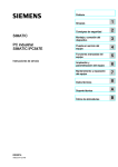
L1 and L2 POS Motherboard (with BIOS Setup) User Manual We would like to know your opinion on this publication. Please send us a copy of this page if you have any constructive criticism. We would like to thank you in advance for your comments. With kind regards, Your opinion: Wincor Nixdorf International GmbH Documentation R&D SAT 11 Wohlrabedamm 31 D-13629 Berlin E-Mail: [email protected] Order No.: 010750266922A L1 and L2 POS Motherboard User Manual Edition November 2014 All brand and product names mentioned in this document are trademarks of their respective owners. Copyright © Wincor Nixdorf International GmbH, 2014 The re production, transmission or use of this document or its contents is not permitted without express authority. Offenders will be liable for damages. All rights, including rights created by patent grant or registration of a utility model or design, are reserved. Delivery subject to availability; technical modifications possible. Contents Overview ....................................................................................... 1 Introduction ....................................................................................... 1 Some Highlights of the L1 and L2 Motherboard ................................ 1 Motherboard Specification ............................................................ 3 Block Diagram .................................................................................... 3 Internal Connectors ........................................................................... 4 Mainboard assembly variants ............................................................ 5 CPU support ....................................................................................... 5 Mainboard internal connectors and onboard features ..................... 5 USB 2.0 (internal) .......................................................................... 5 Mini PCI Express ............................................................................ 6 Memory (internal) ......................................................................... 7 SATA (internal) .............................................................................. 7 Fan (internal) ................................................................................. 7 Chassis intrusion connector (internal)........................................... 8 Front panel connector (internal) ................................................... 8 ATX / 12V Power connector (internal) .......................................... 9 LPT (internal) ............................................................................... 10 TPM (onboard) ............................................................................ 10 PCI Express Slots (internal) .......................................................... 11 Mainboard onboard connectors with external access .................... 12 Motherboard I/O shield overview (external) .............................. 12 DVI-D (external) ........................................................................... 12 VGA (external) ............................................................................. 12 LAN (external).............................................................................. 12 USB 2.0 / USB 3.0 (external) ........................................................ 12 COM (external) ............................................................................ 13 Audio (external) ........................................................................... 13 Technical Data ............................................................................. 14 Supported Sleep States .................................................................... 15 Changing the Battery ................................................................... 17 UEFI BIOS Setup ........................................................................... 18 Standard UEFI BIOS Version ............................................................. 18 BIOS Menu Bar ................................................................................. 19 Legend Screen .................................................................................. 19 General Help .................................................................................... 20 Scroll Bar .......................................................................................... 20 Sub-Menu ......................................................................................... 21 Info Screen ....................................................................................... 21 Product Name: ............................................................................. 22 BIOS Version: ............................................................................... 22 Ethernet MAC Address: ............................................................... 22 UUID Info: .................................................................................... 22 System, Main board, Power Supply: ............................................ 22 Main Menu .................................................................................. 23 System Date [MM/DD/YYYY] ........................................................... 23 System Time [XX: XX: XX] ................................................................. 23 Processor and Chipset Information.................................................. 23 Advanced Menu ........................................................................... 24 Sub Menu ACPI Settings ............................................................... 24 Enable ACPI Auto Configuration .................................................. 25 Sub Menu Trusted Computing ..................................................... 25 Security Device Support [Disable] ............................................ 25 TPM State [Disabled] ................................................................ 25 Pending operation [None] ....................................................... 25 Sub Menu Hardware Configuration ............................................. 26 PCH LAN Controller [Enabled] .................................................. 26 Launch PXE OpROM policy [Do not launch] ............................. 26 Wake On LAN [Disabled] .......................................................... 26 Wake On Ring [Disabled].......................................................... 26 Wake On USB/PS2 [Disabled]................................................... 27 Wake On PCIe Slot [Disabled] .................................................. 27 Wake-on Modes .......................................................................... 27 Restore AC Power Loss [Follow AC Power] .............................. 27 Bootorder Menu [Enabled] ...................................................... 28 Sub Menu CPU Configuration ...................................................... 28 Hyper-threading [Enabled]....................................................... 28 Active Processor Cores [All] ..................................................... 29 Overclocking lock [Disabled] .................................................... 29 Limit CPUID Maximum [Disabled] ............................................ 29 Execute Disable Bit [Enabled] .................................................. 29 Intel Virtualization Technology [Enabled] ................................ 29 Hardware Prefetcher [Enabled] ............................................... 29 Adjacent Cache Line Prefetch [Enabled] .................................. 30 CPU AES * [Enabled] ................................................................ 30 Boot performance mode [Max Non-Turbo Performance] ....... 30 EIST [Enabled] .......................................................................... 30 Turbo Mode * [Enabled] .......................................................... 30 Intel TXT (LT) Support * [Enabled] ........................................... 30 Sub Menu SATA Configuration .................................................... 31 SATA Controller(s) [Enabled] ................................................... 31 SATA Mode selection [IDE] ...................................................... 31 SATA 0, 1, 5 .................................................................................. 31 SATA 4 ......................................................................................... 32 Sub Menu Platform Thermal Configuration ................................ 32 Automatic Thermal Reporting [Enabled] ................................. 32 Active Trip Point 0 Fan Speed 100 ........................................... 32 Active Trip Point 1 [55 C] ......................................................... 32 Active Trip Point 1 Fan Speed 75 ............................................. 33 Passive TC1 Value 1.................................................................. 33 Passive TC2 Value 5.................................................................. 33 Passive TSP Value 10 ................................................................ 33 PCH Thermal Device [Disabled] ............................................... 33 Sub Menu PCH-FW Configuration................................................ 34 Intel ME (Management Engine) Subsystem ................................ 34 MEBx Type [None] ................................................................... 34 MDES BIOS State Code [Disabled] ........................................... 34 Sub Menu AMT Configuration ..................................................... 35 Intel AMT [Enabled] ................................................................. 35 BIOS Hotkey Pressed [Disabled]............................................... 35 MEBx Selection Screen [Disabled] ........................................... 36 Hide Un-Configure ME Confirmation [Disabled] ...................... 36 MEBx Debug Message Output [Disabled] ................................ 36 Un-Configure ME [Disabled] .................................................... 36 AMT Wait Timer 0 .................................................................... 36 Disable ME [Disabled] .............................................................. 36 ASF [Enabled] .......................................................................... 36 Activate Remote Assistance Process [Disabled] ...................... 36 USB Configure [Enabled] .......................................................... 36 PET Progress [Enabled] ............................................................ 36 WatchDog [Disabled] ............................................................... 37 Sub Menu USB Configuration....................................................... 37 Legacy USB Support [Enabled] ................................................. 37 USB3.0 Support [Enabled] ........................................................ 37 XHCI Hand-off [Enabled] .......................................................... 38 EHCI Hand-off [Enabled] .......................................................... 38 USB Ports Per-Port Disable Control [Enabled] ......................... 38 USB Mass Storage Driver Support [Enabled] ........................... 38 PORT 60/64 Emulation [Enabled]............................................. 38 Sub Menu NTC6106D Super IO Configuration ............................. 38 Parallel Port Configuration .......................................................... 39 Sub Menu NTC6106D H/W Monitor ............................................ 39 Sub Menu Serial Port Console Redirection .................................. 40 Console Redirection [Enabled] ................................................. 40 Sub Menu CMOS...................................................................... 41 Sub Menu Intel(R) Ethernet Network Connection .................. 42 Chipset Menu ................................................................................... 43 Sub Menu PCH-IO Configuration ............................................. 43 Sub Menu System Agent (SA) Configuration ........................... 44 Boot Menu ....................................................................................... 46 Quiet Boot [Disabled] ............................................................... 47 Fast Boot [Disabled] ................................................................. 47 Boot mode select [LEGACY] ..................................................... 47 Fixed Boot Order Priorities ‘#n’ Boot Device ............................... 47 Security Menu .................................................................................. 48 Administrator Password .............................................................. 48 Intrusion Detection [Disabled] ................................................ 48 Sub Menu Security Menu Secure Boot menu ..................... 49 Save & Exit Menu ............................................................................. 50 Discard Changes and Exit ............................................................. 50 Save Changes and Reset .............................................................. 50 Discard Changes and Reset .......................................................... 51 Restore Defaults .......................................................................... 51 Boot Override .............................................................................. 51 Launch EFI Shell from File System Device .................................... 51 Test Points Codes ............................................................................. 51 Checkpoint Ranges ...................................................................... 51 SEC Phase..................................................................................... 52 PEI Phase ..................................................................................... 52 PEI Beep Codes ............................................................................ 55 DXE Phase .................................................................................... 55 DXE Beep Codes .......................................................................... 58 Abbreviations .............................................................................. 59 Overview Introduction This manual describes the features of two variants of a Motherboard based on the Intel 8 series chipset Q87 and H81, formerly known as Lynx Point. These L1 and L2 Motherboards were primarily designed for the Wincor Nixdorf Systems EPC_5G, EPC_5G_DC and EPC_5G_Upgrade. Some Highlights of the L1 and L2 Motherboard 4th Generation Intel® Core™ Processors, formerly known as Haswell Intel 8 series chipset Q87 and H81, formerly known as Lynx Point CPU integrated graphic controller up to Intel® HD Graphics 4600, depending on used processor AMT 9.1 support at L1 motherboards 1x VGA Interface 1x DVI-D interface Gigabit LAN onboard (Intel® Ethernet Connection; Q87: I217-LM, H81: I217-V) 3 SATA ports (Q87: 3xSATA III, H81: 2x SATA III + 1x SATA II) 2x DDR3 SODIMM sockets, supporting up to 16GB (2x8GB) at 1600MHz. Only ~3GB available for 32bit OS 1x PCI Express x16 gen3 2x PCI Express x1 gen2 2 Standard COM ports 1 LPT port L1 and L2 Motherboard, User Manual 1 MiniPCIe socket (full size) supporting the WN NVRAM module 2 USB3.0 ports Q87: 12 USB2.0 ports, H81: 8x USB ports TPM onboard PC Beeper onboard TFT- displays without DDC are not supported. 2 L1 and L2 Motherboard, User Manual Motherboard Specification Block Diagram DVI Level Shifter PI3VDP411 DVI-D LGA 1150 Haswell + Haswell Refresh CPU 65W TDP max. PCI Express x16 2x DDR3 SODIMM Socket FDI DMI PCIe x16 Dual Channel DDR3 VGA PCI Express x1 VGA 2x PCIe x1 Slot HD Audio Link SATA II/III 3x SATA Ports Up to 12 USB2.0 Ports Lynx Point PCH Q87 / H81 USB2.0 PCI Express x1 USB3.0 PCI Express x1 2x USB3.0 Ports LPC LPC 1Gb LAN I217LM /1217V miniPCIe LPC SPI HD Audio Codec ALC662 TPM COM BIOS 64 / 128Mbit L1 and L2 Motherboard, User Manual SIO NCT6106D COM 1+2 LPT LPT 3 4 JP3 JP4 Internal Connectors L1 and L2 Motherboard, User Manual Mainboard assembly variants As mentioned above there are two motherboard variants: The L1 board with Q87 chipset supporting AMT and RAID and the L2 board with H81 chipset as value edition supporting lesser features. CPU support CPU CPU# i5 #CPU core #Threads GHz Core i5-4570TE 2 4 i5 i5-4570S 4 i3 GHz GFX Cache size TDP [W] 2.7 (3.3) 0.35 (1) 4MB 35 4 2.9 (3.6) 0.35(1.15) 6MB 65 i3-4330TE 2 4 2.4 0.35 (1) 4MB 35 i3 i3-4330 2 4 3.5 0.35 (1.15) 4MB 54 Pentium G3320TE 2 2 2.3 0.35 (1) 3MB 35 Pentium G3420 2 2 3.2 0.35 (1.15) 3MB 53 Celeron G1820TE 2 2 2.2 0.35 (1) 2MB 35 Celeron G1820 2 2 2.7 0.35 (1.05) 2MB 53 Mainboard internal connectors and onboard features USB 2.0 (internal) 6 USB ports at L1 board and 2 USB ports at L2 are routed to 10pin double row headers with 2.54 mm pitch. Each header provides 2 ports. These headers are intended to connect optional front USB modules or USB hubs. Two USB ports share one fuse. USB port 11 at header USB3 (pins 1,3,5,7) is shared with PCIe x1 connector PCIE3 (pins A5 to A8) for USB uplink connection for the "Retail Card". L1 and L2 Motherboard, User Manual 5 Mini PCI Express The mainboard provides a full size mini PCI Express (rev.1.1) / mSATA connector. It is placed on top, thus being accessable without removing other components. It supports LPC signals including serial interrupts. Auto detection by mSATA presence detect supports automated switch between mSATA and PCIe functionality (PCIe functionality only supported in conjunction with Q87 chipset according to mini PCI Express Standard Rev 1.1). The L1 motherboard supports PCIe and mSATA functionality, the L2 motherboard supports mSATA functionality only. Connector type: Standard MiniPCIe 1.1 connector full size Pin 1 3 5 7 9 11 13 15 17 19 21 23 25 27 29 31 33 35 37 39 41 43 45 47 49 51 6 Function WAKE n.c. n.c. CLKRQ# GND REFCLKREFCLK+ GND SUSCLK 32KHz CLK 33MHz GND PCIE_RX- / SATA +B PCIE_RX+ / SATA -B GND GND PCIE_TX- / SATA -A PCIE_TX+ / SATA +A GND GND VCC3 VCC3 GND n.c. n.c. n.c. mSATA presence detect Pin 2 4 6 8 10 12 14 16 18 20 22 24 26 28 30 32 34 36 38 40 42 44 46 48 50 52 Function VCC3 GND VCC 1.5V FRAME# LAD3 LAD2 LAD1 LAD0 GND n.c. RESET# 3VSB GND VCC 1.5V SMB_CLK SMB_DATA GND n.c. (USB-) n.c. (USB+) GND n.c. n.c. n.c. VCC 1.5V GND VCC3 L1 and L2 Motherboard, User Manual Memory (internal) The mainboard provides two DDR3 SODIMM sockets supporting up to 16GB in dual channel mode. The horizontal mounting of the SODIMM sockets ensures an optimal air flow. SATA (internal) The mainboard provides three standard SATA ports. The ports SATA1 (white) and SATA2 (blue) supporting SATA III connectivity speed. Port SATA3 (black) supports SATA III speed at L1 board, and SATA II speed at L2 board. The RAID functionality is only supported by the L1 motherboard. Fan (internal) The mainboard provides two fan connectors. The CPU fan connector supports PWM fans with 4 pin connection. Connector details are: 2.54mm (.100") Pitch Vertical Header, with Friction Lock, 4 (3) Circuits, PC Tail Length: 3.50mm (.138"). Molex Part Nr: 470531000 or similar. The connector follows the Intel “4-Wire Pulse Width Modulation (PWM) Controlled Fans” specification. PWM Fan Pin Signal 1 GND 2 12 V 3 Sense 4 Control Signal Description GND Fan operation voltage Tachometric signal PWM control signal (only 4 pin connector) The PSU fan connector has 3 pin connection with DC fan speed regulation. DC Fan Pin 1 2 3 Signal GND PWR Sense Signal Description GND Operation Voltage 6-12 V Tachometric signal L1 and L2 Motherboard, User Manual 7 Chassis intrusion connector (internal) The mainboard supports a chassis intrusion connector. Type: 3 pin shrouded header, B3B-PH-K-S (JST) or equivalent. Pin Number 1 2 3 Function GND Intrusion input (switch to GND if chassis is open) n.c. Front panel connector (internal) The mainboard supports a front panel connector to support service elements (like POWER ON pushbutton, HDD and power LEDs). The Power LED at the chassis front connected to this front panel header is green when system is powered on (S0). During Stand By (S3) it blinks green and when system is in hibernation (S4) or powered down (S5) the LED is orange. Power Status S0 S3 S4, S5 Power LED Green Green blinking Orange The BIOS is able to disable the power button. This feature is automatically enabled when "Follow AC power" is selected within the BIOS setup. Then it is not possible to switch off the system by the power button, even when pressed longer than 4s. But when the OS is shut down correctly, system can be switched on again by the power button. The front panel header also supports speaker connection. 8 L1 and L2 Motherboard, User Manual Type: 2x6 pin header, 2.54 mm pitch. Pin Number 1 2 3 4 5 6 7 8 9 10 11 12 Function Power switch + Reset switch + Power switch Reset switch Power LED + Speaker Power LED Coding HDD LED + GND HDD LED Speaker + ATX / 12V Power connector (internal) The mainboard provides a 4 pin and a 24 pin ATX power connector. Pin Number 1,2,12,13 3,5,7,15,17,18,19,24 4,6,21,22,23 8 9 10, 11 14 16 20 Function +3.3V GND +5V Power ok 5V SB +12V -12V PSON n.c. Pin Number 1,2 3,4 Function GND +12V A 20 pin ATX power cable can be plugged into the 24 pin connector on the motherboard, too. In this case the pins 11,12,23 and 24 are not used and L1 and L2 Motherboard, User Manual 9 left open. The 4 pin ATX power connector has to be connected to the PSU anyway, otherwise the motherboard will not work. LPT (internal) Connector type: 26 pin shrouded header, 2.54mm pitch Pin 1 2 3 4 5 6 7 8 9 10 11 12 13 Function STR# AFD# D0 ERR# D1 PINIT# D2 LPT_SLIN# D3 GND D4 GND D5 Pin 14 15 16 17 18 19 20 21 22 23 24 25 26 Function GND D6 GND D7 GND ACK# GND BUSY GND PE GND SLCT Key TPM (onboard) PP JP3 JP4 1 2 3 1 2 3 TPM The mainboard provides the Infineon SLB 9635 TT 1.2 Trusted Platform Module (TPM) with firmware 3.19 directly soldered on the PCB. Jumper 4 (JP4): Enables/Disables the TPM Chip. Default setting is position 1-2, TPM enabled. To disable the TPM set Jumper to position 2-3. 10 L1 and L2 Motherboard, User Manual Jumper 3 (JP3): Sets the physical presents (PP). Default setting is position 2-3, PP disabled. To enable PP set Jumper to position 1-2. PCI Express Slots (internal) There are two PCIe slots x1 and one 1 PCIe slot x16. Use in the systems BEETLE /MIII, EPC_5G, EPC_5G_DC or EPC_5G_Upgrade Only low profile cards are supported. Height 68.90 mm (2.731 inches) maximum, Length 167.65 mm (6.600 inches) maximum PCIe cards are able to wake up the system. Thermal management: The input power of a single PCIe x1 card must not exceed 10W and x16 card does not exceed 30W. The PCIe slot at the outer side of the mainboard supports USB signals on PCIe pins A5 (D-) and A8 (D+) as USB uplink connection and A6+A7 (VBUS) to Retail specific PCIe card. The same USB port is routed to the USB3 connector. Onboard power button and status LED (internal) The motherboards support one onboard power button in rear I/O shield area. The button’s position protects it from being touched accidentally or being pushed by cables. The motherboards support 2 dual color onboard LEDs indicating the power status (green) and HDD activity (red). The LEDs are visible outside of the chassis through a chassis hole. Power status S0 S3, S4, S5 Power LED Green Off Onboard status LEDs and power button work together with an external status LED and power button connected to the front panel connector. L1 and L2 Motherboard, User Manual 11 Mainboard onboard connectors with external access Motherboard I/O shield overview (external) The picture below shows the arrangement of the onboard I/O connectors. DVI-D (external) This intervace uses a standard DVI-D connector supporting a single link connection to a digital display. Only displays with DDC are supported. VGA (external) This interface uses a 15 pin DSUB connector in the upper row of I/O shield. Sync signals VSYNC and HSYNC have 5V logic high level. LAN (external) The mainboard supports 1Gbit connection to a Local Area Network (LAN). Indication LED for link and activity is available. Right LED 10mbit 100mbit 1000mbit Left LED Link at every speed Traffic at every speed Speed Indication off green orange Link&Activity Yellow on Yellow blinking WOL (wake on LAN) and PXE are supported. USB 2.0 / USB 3.0 (external) 8 USB ports (6 for USB2.0 and 2 for USB3) are located in the mainboard I/O connector area. 12 L1 and L2 Motherboard, User Manual COM (external) There are two standard RS232 COM ports (male 9pin DSUB connectors) at the I/O shield. Audio (external) The mainboard supports a microphone-in, a line-out and a line-in connector in I/O shield. The connector type is stereo 3.5mm diameter. L1 and L2 Motherboard, User Manual 13 Technical Data Topic Form Factor Processor Chipset CPU Socket Graphics Main Memory Storage LAN Audio USB Expansion Slots Motherboard External I/O Connectors (at I/O Shield) 14 Remarks µATX 226x210mm 4th Generation Intel® Core™ Processors Intel Series 8 (L1: Q87; L2: H81) LGA1150 Celeron 1820: Intel HD Graphics Core i3: Intel HD 4600 Core i5: Intel HD 4600 Dual channel memory architecture 2 sockets supporting unbuffered non-ECC DDR3 memory modules supporting up to 16GB system memory SODIMM 3x SATA III (L1) 2x SATA III + 1x SATA II (L2) RAID support (L1 only) onboard Gigabit LAN, status LED activity and link Realtek HD audio Codec ALC 662 2x USB 3.0 12x USB 2.0 (L1) 8x USB 2.0 (L2) 2x PCIe x1 1x PCIe x16 slot 1x MiniPCIe 1.1 (used by L1 only), additional LPC signals 1x DVI-D Audio: 1x LAN (RJ45) + 2x USB3.0 Line in (blue) 6x USB2.0 Line out (green) 1x VGA Microphone in (pink) 1x COM 1x Power Button and Status LED L1 and L2 Motherboard, User Manual Internal I/O Con- 3x USB 2.0 headers supporting 2 ports each (L1) nectors 1x USB 2.0 headers supporting 2 ports each (L2) 1x PCIe x16 2x PCIe x1 1x MiniPCIe, v1.1 2x DDR3 SODIMM 3x SATA 1x CPU fan 4pin 1x PSU fan 3pin 1x LPT header 1x Chassis intrusion 1x 24pin ATX 1x 4pin ATX 1x Front panel header Other Special 1x CMOS clear jumper Features TPM onboard Buzzer (PC Beeper) onboard Product Lifecycle 5 years without changing OS software driver critical components e.g. audio codec, LAN, Super-I/O, Chipset AMT Version 9.1 at L1 board only MTBF ca. 400.000h Hardware Monitor The requirements for the hardware monitoring are described in the BIOS chapter Hardware Monitor. Supported Sleep States S0 S3 S4 S5 Normal Operation (“ON”) Suspend to RAM / “Stand By” Suspend to Disk / “Hibernation” Soft Off RAID (L1 Motherboard) The L1 motherboard provides RAID functionality for the SATA interface. Raid level 0 (striping), 1 (mirroring) and 5 (striping with distributed parity) are supported. For RAID 5 three HDD/SSD devices are needed. L1 and L2 Motherboard, User Manual 15 To enable the RAID functionality please see the corresponding chapter in the BIOS setup description. For SATA ports 1 and 2 there are onboard LEDs indicating the status of the attached HDD/SSD within the RAID Array. The functionality of the SATA LEDs depends on host software (Intel SATA/RAID driver (“Rapid Storage Technology” – driver at the time of writing)). The host software needs to be installed and running for LED indication to work. LED D3 D4 D5 D6 16 Color Yellow Yellow Red Red D3 SATA 2 D4 D6 D5 SATA 3 SATA 1 Function Read/Write activity indication for SATA2 port Read/Write activity indication for SATA1 port Failure indication for SATA2 port Failure indication for SATA1 port L1 and L2 Motherboard, User Manual Changing the Battery The systems are equipped with a lithium battery on the motherboard to ensure data retention, the time and the setup parameters. The battery should be changed approximately every five years. When inserting the new battery, make sure the polarity is correct. This is marked in the socket. Incorrect replacement of the battery may lead to the danger of explosion. The battery is located in a socket on the Motherboard. To gain access to the battery, proceed as described in the according chapters of your BEETLE User Manual. See: http://www.wincor-nixdorf.com/internet/site_EN//EN/Support/ Downloads/POSLotterySystems/Manuals/manuals_node.html The lithium battery must be replaced only by identical batteries or types recommended by Wincor Nixdorf International. You can return the used batteries to your Wincor Nixdorf International sales outlet. Batteries containing harmful substances are marked accordingly. The chemical denotations are as follows: CD = Cadmium; Pb = Lead, Li = Lithium. This symbol on a battery tells you that batteries containing harmful substances must not be disposed of as household waste. Follow the country specific laws and regulations. Within the European Union you are legally bound to return these batteries to the service organization where you purchased the new battery. The setup parameters must be reset each time the battery has been changed. L1 and L2 Motherboard, User Manual 17 UEFI BIOS Setup The mainboard L1.0-Q87-uATX-STD and L2.0-H81-uATX-STD comes with an AMI UEFI BIOS chip that contains the ROM Setup information of your system. This chip serves as an interface between the processor and the rest of the mainboard’s components. This section explains the information contained in the Setup program and tells you how to modify the settings according to your system configuration. Even if you are not prompted to use the Setup program, you might want to change the configuration of your system in the future. For example, you may want to enable the Security Password Feature or make changes to the power management settings. It will then be necessary to reconfigure your system using the BIOS Setup program so that the system can recognize these changes and record them in the NVRAM. All setup data is stored in a non-volatile memory (NVRAM). When you remove the battery, all parameters will be lost. Standard UEFI BIOS Version The UEFI BIOS ROM of the system holds the Setup utility. When you turn on the system, it will provide you with the opportunity to run this program. This appears during the Power-On Self-Test (POST). Press <F2> to call the Set-up utility. If you are a missed the opportunity to pressing the mentioned key, POST will continue with its test routines, thus preventing you from calling Setup. If you still need to call Setup, reset the system by pressing <Ctrl> + <Alt> + <Del>. You can also restart by turning the system off and then on again. But do so only if the first method fails. If you like to change the boot order only once, you can press the <F10> key during the POST is running. At the end you will see a Pop-Up window with all the devices the system has found. With the keys <UP> and <DOWN> you select the boot device. The Setup program has been designed to make it as easy as possible. It is a menu-driven program, which means you can scroll through the various sub-menus and make your selections among the predetermined choices. 18 L1 and L2 Motherboard, User Manual When you invoke Setup, the main program screen will appear. Read more about the Setup entries on the following pages. Because the UEFI BIOS software is constantly being updated, the following UEFI BIOS screens and descriptions are for reference purposes only and may not reflect your UEFI BIOS screens exactly. BIOS Menu Bar The top of the screen has a menu bar with the following sections: Info Main Advanced Chipset Boot Security Save & Exit Use this menu for information only Use this menu to make changes to the basic system configuration. Use this menu to enable and make changes to the advanced features. Use this menu to configure the chipset specific options Use this menu to configure the default system device used to locate and load the Operating System. Use this menu to enable a supervisor or user password and Intrusion Detection. Use this menu to exit the current menu or specify how to exit the Setup program. To access the menu bar items, press the right or left arrow key on the keyboard until the desired item is highlighted. Legend Screen The right frame displays the key legend. The keys in the legend frame allow you to navigate through the various setup menus. The following table lists the keys found in the legend with their corresponding alternates and functions. L1 and L2 Motherboard, User Manual 19 Navigation Key(s) ← or → (keypad arrows) ↑ or ↓ (keypad arrows) Enter + (plus key) - (minus key) <Tab> <F1> <F2> <F3> <F4> <Esc> Description of Functions Select the menu item to the left or right. Moves the highlight up or down between fields. Move into sub menu or change selected menu items Change field contents. Jumps from one field to the next. Opens a general Help Screen with extended information. Load previous values (Load last saved values) Load optimized values (Factory reset) Saves changes and exits Setup. Opens a windows to select between exit and return to setup General Help In addition to the Item Specific Help window, the UEFI BIOS setup program also provides a General Help screen. This screen can be called from any menu by simply pressing <F1>. The General Help screen lists the legend keys with their corresponding alternates and functions. Scroll Bar When a scroll bar appears to the right of a help window, it indicates that there is more information to be displayed that will not fit in the window. Use <PgUp> and <PgDn> or the up and down keys to scroll through the entire help document. Press <Home> to display the first page, press <End> to reach the last page. To exit the help window, press the <Enter> or <Esc> key. 20 L1 and L2 Motherboard, User Manual Sub-Menu Note that a right pointer symbol “” appears left of certain fields. This pointer indicates that a sub-menu can be launched from this field. A sub-menu contains additional options for a field parameter. To call a sub-menu, simply move the highlight to the field and press <Enter>. The sub-menu then will appear immediately. Use the legend keys to enter values and move from field to field within a sub-menu just as you would do within a menu. Use the <Esc> key to return to the main menu. Take some time to familiarize yourself with each of the legend keys and their corresponding functions. Practice navigating through the various menus and sub-menus. If you accidentally make unwanted changes to any of the fields, use the set default hot key <F3>. While moving around through the Setup program, note that explanations appear in the Item Specific Help window located to the right side of each menu. This window displays the help text for the currently highlighted field. Info Screen When the Setup program is accessed, the following info screen appears: Wincor Nixdorf Info Page Product Name: Bios Version: Bios Date: Ethernet MAC-Address: UUID: d716af80-6f0a-1018-8789-fbd248a1242f System: --------------------------- --- -----------------------------###--------------------------------------------------------Mainboard: --------------------------- --- -------------------------------------------------------------------------------------------Power Supply: --------------------------- --- --------------------------------------------------------------------------------------------L1 and L2 Motherboard, User Manual #.#-###-uATX-STD xx/yy MM/DD/YYYY AC-DC-FA-DE-BE-EF 21 This screen is for information only. There is nothing that could be changed within Setup. All information is intended to facilitate the support of your system. Product Name: This text is fixed for your mainboard with standard UEFI BIOS. This board is also called “L1.0-Q87-uATX-STD” or “L2.0- H81-uATX-STD” BIOS Version: The UEFI BIOS version is displayed in the WN release format xx/yy The UEFI BIOS Date is displayed the date of release in international format: MM/DD/YYYY Ethernet MAC Address: The Ethernet MAC-Address of the on board LAN Controller is displayed at this line if this device is enabled. UUID Info: A UUID is an identifier standard used in software construction, standardized by the Open Software Foundation. The intent of UUIDs is to enable distributed systems to uniquely identify information without significant central coordination. System, Main board, Power Supply: The default placeholders may be replaced by specific data from factory, describing configuration, serial number etc. for each device. 22 L1 and L2 Motherboard, User Manual Main Menu BIOS Information Bios Vendor Compliancy American Megatrends UEFI 2.3.1; PI 1.2 Total Memory Memory Frequency 2048 MB (DDR3) 1333 MHz System Date System Time [Mo 07/07/2014] [23:23:23] Processor and Chipset Information System Date [MM/DD/YYYY] Set your system to the date that you specify (usually the current date). The format is month, day, year. Valid values for month, day and year are: Month: (1 to 12), Day (1 to 31), Year: (up to 2079). System Time [XX: XX: XX] Set your system to the time that you specify (usually the current time). The format is hour, minute, second. Valid values for hour, minute, and second are: Hour: (00 to 23), Minute: (00 to 59), Second: (00 to 59). Press <Enter> to terminate every entry value and reach the next position. On the upper right frame find the keys listed to modify the values. Processor and Chipset Information This enters a Sub-Menu with summaries of used processor and chipset. L1 and L2 Motherboard, User Manual 23 Advanced Menu ACPI Settings Trusted Computing Hardware Configuration CPU Configuration SATA Configuration Thermal Configuration PCH-FW Configuration AMT Configuration USB Configuration NCT6106D Super IO Configuration NCT6106D HW Monitor Serial Port Console Redirection CMOS Intel(R) Ethernet Network Connection Sub Menu ACPI Settings ACPI Settings Enable ACPI Auto Configuration 24 [Enabled] L1 and L2 Motherboard, User Manual Enable ACPI Auto Configuration Being an ACPI BIOS system, the operating system is allowed to control the Power Management features of the computer and the setting for Advanced Power Management (APM) BIOS mode are ignored. Not all operating systems support ACPI BIOS mode. Sub Menu Trusted Computing Configuration Security Device Support TPM State Pending Operation [Enable] [Disabled] [None] Current Status Information TPM Enabled Status TPM Active Status [Disabled] [Deactivated] Security Device Support [Disable] This option enables or disables the Trusted Platform Module. After change this option the system will reboot automated. If the security device is disabled the OS will not show this device in device list. TPM State [Disabled] This option changes the actual state of the security module. Select the TPM operation after the next automated reboot of the system. Pending operation [None] [None]: The TPM state will be untouched. L1 and L2 Motherboard, User Manual 25 Sub Menu Hardware Configuration PCH LAN Controller Launch PXE OpROM policy [Enabled] [Do not launch] Wake On LAN Wake On Ring Wake On USB/PS2 Wake On PCIe Slot [Disabled] [Disabled] [Disabled] [Disabled] Restore AC Power Loss BootOrder Menu VT-d [Follow AC Power] [Enabled] [Enabled] PCH LAN Controller [Enabled] This option allows enabling or disabling the on-board LAN controller. Configuration options: [Disabled] [Enabled]. Launch PXE OpROM policy [Do not launch] Preboot Execution Environment (PXE) refers a method to boot up over network without the need for a hard drive or boot diskette. Configuration options: [Do not launch] [UEFI only] [Legacy only]. Wake On LAN [Disabled] This allows enabling or disabling power up the BEETLE when the LAN controller receives a call while the BEETLE is in Soft-Off or Hibernate mode. Configuration options: [Disabled] [Enabled]. Wake On Ring [Disabled] This allows enabling or disabling power up the BEETLE when the modem receives a call while the BEETLE is in Soft-Off or Hibernate mode. The BEETLE cannot receive or transmit data until the system and applications are fully running, thus connection cannot be made on the first try. Turning an external modem off and then 26 L1 and L2 Motherboard, User Manual back on while the BEETLE is off causes an initialization string that will cause the system to power on. Configuration options: [Disabled] [Enabled]. Wake On USB/PS2 [Disabled] This allows enabling or disabling power up the BEETLE when a USB- or a PS2- Keyboard/Mouse receives a call while the BEETLE is in Soft-Off mode. Configuration options: [Disabled] [Enabled]. Wake On PCIe Slot [Disabled] This allows enabling or disabling power up the BEETLE when a device mounted in a PCIe slot receives a call while the BEETLE is in Soft-Off or Hibernate mode. Configuration options: [Disabled] [Enabled]. Wake-on Modes Please note that you have to shut down the system in power saving modes by OS before you can use Wake-on modes. Switching off the system by main power switch or front button-override will not initialize system wakeup functions. See following table, which wakeup events are available from different power states: Standby (S3) Hibernate (S4) Soft off (S5) Front Button Yes Yes Yes LAN (Note1) Yes Yes Yes Modem (Note2) Yes Yes Yes USB/PS2 (Note3) Yes No No PCIe Slot (Note4) Yes Yes Yes Note 1: “Yes” is valid only, if the option <Wake on LAN> is [Enabled]. Note 2: “Yes” is valid only, if the option <Wake on Ring> is [Enabled]. Note 3: “Yes” is valid only, if the option <Wake on USB/PS2> is [Enabled]. Note 4: “Yes” is valid only, if the option <Wake on PCIe Slot> is [Enabled]. Restore AC Power Loss [Follow AC Power] Select the options to reboot the system after power has been interrupted. [Power off] leaves the system off until pressing the power button. [Last State] reboots the system automatically if it was active before power loss. [Follow AC Power] will start up anytime power is available. Configuration options: [Power off] [Last State] [Follow AC Power]. L1 and L2 Motherboard, User Manual 27 Bootorder Menu [Enabled] This option enables or disables the popup menu to change the boot order by pressing F10 during POST. [Enabled] Popup menu is available during POST [Disabled] Popup menu is not available during POST Sub Menu CPU Configuration Items marked with ‘ * ’ are not available by all Intel processors CPU Configuration Intel (R) Core (TM) i3-4330TE CPU 2.40GHz Hyper-threading Active Processor Core Overcklocking lock Limit CPUID Maximum Execute Disable Bit Intel Virtualization Technology Hardware Prefetcher Adjacent Cache Line Prefech Boot performance mode EIST Turbo Mode* Intel TXT(LT) Support CPU Configuartion Parameters Hyper-threading [Enabled] [Enabled] [All] [Disabled] [Disabled] [Enabled] [Enabled] [Enabled] [Enabled] [Max Non-Turbo Per….] [Enabled] [Enabled] [Disabled] [Enabled] This option allows enabling or disabling the Intel(R) Hyper-threading Technology to uses processor resources more efficiently, enabling multiple threads to run on each core. Configuration options: [Disabled] [Enabled]. 28 L1 and L2 Motherboard, User Manual Active Processor Cores [All] This option enables all or several cores of an Intel processor. The numbers of cores are depends of used processor type. Configuration options: [All] [Number of cores 1-x]. Overclocking lock [Disabled] This option enables or disables the overclocking feature of an Intel processor. Configuration options: [Disabled] [Enabled]. Limit CPUID Maximum [Disabled] When CPUID instruction is executed, newer CPU may return a value greater than 3 which cause a certain problem with specific operating systems. Enabling "Limit CPUID Maximum“ will limit the returned value to 3 (and less) to get rid of the problem. The problem does not occur with Windows series operating systems. Configuration options: [Disabled] [Enabled] Execute Disable Bit [Enabled] Execute Disable Bit (EDB) is an Intel© Hardware-based security feature that can help reduce system exposure to viruses and malicious code. EDB allows the processor to classify areas in memory where application code can or cannot execute. Configuration options: [Disabled] [Enabled] Intel Virtualization Technology [Enabled] Virtualization enhanced by Intel© Virtualization Technology will allow a system to run multiple operating systems and applications in independent partitions. With virtualization, one computer system can function as multiple “virtual” systems. Configuration options: [Disabled] [Enabled] Hardware Prefetcher [Enabled] The processor has a hardware prefetcher that automatically analyses its requirements and prefetches data and instructions from the memory into the Level 2 cache. This reduces the latency associated with memory reads. Configuration options: [Disabled] [Enabled] L1 and L2 Motherboard, User Manual 29 Adjacent Cache Line Prefetch [Enabled] The processor has a hardware adjacent cache line prefetch mechanism that automatically fetches an extra 64-byte cache line whenever the processor requests for a 64-byte cache line. This reduces cache latency by making the next cache line immediately available if the processor requires it as well. Configuration options: [Disabled] [Enabled] CPU AES * [Enabled] This option enables or disables the CPU Advanced Encryption Standard instructions. Configuration options: [Disabled] [Enabled] Boot performance mode [Max Non-Turbo Performance] This option adjusts the performance of Boot mode. Configuration options: [Max Non-Turbo Performance] [Max Battery] [Turbo Performance] EIST [Enabled] This option enables or disables the Enhanced Intel SpeedStep Technology of an Intel processor. Configuration options: [Disabled] [Enabled]. Turbo Mode * [Enabled] This option enables or disables the Turbo Mode of several Intel processors. Configuration options: [Disabled] [Enabled] Intel TXT (LT) Support * [Enabled] Intel Trusted Execution Technology (TXT) is supported by several Intel processors. Configuration options: [Disabled] [Enabled] 30 L1 and L2 Motherboard, User Manual Sub Menu SATA Configuration SATA Controllers SATA Mode selection SATA 0 (white) [Enabled] [IDE] Empty SATA 1 (blue) Empty SATA 4 (mSATA) Empty SATA 5 (black) Empty SATA Controller(s) [Enabled] This option enables or disables the SATA controller. Configuration options: [Disabled] [Enabled]. SATA Mode selection [IDE] This option selects the SATA controller mode. The option [RAID] is only available on L1 boards with Q87 Chipset. Configuration options: [AHCI] [IDE][RAID]. Following two menu items are only available if SATA Mode selection is set to AHCI: Aggressive LPM Support [Enabled] This option enables or disables the PCH to aggressively enter link power state. This is only supported under AHCI mode. Configuration options: [Disabled] [Enabled]. SATA Controller Speed [Default] This option indicates the maximum speed the SATA Controller can support. SATA 0, 1, 5 If option SATA Controller(s) is enabled SATA ports 0, 1 and 5 can handle hard disks and CD-, DVD- or Blu-ray devices. For each port are following options available if AHCI mode is enabled: Hot Plug [Disabled] [Enabled] Spin Up Device [Disabled] [Enabled] L1 and L2 Motherboard, User Manual 31 SATA 4 SATA port 4 is a mSATA port which cannot handle hard disks and CD-, DVDor Blu-ray devices. Sub Menu Platform Thermal Configuration Platform Thermal Configuration Automatic Thermal Reporting Active Trip Point 0 Fan Speed Active Trip Point 1 Active Trip Point 1 Fan Speed Passive TC1 Value Passive TC2 Value Passive TSP Value [Enabled] [100] [55 C] 75 1 5 10 PCH Thermal Device [Disabled] Automatic Thermal Reporting [Enabled] This option enables the automatic thermal reporting based on recommended thermal management settings. Set to disabled for manual configuration. Configuration options: [Disabled] [Enabled]. Active Trip Point 0 Fan Speed 100 This is the active trip point 0 Fan Speed in percentage. Configuration options: 0 = Fan off, 100 = maximum Fan Speed Active Trip Point 1 [55 C] This value controls the temperature of the ACPI Active Trip Point 1. Configuration options: [Disabled] [15 C] [23 C] [31 C] [39 C] [47 C] [55 C] [63 C] [71 C] [79 C] [87 C] [95 C] [103 C] [111 C] [119 C]. 32 L1 and L2 Motherboard, User Manual Active Trip Point 1 Fan Speed 75 This is the active trip point 1 Fan Speed in percentage. This value must be less than Active Trip Point 0 Fan Speed. Configuration options: 0 = Fan off, 100 = maximum Fan Speed Passive TC1 Value 1 This value sets the TC1 value for the ACPI passive cooling formula. Configuration options: 1 - 6 Passive TC2 Value 5 This value sets the TC2 value for the ACPI passive cooling formula. Configuration options: 1 - 6 Passive TSP Value 10 This value sets the TCP value for the ACPI passive cooling formula. It represents in tenths of a second how often OS will read the temperature when passive cooling is enabled. Configuration options: 2 - 32 PCH Thermal Device [Disabled] This option enables or disables the PCH Thermal device (D31:F6). Configuration options: [Disabled] [Enabled]. L1 and L2 Motherboard, User Manual 33 Sub Menu PCH-FW Configuration ME FW Version ME Firmware Mode ME Firmware Type ME Firmware SKU MEBx Type MDES BIOS State Code Update Configuration 9.1.1.1000 Normal Mode Full Sku Firmware 1.5MB [None] [Disabled] Intel ME (Management Engine) Subsystem Intel ME (Management Engine) Subsystem is a separated microcontroller embedded in the chipset driven by a special firmware. For systems with mainboard “L1.0-Q87-uATX-STD” the ME handles an own setup and can be entered while booting the system by pressing the keys CTRL + P. MEBx Type [None] This option is only available on L2 boards with H81 chipset and selects the type of MEBx. Configuration options: [None] [miniMEBx] MDES BIOS State Code [Disabled] This option enables or disables the MDES BIOS State Code. Configuration options: [Disabled] [Enabled] Firmware Update Configuration ME FW Image Re-Flash [Disabled] This option enables or disables the ME FW Image Re-Flash. Configuration options: [Disabled] [Enabled] 34 L1 and L2 Motherboard, User Manual Sub Menu AMT Configuration Intel® Active-Management-Technology is a technology for remotely managing and securing PCs out-of-band. Intel AMT is only applicable with L1.0-Q87-uATX-STD mainboards. Intel AMT BIOS Hotkey Pressed MEBx Selection Screen Hide Un-Configure ME Confirmation MEBx Debug Message Output Un-Configure ME AMT Wait Timer Disable ME ASF Activate Remote Assistance Process USB Configure PET Progress AMT CIRA Timeout WatchDog OS Timer BIOS Timer Intel AMT [Enabled] [Disabled] [Disabled] [Disabled] [Disabled] [Disabled] 0 [Disabled] [Enabled] [Disabled] [Enabled] [Enabled] 0 [Disabled] 0 0 [Enabled] Intel Active Management Technology (AMT) is a special firmware to maintenance the system with remote systems. This option enables or disables the AMT. All other options are not available if AMT is disabled. Configuration options: [Disabled] [Enabled] BIOS Hotkey Pressed [Disabled] This option enables or disables the BIOS hotkey press. Configuration options: [Disabled] [Enabled] L1 and L2 Motherboard, User Manual 35 MEBx Selection Screen [Disabled] This option enables or disables the MEBx selection screen. Configuration options: [Disabled] [Enabled] Hide Un-Configure ME Confirmation [Disabled] This option hides Un-Configure ME without password confirmation prompt. Configuration options: [Disabled] [Enabled] MEBx Debug Message Output [Disabled] This option enables or disables the MEBx Debug message output. Configuration options: [Disabled] [Enabled] Un-Configure ME [Disabled] This option Un-Configures ME without password. Configuration options: [Disabled] [Enabled] AMT Wait Timer 0 This option sets the timer to wait before sending ASF_GET_BOOT_OPTIONS. Configuration options: [Disabled] [Enabled] Disable ME [Disabled] This option sets the ME to soft temporary disabled. Configuration options: [Disabled] [Enabled] ASF [Enabled] This option enables or disables the Alert Specification Format. Configuration options: [Disabled] [Enabled] Activate Remote Assistance Process [Disabled] This option triggers the CIRA boot. Configuration options: [Disabled] [Enabled] USB Configure [Enabled] This option enables or disables the USB configuration function. Configuration options: [Disabled] [Enabled] PET Progress [Enabled] This option enables or disables the PET events progress. Configuration options: [Disabled] [Enabled] 36 L1 and L2 Motherboard, User Manual WatchDog [Disabled] This option enables or disables the Watchdog timer. Configuration options: [Disabled] [Enabled] Sub Menu USB Configuration USB Configuration USB Modul Version 8.10.29 USB Devices: 1 Drive, 1 Keyboard Legacy USB Support USB3.0 Support XHCI Hand-off EHCI Hand-off [Enabled] [Enabled] [Enabled] [Enabled] USB Ports Per-Port Disable Control [Enabled] USB Mass Storage Driver Support PORT 60/64 Emulation [Enabled] Legacy USB Support [Enabled] This option enables the legacy USB support. AUTO option disables legacy support if no USB devices are connected. Disable this option keep USB devices available only for EFI applications. Configuration options: [Disabled] [Enabled] [Auto] USB3.0 Support [Enabled] This option enables the USB 3.0 (XHCI) Controller support. Configuration options: [Disabled] [Enabled] L1 and L2 Motherboard, User Manual 37 XHCI Hand-off [Enabled] Enables support for operating systems without an XHCI hand-off feature. Configuration options: [Disabled] [Enabled] EHCI Hand-off [Enabled] Enables support for operating systems without an EHCI hand-off feature. Configuration options: [Disabled] [Enabled] USB Ports Per-Port Disable Control [Enabled] This option control USB ports disabling. If option is enabled each USB port can be separately disabled. Configuration options: [Disabled] [Enabled] USB Mass Storage Driver Support [Enabled] This option enables or disables the USB Mass storage driver support. Configuration options: [Disabled] [Enabled] PORT 60/64 Emulation [Enabled] This option enables or disables the I/O port 60/64h emulation support. Configuration options: [Disabled] [Enabled] Sub Menu NTC6106D Super IO Configuration NTC6106D Super IO Configuration NTC6106D Super IO Chip NTC6106D Serial Port 1 Configuration Serial Port 2 Configuration Parallel Port Configuration 38 L1 and L2 Motherboard, User Manual The Super IO Configuration for Serial Port 1 and 2 are only an information sub menu which shown their associated properties. Sub Menu NTC6106D Super IO Configuration Parallel Port Configuration Parallel Port [Enabled] This option enables or disables parallel port (LPT/LPTE). Configuration options: [Disabled] [Enabled] Changing Settings [Auto] This option selects several settings for parallel port (LPT/LPTE). Configuration options: [Auto] [IO=378h; IRQ=5] [IO=378h; IRQ=5,6,7,10,11,12] [IO=278h; IRQ=5,6,7,10,11,12] [IO=3BCh; IRQ=5,6,7,10,11,12] Device Mode [STD Printer Mode] This option selects several options of the printer port mode (LPT/LPTE). Configuration options: [STD Printer Mode] [SPP Mode] [EPP-1.9 and SPP Mode] [EPP-1.7 and SPP Mode] [ECP Mode] [ECP and EPP-1.9 Mode] [ECP and EPP-1.7 Mode] Sub Menu NTC6106D H/W Monitor PC Health Status SYS Thermistor Temp CPU Diode Temperature AUXTIN Temperature CPU Fan Speed PSU Fan Speed VCORE +5V +12V AVCC VCC3V VSB3 VBAT L1 and L2 Motherboard, User Manual : +30°C/+86°F : +30°C/+86°F : +45°C/+113°F : 1630 RPM : 1285 RPM : +1.056 V : +5.032 V : +12.406 V : +3.396 V : +3.331 V : +3.356 V : +3.024 V 39 The H/W Monitor is only an information screen which shows all system temperatures, voltages and fan speeds. Sub Menu Serial Port Console Redirection COM0 (Disabled) Console Redirection COM1 (PCI Bus0, Dev0, Func0) Console Redirection Serial Port for Out-of-Band Management/ Windows Emergency Management Services (EMS) Console Redirection Console Redirection Settings Console Redirection Port is disabled Port is disabled Enabled [Enabled] This option enables or disables the console redirection. Configuration options: [Disabled] [Enabled] Sub Menu Serial Port Console Redirection Console Redirection Settings Out-of-Band Mgmt Terminal Type Bits per second Flow Control Data Bits Parity Stop Bits 40 [Com0 (Disabled)] [VT-UTF8] [115200] [None] 8 None 1 L1 and L2 Motherboard, User Manual Out-of-Band Mgmt [Com0 (Disabled)] This option enables or disables COM0 or COM1 for serial redirection. Configuration options: [Com0 (Disabled)] [COM1(PCI Bus0,Dev0,Func0) (Disabled)] Terminal Type [VT-UTF8] This option selects a preferred terminal type for Out-of-Band Management. Configuration options: [VT100] [VT100+I] [VT-UTF8] [ANSI] Bits per second [VT-UTF8] This option selects the serial port transmission speed. Configuration options: [9600] [19200] [57600] [115200] Flow Control [None] This option selects the serial port flow control. Configuration options: [None] [Hardware RTS/CTS] [Software Xon/Xoff] Sub Menu CMOS CMOS Settings/Information Bad battery detected: First boot detected Defaults loaded Bad checksum detected [False] [False] [False] [False] The CMOS menu is only an information screen which shows some specific CMOS information. L1 and L2 Motherboard, User Manual 41 Sub Menu Intel(R) Ethernet Network Connection Port Configuration Menu NIC Configuration Blink LED (range 0-15 seconds) 0 Port Configuration Information UEFI Driver: Adapter PBA: Chip Type: PCI Device ID: PCI Bus:Device:Function: Link Status Factory MAC Address: Intel(R) 1GbE DEV 5.1.00 FFFFFF-0FF Intel PCH LPT 153A 0:25:0 [Disconnected] AC:DC:FA:DE:BE:EF Sub Menu Intel(R) Ethernet Network Connection NIC Configuration Link Speed [AutoNeg] This option selects a preferred link speed and duplex for current LAN port. Configuration options: [AutoNeg] [10 Mbps Half] [10 Mbps Full] [100 Mbps Half] [100 Mbps Full]. Wake On LAN [Enabled] This allows enabling or disabling power up the BEETLE when the LAN controller receives a call while the BEETLE is in Soft-Off or Hibernate mode. Configuration options: [Disabled] [Enabled]. 42 L1 and L2 Motherboard, User Manual Chipset Menu PCH-IO Configuration System Agent (SA) Configuration Sub Menu PCH-IO Configuration BIOS Security Configuration Sub Menu PCH-IO Configuration BIOS Security Configuration BIOS Security Configuration BIOS Lock BIOS Interface Lock [Enabled] [Enabled] BIOS Lock [Enabled] This option enables or disables the BIOS lock enable (BLE) bit. Configuration options: [Disabled] [Enabled] BIOS Interface Lock [Enabled] This option handles the NVRAM access. For using a NVRAM module set this option to [Disabled]. Configuration options: [Disabled] [Enabled] L1 and L2 Motherboard, User Manual 43 Sub Menu System Agent (SA) Configuration System Agent Bridge Name System Agent RC Version Vt-d Capability Haswell 1.7.0.0 Unsupported Graphics Configuration Sub Menu System Agent (SA) Configuration Graphics Configuration Graphics Configuration IGFX VBIOS Version IGFX Frequency Graphics Turbo IMON Current 1027 700 MHz 31 Primary Display Primary PEG Primary PCIE Internal Graphics Aperture Size DVMT Pre-Allocated DVMT Total Gfx Mem Gfx Low Power Mode Internal Graphics Port Order [Auto] [Auto] [Auto] [Auto] [256MB] [32MB] [256MB] [Enabled] [Disp.1>VGA] Graphics Turbo IMON Current [Enabled] This option sets the Graphics Turbo IMON current value. Configuration options: 14-31 Primary Display [Auto] This option selects which graphics device IGFX, PEG, PCI should be the primary display. Configuration options: [Auto] [IGFX] [PEG] [PCIE] 44 L1 and L2 Motherboard, User Manual Primary PEG [Auto] This option selects which graphics device PEG11, PEG12 should be the primary PEG. Configuration options: [Auto] [PEG11] [PEG12] Primary PCIE [Auto] This option selects which graphics device PCIE1-7 should be the primary PCI. Configuration options: [Auto] [PCIE1] [PCIE2] [PCIE3] [PCIE4] [PCIE5] [PCIE6] [PCIE7] Internal Graphics [Auto] This option keeps the IGD enabled based on the setup option. Configuration options: [Auto] [Disabled] [Enabled] Aperture Size [256MB] This option sets the aperture size of the graphics device. Configuration options: [128MB] [256MB] [512MB] DVMT Pre-Allocated [32MB] This option selects DVMT 5.0 pre-allocated graphics memory size used by the internal graphics device. Configuration options: [32MB] - [1024MB] DVMT Total Gfx Mem [256MB] This option selects DVMT 5.0 total graphics memory size used by the internal graphics device. Configuration options: [128MB] [256MB] [MAX] Gfx Low Power Mode [Enabled] This option is application for SFF only Configuration options: [Disabled] [Enabled] Internal Graphics Port Order [Disp.1>VGA] This option selects which device may be used as primary display first Configuration options: [VGA>Disp.1] [Disp.1> VGA] L1 and L2 Motherboard, User Manual 45 Boot Menu The Boot Menu enables you to set the order of bootable devices to a regular base. Pressing the function key <F10> while POST is running will change the boot order only once. You will see a Pop-Up window listing all devices the system is able to boot from. Select the boot device with keys <Up> and <Down>. Press <Enter> key to start the selected device booting. Please select boot device: ──────────────────────────────────── IBA GE Slot 00C8 v1365 ------------------ Skip Selection -------------------──────────────────────────────────── ↑ and ↓ to move selection ENTER to select boot device ESC to boot using defaults ──────────────────────────────────── Boot Configuration Setup Prompt Timeout Bootup NumLock State 5 [On] Quiet Boot Fast Boot [Disabled] [Disabled] Boot mode select [LEGACY] Fixed Boot Order Priorities Boot Option #1 Boot Option #2 Boot Option #3 Boot Option #4 Boot Option #5 Boot Option #6 Boot Option #7 CSM parameters [USB CD/DVD] [Hard Disk] [Disabled] [Disabled] [Disabled] [Disabled] [Disabled] Hard Disk Drive BBS Priorities 46 L1 and L2 Motherboard, User Manual Network Drive BBS Priorities USB Key Drive BBS Priorities Quiet Boot [Disabled] This option disables the POST messages while booting. Configuration options: [Disabled] [Enabled] Fast Boot [Disabled] Enables or disables boot with initialization of minimal set of devices required to launch activate boot option. Has no effect for BBS boot options Configuration options: [Disabled] [Enabled] Boot mode select [LEGACY] This option selects the boot mode. Configuration options: [LEGACY] [UEFI] Fixed Boot Order Priorities ‘#n’ Boot Device These menu entries are used to specify the boot sequence from the available devices. Every entry (from #1 till #7) specifies a boot group. Each boot device found while POST is running will be sorted in one of a BBS group. Enter a BBS group to swap the boot order of the BBS device. L1 and L2 Motherboard, User Manual 47 Security Menu Password Description If the Administrator’s password is set, then this only limits access to Setup and is only asked for when entering Setup. The password length must be In the following range Minimum length Maximum length 3 20 Administrator Password Intrusion detection Case Status [Disabled] [Closed] Secure Boot menu HDD Security Configuration: Hard Disk #1 Administrator Password This field allows you to set the password. Highlight the field and press <Enter>. Type a password and press <Enter>, you can type 3 to 20 alphanumeric characters. Symbols and other characters are ignored. To confirm the password, type the password again and press <Enter>. This password allows full access to the UEFI BIOS Setup menu. To clear the password, highlight this field and press <Enter>. Enter your current password. Then you will be asked to enter the new password. Press <Enter> and the password will be deleted. Intrusion Detection [Disabled] If the system cover is removed and the Intrusion Detection is [Enabled], the system stops during the next reboot or power up process and display a warning message. After this warning the boot process stops and the user has to enter the UEFI BIOS setup which resets the open case detection automatically. Additionally is a viewing point of the case open switch 48 L1 and L2 Motherboard, User Manual below the enable/disable entry point placed. This message will signalize the actual case open status directly. Configuration Options: [Disabled] [Enabled] Sub Menu Security Menu Secure Boot menu System Mode Secure Boot Setup Not Active Secure Boot Secure Boot Mode [Enabled] [Standard] Secure Boot [Enabled] This option can be enabled if: 1. System running in User mode with enrolled Platform Key 2. CSM function is disabled Configuration options: [Disabled] [Enabled] Secure Boot Mode [Standard] This is the secure mode selector. The ‘Custom’ mode enables user to change the Image Execution policy and mange Secure Boot Keys Configuration options: [Standard] [Custom] L1 and L2 Motherboard, User Manual 49 Save & Exit Menu Discard Changes and Exit Save Changes and Reset Discard Changes and reset Save Options Save Changes Discard Changes Restore Defaults Boot Override USB Drive Hard Drive Network Card Launch EFI Shell from filesystem device Once made all selections from the various menus in the Setup program, save changes should execute and leave Setup. Select Exit from the menu bar to display the following menu. Discard Changes and Exit This option should only be used if the changes made in Setup should not save. If made some changes to fields other than system date, system time, and password, the system will ask for confirmation before exiting. Save Changes and Reset Once finished changing setup values, this option from the Exit menu ensure that values are saved to the NVRAM. The NVRAM is sustained by an onboard backup battery and stays on even when the BEETLE is turned off. Once this option is selected, a confirmation is asked. Select [Ok] to save changes and reset the system. 50 L1 and L2 Motherboard, User Manual Discard Changes and Reset This option should only be used if the changes made in Setup should not save. If made some changes to fields other than system date, system time, and password, the system will ask for confirmation before exiting and reset the system. Restore Defaults This option loads the default values for each of the values on the Setup menu. When this option is selected or if <F3> is pressed, a confirmation is requested. Select [Ok] to load default values. Now select Exit Saving to save the default values or make other changes before saving the values to the non-volatile RAM. Boot Override With this option choose a boot device that is listed below this menu entry. Every entry specifies a boot device that enumerate during POST. Launch EFI Shell from File System Device Attempts to launch EFI shell application from one of the available file system devices. Test Points Codes At the beginning of each POST routine, the UEFI BIOS outputs the test point error code to I/O port address 80h. Use this code during trouble shooting to establish where the system failed and what routine has been performed. Checkpoint Ranges Status Code Range 0x01 – 0x0B 0x0C – 0x0F 0x10 – 0x2F 0x30 – 0x4F 0x50 – 0x5F 0x60 – 0x8F 0x90 – 0xCF L1 and L2 Motherboard, User Manual Description SEC execution SEC errors PEI execution up to and including memory detection PEI execution after memory detection PEI errors DXE execution up to BDS BDS execution 51 0xD0 – 0xDF 0xE0 – 0xE8 0xE9 – 0xEF 0xF0 – 0xF8 0xF9 – 0xFF DXE errors S3 Resume (PEI) S3 Resume errors (PEI) Recovery (PEI) Recovery errors (PEI) SEC Phase Status Code 0x00 Progress Codes 0x01 0x02 0x03 0x04 0x05 0x06 0x07 0x08 0x09 0x0A 0x0B SEC Error Codes 0x0C – 0x0D 0x0E 0x0F Description Not used Power on. Reset type detection (soft/hard). AP initialization before microcode loading North Bridge initialization before microcode loading South Bridge initialization before microcode loading OEM initialization before microcode loading Microcode loading AP initialization after microcode loading North Bridge initialization after microcode loading South Bridge initialization after microcode loading OEM initialization after microcode loading Cache initialization Reserved for future AMI SEC error codes Microcode not found Microcode not loaded PEI Phase Status Code Progress Codes 0x10 0x11 0x12 0x13 52 Description PEI Core is started Pre-memory CPU initialization is started Pre-memory CPU initialization (CPU module specific) Pre-memory CPU initialization (CPU module specific) L1 and L2 Motherboard, User Manual 0x14 0x15 0x16 0x17 0x18 0x19 0x1A 0x1B 0x1C 0x1D - 0x2A 0x2B 0x2C 0x2D 0x2E 0x2F 0x30 0x31 0x32 0x33 0x34 0x35 0x36 0x37 0x38 0x39 Pre-memory CPU initialization (CPU module specific) Pre-memory North Bridge initialization is started Pre-Memory North Bridge initialization (North Bridge module specific) Pre-Memory North Bridge initialization (North Bridge module specific) Pre-Memory North Bridge initialization (North Bridge module specific) Pre-memory South Bridge initialization is started Pre-memory South Bridge initialization (South Bridge module specific) Pre-memory South Bridge initialization (South Bridge module specific) Pre-memory South Bridge initialization (South Bridge module specific) OEM pre-memory initialization codes Memory initialization. Serial Presence Detect (SPD) data reading Memory initialization. Memory presence detection Memory initialization. Programming memory timing information Memory initialization. Configuring memory Memory initialization (other). Reserved for ASL (see ASL Status Codes section below) Memory Installed CPU post-memory initialization is started CPU post-memory initialization. Cache initialization CPU post-memory initialization. Application Processor(s) (AP) initialization CPU post-memory initialization. Boot Strap Processor (BSP) selection CPU post-memory initialization. System Management Mode (SMM) initialization Post-Memory North Bridge initialization is started Post-Memory North Bridge initialization (North Bridge module specific) Post-Memory North Bridge initialization (North Bridge module specific) L1 and L2 Motherboard, User Manual 53 0x3A 0x3B 0x3C 0x3D 0x3E Post-Memory North Bridge initialization (North Bridge module specific) Post-Memory South Bridge initialization is started Post-Memory South Bridge initialization (South Bridge module specific) Post-Memory South Bridge initialization (South Bridge module specific) Post-Memory South Bridge initialization (South Bridge module specific) OEM post memory initialization codes DXE IPL is started 0x3F-0x4E 0x4F PEI Error Codes 0x50 Memory initialization error. Invalid memory type or incompatible memory speed 0x51 Memory initialization error. SPD reading has failed 0x52 Memory initialization error. Invalid memory size or memory modules do not match. 0x53 Memory initialization error. No usable memory detected 0x54 Unspecified memory initialization error. 0x55 Memory not installed 0x56 Invalid CPU type or Speed 0x57 CPU mismatch 0x58 CPU self test failed or possible CPU cache error 0x59 CPU micro-code is not found or micro-code update is failed 0x5A Internal CPU error 0x5B reset PPI is not available 0x5C-0x5F Reserved for future AMI error codes S3 Resume Progress Codes 0xE0 S3 Resume is stared (S3 Resume PPI is called by the DXE IPL) 0xE1 S3 Boot Script execution 0xE2 Video repost 0xE3 OS S3 wake vector call 0xE4-0xE7 Reserved for future AMI progress codes S3 Resume Error Codes 0xE8 S3 Resume Failed 0xE9 S3 Resume PPI not Found 0xEA S3 Resume Boot Script Error 54 L1 and L2 Motherboard, User Manual 0xEB S3 OS Wake Error 0xEC-0xEF Reserved for future AMI error codes Recovery Progress Codes 0xF0 Recovery condition triggered by firmware (Auto recovery) 0xF1 Recovery condition triggered by user (Forced recovery) 0xF2 Recovery process started 0xF3 Recovery firmware image is found 0xF4 Recovery firmware image is loaded 0xF5-0xF7 Reserved for future AMI progress codes Recovery Error Codes 0xF8 Recovery PPI is not available 0xF9 Recovery capsule is not found 0xFA Invalid recovery capsule 0xFB – 0xFF Reserved for future AMI error codes PEI Beep Codes # of Beeps 1 1 2 3 3 4 4 7 Description Memory not Installed Memory was installed twice (InstallPeiMemory routine in PEI Core called twice) Recovery started DXEIPL was not found DXE Core Firmware Volume was not found Recovery failed S3 Resume failed Reset PPI is not available DXE Phase Status Code 0x60 0x61 0x62 0x63 Description DXE Core is started NVRAM initialization Installation of the South Bridge Runtime Services CPU DXE initialization is started L1 and L2 Motherboard, User Manual 55 0x64 0x65 0x66 0x67 0x68 0x69 0x6A 0x6B 0x6C 0x6D 0x6E 0x6F 0x70 0x71 0x72 0x73 0x74 0x75 0x76 0x77 0x78 0x79 0x7A – 0x7F 0x80 – 0x8F 0x90 0x91 0x92 0x93 0x94 0x95 0x96 0x97 0x98 0x99 0x9A 0x9B 56 CPU DXE initialization (CPU module specific) CPU DXE initialization (CPU module specific) CPU DXE initialization (CPU module specific) CPU DXE initialization (CPU module specific) PCI host bridge initialization North Bridge DXE initialization is started North Bridge DXE SMM initialization is started North Bridge DXE initialization (North Bridge module specific) North Bridge DXE initialization (North Bridge module specific) North Bridge DXE initialization (North Bridge module specific) North Bridge DXE initialization (North Bridge module specific) North Bridge DXE initialization (North Bridge module specific) South Bridge DXE initialization is started South Bridge DXE SMM initialization is started South Bridge devices initialization South Bridge DXE Initialization (South Bridge module specific) South Bridge DXE Initialization (South Bridge module specific) South Bridge DXE Initialization (South Bridge module specific) South Bridge DXE Initialization (South Bridge module specific) South Bridge DXE Initialization (South Bridge module specific) ACPI module initialization CSM initialization Reserved for future AMI DXE codes OEM DXE initialization codes Boot Device Selection (BDS) phase is started Driver connecting is started PCI Bus initialization is started PCI Bus Hot Plug Controller Initialization PCI Bus Enumeration PCI Bus Request Resources PCI Bus Assign Resources Console Output devices connect Console input devices connect Super IO Initialization USB initialization is started USB Reset L1 and L2 Motherboard, User Manual 0x9C USB Detect 0x9D USB Enable 0x9E – Reserved for future AMI codes 0x9F 0xA0 IDE initialization is started 0xA1 IDE Reset 0xA2 IDE Detect 0xA3 IDE Enable 0xA4 SCSI initialization is started 0xA5 SCSI Reset 0xA6 SCSI Detect 0xA7 SCSI Enable 0xA8 Setup Verifying Password 0xA9 Start of Setup 0xAA Reserved for ASL (see ASL Status Codes section below) 0xAB Setup Input Wait 0xAC Reserved for ASL (see ASL Status Codes section below) 0xAD Ready To Boot event 0xAE Legacy Boot event 0xAF Exit Boot Services event 0xB0 Runtime Set Virtual Address MAP Begin 0xB1 Runtime Set Virtual Address MAP End 0xB2 Legacy Option ROM Initialization 0xB3 System Reset 0xB4 USB hot plug 0xB5 PCI bus hot plug 0xB6 Clean-up of NVRAM 0xB7 Configuration Reset (reset of NVRAM settings) 0xB8 – Reserved for future AMI codes 0xBF 0xC0 – OEM BDS initialization codes 0xCF DXE Error Codes 0xD0 CPU initialization error 0xD1 North Bridge initialization error 0xD2 South Bridge initialization error 0xD3 Some of the Architectural Protocols are not available 0xD4 PCI resource allocation error. Out of Resources L1 and L2 Motherboard, User Manual 57 0xD5 0xD6 0xD7 0xD8 0xD9 0xDA 0xDB 0xDC No Space for Legacy Option ROM No Console Output Devices are found No Console Input Devices are found Invalid password Error loading Boot Option (LoadImage returned error) Boot Option is failed (StartImage returned error) Flash update is failed Reset protocol is not available DXE Beep Codes # of Beeps 1 4 5 5 6 7 8 58 Description Invalid password Some of the Architectural Protocols are not available No Console Output Devices are found No Console Input Devices are found Flash update is failed Reset protocol is not available Platform PCI resource requirements cannot be met L1 and L2 Motherboard, User Manual Abbreviations ADM ACPI AGTL+ APC APIC APM AT ATA AMI Display Manager Advanced Configuration and Power Interface Assisted Gunning Transceiver Logic Advanced Power Control Advanced Peripheral Interrupt Controller Advanced Power Management Advanced Technology AT Attachment BAT BBS BDA BGA BIOS Basic Access Test BIOS Boot Specification BIOS Data Area Ball Grid Array Basic Input and Output System CMOS CPLD CPU CRT Complementary Metal Oxide Semiconductor Complex Programmable Logic Device Central Processing Unit Cathode-ray Tube DIM DIMM DMA DMI DVMT DVI Device Initialization Manager Dual Inline Memory Module Direct Memory Access Desktop Management Interface Dynamic Video Memory Technology Digital Video Interface EBDA ECP EEPROM EFI E-IDE EMS ESCD EPP Extended BIOS Data Area Extended Capabilities Port Electrical Erasable Read Only Memory Extensible Firmware Interface Enhanced Integrated Drive Electronics Expanded Memory System Extended System Configuration Data Enhanced Parallel Port L1 and L2 Motherboard, User Manual 59 60 FSB Front Side Bus GPNV GTL General Purpose Non-Volatile (RAM) Gunning Transceiver Logic HW Hardware IDE IGD IPL Integrated Drive Electronics Internal Graphic Device Initial Program Load (Device) LAN LBA LCD Local Area Network Logical Block Addressing Liquid Crystal Display MAC MTRR MP Media Access Control Memory Type Range Register Multiple Processors NA NVRAM Power failure Non-volatile Random Access Memory P-ATA POS PCI PnP POST Parallel AT Attachment (old version of hard disk interface) Point of Sales Peripheral Component Interconnect Plug and Play Power On Self Test RAM RI ROM RS Random Accessible Memory Ring Indicator Read Only Memory Retail Systems SATA SLP SMI SMM SMRAM SPGA Serial AT Attachment (new version of hard disk interface) System Locked Pre-Installation System Management Interrupt System Management Mode System Management RAM Staggered Pin Grid Array L1 and L2 Motherboard, User Manual TFT TPM Thin-film transistor Trusted Platform Module UEFI UPS USB UUID Unified Extensible Firmware Interface Uninterruptible Power Supply Universal Serial Bus Universal Unique Identifier VGA Video Graphics Array WOL WOM Wake On LAN Wake On Modem L1 and L2 Motherboard, User Manual 61 Wincor Nixdorf International GmbH D-33094 Paderborn Order No.: 010750266922A