1
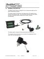
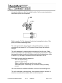
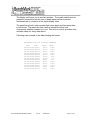
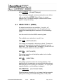
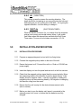
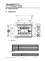
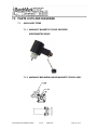
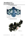
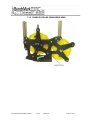
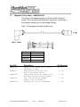
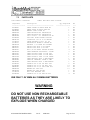
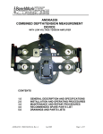
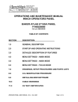
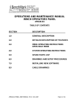
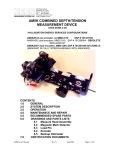
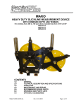
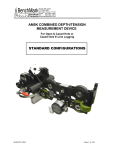
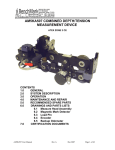
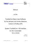
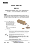
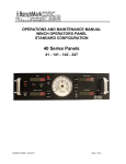
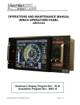
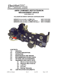
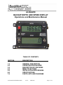
ALS6A200 BACKUP DEPTH AND SPEED DISPLAY Operations and Maintenance Manual TABLE OF CONTENTS SECTION DESCRIPTION 1.0 2.0 3.0 4.0 5.0 6.0 7.0 GENERAL DESCRIPTION OPERATING PROCEDURES DESCRIPTION OF FEATURES MENU SELECTIONS INSTALLATION PROCEDURES SPECIFICATIONS PARTS LISTS AND DIAGRAMS ALS6A200 LINE SPEED PANEL Rev E APR-2010 Page 1 of 25 1.0 GENERAL DESCRIPTION The Backup Depth System is designed to be an independent depth and line speed measurement indicator. The system consists of three items, the display panel, the magnetic pickup, and the interconnecting cable. An optional right angle drive with two outputs can also be provided to allow a Veedor Root counter to function simultaneously. The display panel is designed to be mounted inside the wireline unit. The magnetic pickup (shown below) is mounted to the speedometer drive output from the measuring head. ALS6A200 LINE SPEED PANEL Rev E APR-2010 Page 2 of 25 A magnetic pickup can also be installed inside of a Kerr measuring head so the external pickup is not required. Refer to section 7 of this document for photos showing the location of this pickup in different measuring heads. The unit is powered by three internal rechargeable batteries. It can be connected to an external AC or DC power source to keep the batteries charged. The unit is designed to operate without intervention from the user. When external power fails, the depth display is maintained by the batteries. When the magnetic pickup is inactive for the time set by the shutdown timer (refer to section 4.3), the depth is stored and the unit switches it self off. Front panel controls allow the operator to: Zero the depth reading Adjust the depth value Select a different settings using the menu button Switch the power off manually (for use when running on battery power) The unit cannot be switched off when connected to external power. The unit is switched on automatically, when external power is restored, or when the user selects the enable switch on the front panel ALS6A200 LINE SPEED PANEL Rev E APR-2010 Page 3 of 25 The display unit forces you to use two switches. The enable switch must be pressed in conjunction with the zero or depth adjust switch to prevent accidental loss or corruption of the depth display value. The panel has a built in data recorder that stores depth and line speed data in text format. The panel also has a built in internal clock that runs continuously whether powered up or not. This clock is used to provide a time and date stamp for every data record. Following is an example of the data showing the format. BenchMark Wireline Products ALS6A200 date time 24/04/10,00:44:51, 24/04/10,00:44:52, 24/04/10,00:44:53, 24/04/10,00:44:54, 24/04/10,00:44:55, 24/04/10,00:44:56, 24/04/10,00:44:57, 24/04/10,00:44:58, 24/04/10,00:44:59, 24/04/10,00:45:00, 24/04/10,00:45:01, 24/04/10,00:45:02, 24/04/10,00:45:03, ALS6A200 LINE SPEED PANEL Rev E depth speed 38.5,41.5,44.5,47.5,50.5,50.8,50.8,48.9, 45.9, 42.9, 39.9, 36.9, 33.9, APR-2010 179.6 179.8 179.8 179.8 179.8 97.8 0.0 12.1 179.8 179.8 179.8 179.8 179.8 Page 4 of 25 2.0 DESCRIPTION OF FEATURES 2.1 Enable Switch The ENABLE/OFF switch is a center-biased three position switch. It is used for several things: The up position powers the unit on, and the unit displays the stored value. It must be in the up position to zero or increase/decrease depth. If the switch is pressed down, the panel stores the displayed value in non-volatile memory and switches the unit off if not connected to external power. The unit cannot be switched off when connected to external power. Pressing the enable switch down will turn off the data recorder if it is not connected to external power. It is recommended that the data recorder be switched off before removing the memory card. To turn the data recorder on, the switch must be pressed up and the zero button pressed. The data recorder will remain on until it is turned off. When the panel is first powered up, the data recorder is powered on. 2.2 Menu Switch This button is used to change the internal settings of the panel. These settings include Measuring Head type, Line Size settings, Load Cell Angles, English/Metric units, Depth adjust (auto add/subtract), etc. Refer to section 4 for detailed description of these features. 2.3 Zero Switch The ZERO switch allows you to zero the display, it is a two position momentary switch. To activate this switch, you must hold the ENABLE switch up, then press this switch. ALS6A200 LINE SPEED PANEL Rev E APR-2010 Page 5 of 25 2.4 Increase / Decrease Switch The INCREASE/DECREASE switch is a center biased three position switch. Use the ENABLE switch to activate this switch: Hold both the enable and the increase/decrease switches up and the display value increases Hold the enable switch up, and the increase/decrease switch down and the display value decreases. The rate of increase (or decrease) is controlled by the length of time the INCREASE/DECREASE switch is held in position. For small adjustments, hold the ENABLE switch up and jog the INCREASE/DECREASE switch. 2.5 EXT PWR LED There is one LED on the front panel of the display unit. The LED is lit when the unit is connected to an external power source, either 240/120 vac or 12 vdc. If the LED is not lit, then the unit is operating off of battery power. ALS6A200 LINE SPEED PANEL Rev E APR-2010 Page 6 of 25 3.0 OPERATING PROCEDURES 3.1 Turn the unit on by pressing the enable switch up. If external power is applied, the unit will power on automatically. 3.2 Set the proper time and date for data recording. To change the time/date stamp, the ‘SL’ head type should be selected. To change the head type, press the menu button until ‘Hd’ is displayed. At this time press the +/- button until the desired head type is selected. After a setting is changed, continue pressing the menu button until the display reads ‘ACCEPt’. Press + then the menu button again to accept the setting. Once the ‘SL’ head type is selected, Refer to section 4.3.8 for more information on changing time/date settings. 3.3 If an SD/MMC Card is inserted, verify that data recording is on. To turn the data recorder on, the ENABLE switch must be held in the up position and the zero button pressed. Verify that the lower panel reads ‘rEC ON’. The data recorder will remain on until it is turned off. 3.4 Select the appropriate settings from the menu (see section 4.0) 3.5 Set the depth to the proper value by using the set depth switches or to 0 by pressing the zero switch. Note: the enable switch needs to be pressed in order to set depth. 3.6 The system is now ready to measure depth. 3.7 After each run in the hole, reset the zero value before entering the hole again. Note: the enable switch needs to be pressed in order to zero the depth. Some of the Industry standard wheel sizes in use are: CIRCUMFERENCE (FT) COUNTER TYPE 2 (MENU) 4 (MENU) 3.4034 4.2359 5.4009 BenchMark AM5K and AM3K BenchMark Shark or MegaMouth ASEP – MP13 ASEP – MP16 ASEP – MP20 ALS6A200 LINE SPEED PANEL Rev E APR-2010 Page 7 of 25 2 (MENU) 4 (MENU) 2 (MENU) 4 (MENU) .6667 .6562 2 (MENU) 1.6404 3.9424 1 1 2.5167 ASEP SMART HEAD HALLIBURTON TWO WHEEL (UNIVERSAL) OTIS 2’ WHEEL OTIS 4’ WHEEL LEE SLICKLINE COUNTER (FEET WHEEL) LEE SLICKLINE COUNTER (METRIC WHEEL) LEE BRAIDED LINE COUNTER (FEET WHEEL) LEE BRAIDED LINE COUNTER (METRIC WHEEL) SSR GEOLOG 3’ GEOLOG 2’ BAKER DWMD NOTE: MENU indicates that there is a menu selection for this counter. If there is no menu selection, use wheel size OTHER. 4.0 MENU SELECTIONS The internal settings of the panel can be set by pressing the menu button. To change a setting, press and release the menu button until the desired setting is displayed. Use the +/- switch to change the setting. After a setting is changed, continue pressing the menu button until you pass the last setting. At this time you will be asked if you want to ACCEPT the setting changes. To accept the changes press +, YES will appear, then press the MENU button. If you press – or wait for four seconds, the changes will be ignored. If you wait for four seconds between switch presses, the panel will time out and go back to displaying depth. Following is a summary of the process. PRESS MENU CHANGE DISPLAYED PARAMTER BY PRESSING +/- SWITCH PRESS MENU BUTTON AGAIN ALS6A200 LINE SPEED PANEL Rev E APR-2010 Page 8 of 25 CHANGE DISPLAYED PARAMTER BY PRESSING +/- SWITCH CONTINUE UNTIL ACCEpT IS DISPLAYED. PRESS + TO SAVE THE SETTINGS PRESS MENU BUTTON AGAIN WHEN YES IS DISPLAYED. Note: If + is not entered or the menu button is not depressed when YES is displayed, any changes made to the parameters will not be saved. There are four different menus, one for each of the different type of measuring systems. 3 – BenchMark AM3K Cased Hole Measuring head 5 – BenchMark AM5K Open Hole / Cased Hole Measuring head SL – BenchMark dual 16” (Shark or MegaMouth) or 20” (MAKO) Wheel Slickline Measuring head OtH – Other wheel size To change the head type, press the menu button until Hd is displayed. At this time press the +/- button until the desired head type is selected. After a setting is changed, continue pressing the menu button until you pass the last setting. Press the menu button again until ACCEPt appears. Press the + switch and YES will appear, then press MENU once more to save the setting. Each head type has a different menu. Following are the available settings for each. 4.1 HEAD TYPE 3 (AM3K) This mode is for a BenchMark AM3K cased hole measuring head. The available menu selections in AM3K mode are: 4.1.1 LS ALS6A200 LINE SPEED PANEL (LINE SIZE) Rev E APR-2010 Page 9 of 25 This selection is use to choose the size of the cable you will be using. This setting will adjust the wheel size to account for the size of cable. The available sizes are: 3/8, 5/16, 9/32, 1/4, 7/32 The wheel size settings for each are: 3/16” cable – 2.014 ft. 7/32" cable - 2.017 ft. 1/4” cable – 2.020 ft. 9/32" cable – 2023 ft. 5/16" cable - 2.026 ft. 3/8" cable – 2.031 ft. 4.1.2 AdJ (DEPTH ADJUST) This setting is comparable to shimming a wheel. The amount selected will automatically be added or subtracted from the depth input. The values are feet / thousand. If you set it at 1.00 Ft then 1ft will be added over the next 1000ft. 4.1.3 Un (DEPTH UNITS) This setting is used to set the display readout units to either ‘Ft’ for FEET or ‘nt’ for METERS. 4.1.4 dir (DIRECTION) This setting is used to reverse the counting direction. The depth should be increasing as you are going into the hole and decreasing as you are coming out of the hole. If it is going the opposite direction, use this setting to change it. 4.1.5 SHUT dn (SHUT DOWN TIMER) When the device is inactive (i.e. no change from the magnetic pickup) and running on internal battery power, it will power itself down when the elapsed time exceeds this Shut Down Timer value. For more on shut down see section: 4.3.5.4. ALS6A200 LINE SPEED PANEL Rev E APR-2010 Page 10 of 25 4.1.6 ACCEPt (Accept Changes) After a setting is changed, continue pressing the menu button until you get to the ‘ACCEPt’ Menu. Press + to accept changes, and – to discard changes. Press the menu button again to accept the setting. 4.2 HEAD TYPE 5 (AM5K) No wheel size selections are available. It is set for a 2’ circumference measuring wheel. Use this setting for any straight-line measuring device that uses a 2 foot measuring wheel. Use this mode for the Kerr AM5K measuring head. The available menu selections in mode 5 are: 4.2.1 AdJ (DEPTH ADJUST) This setting is comparable to shimming a wheel. The amount selected will automatically be added or subtracted from the depth input. The values are feet / thousand. If you set it at 1.00 Ft then 1ft will be added over the next 1000ft. 4.2.2 Un (DEPTH UNITS) This setting is used to set the display readout units to either FEET or METERS. 4.2.3 dir (DIRECTION) This setting is used to reverse the counting direction. The depth should be increasing as you are going into the hole and decreasing as you are coming out of the hole. If it is going the opposite direction, use this setting to change it. 4.2.4 SHUT dn (SHUT DOWN TIMER) When the device is inactive (i.e. no change from the magnetic pickup) and running on internal battery power, it will power ALS6A200 LINE SPEED PANEL Rev E APR-2010 Page 11 of 25 itself down when the elapsed time exceeds this Shut Down Timer value. For more on shut down see section: 4.3.5.4. 4.2.5 ACCEPt (Accept Changes) After a setting is changed, continue pressing the menu button until you get to the ‘ACCEPt’ Menu. Press + to accept changes, and – to discard changes. Press the menu button again to accept the setting. 4.3 HEAD TYPE SL (SLICKLINE) This mode is to be used for slickline measuring systems. There are several different selections available which make if flexible enough to work with virtually any type of slickline measuring head. This mode must be selected to be able to set the clock. Selections are available for different wheel sizes, line sizes, and groove sizes. Use this mode for a BenchMark SHARK or MegaMouth system using a 4’ counter wheel. The available menu selections in SL mode are: 4.3.1 LS (LINE SIZE) Select the size of the wireline you will be using. This setting will adjust the wheel size to account for this size of cable. The available sizes are: .082 .092 .108 .125 .140 .160 ALS6A200 LINE SPEED PANEL Rev E APR-2010 Page 12 of 25 3/16 7/32 1/4 5/16 OtH (OTHER) 4.3.2 AdJ (DEPTH ADJUST) This setting is comparable to shimming a wheel. The amount selected will automatically be added or subtracted from the depth input. The values are feet / thousand. If you set it at 1.00 Ft then 1ft will be added over the next 1000ft. 4.3.3 Un (DEPTH UNITS) This setting is used to set the display readout units to either FEET or METERS. 4.3.4 dir (DIRECTION) This setting is used to reverse the counting direction. The depth should be increasing as you are going into the hole and decreasing as you are coming out of the hole. If it is going the opposite direction, use this setting to change it. 4.3.5 SEtUP If you press + when at setup, the following options become available. 4.3.5.1 C (WHEEL CIRCUMFERNCE) The following five options are available. 2 ft 4 ft .625 meter 1.25 meter MAKO You can choose one of the four standard wheel sizes or select OTHER to choose the circumference of the measuring wheel. ALS6A200 LINE SPEED PANEL Rev E APR-2010 Page 13 of 25 The OTHER option allows you to input a wheel circumference ranging from ½ foot to 10 foot in circumference. Refer to Section 2.0 operating procedures for a list of industry standard measuring heads and the settings to use with these heads. (note that display will be in meters if meters is selected for units) 4.3.5.2 Gr (GROOVE SIZE) This setting allows you to choose the groove size of the measuring wheel (in inches). This setting can range from 0 (flat wheel) to a 1” groove. The available sizes are: .082 .092 .108 .125 .140 .160 3/16 7/32 1/4 5/16 OtH (OTHER) If MAKO is selected the only available groove size is 5/16” The MAKO wheel is grooved to accept up to 5/16” wireline. If OTHER is selected you can enter any value from 0 (flat wheel) to a 1” groove. 4.3.5.3 SEt CL (SET CLOCK) This feature provides a means to set the internal clock. ALS6A200 LINE SPEED PANEL Rev E APR-2010 Page 14 of 25 Use the following procedure to set the clock. When SEt CL appears, press + min (MINUTES) will then appear. Press the + or – switch until the correct minute (00-59) is selected then press MENU. HOUr (HOUR) will next appear. Press the + or – switch unit the correct hour is selected then press MENU. Note: The hours are set in 24 Hour format (01 – 24). dAtE (DATE) will next appear. Press the + or – switch unit the correct day of the month (1-31) is selected then press MENU. mOntH (MONTH) will next appear. Press the + or – switch unit the correct month (0-12) is selected then press MENU. yEAr (YEAR) will next appear. Press the + or – switch unit the correct year (0-99) is selected then press MENU. StArt (START) will next appear. The time and date entered will now appear but the clock will not start until + is pressed. This feature can be used to syncronize the clock with an external clock. 4.3.5.4 SHUt dn (SHUT DOWN TIMER) When the device is inactive (i.e. no change from the magnetic pickup) and running on internal battery power, it will power itself down when the elapsed time exceeds this Shut Down Timer value. The shutdown timer can be set in increments of 1 hour from 1 to 9. The default value is 1 hour. If 0 is selected, the shutdown timer will be ignored and the device will continue to remain on. ALS6A200 LINE SPEED PANEL Rev E APR-2010 Page 15 of 25 The shutdown timer is restarted whenever a depth change is detected from the magnetic pickup and the device is not connected to external power. If the device is connected to external power, the shutdown timer is not used and the device will remain powered up even if no change is detected from the magnetic pickup. When the device switches itself off it stores the displayed value in non-volatile memory. When turned back on this value is restored to the display. 4.4 HEAD TYPE OtH (OTHER) This menu is to be used if you have a measuring device with a different wheel circumference than the standard Kerr measuring devices. No line size selections are available The available menu selections in the OTHER menu are: 4.4.1 Cr (WHEEL CIRCUMFERENCE) This setting represents the circumference of the measuring wheel. Use the +/- switch to adjust the setting to match the circumference of the measuring wheel you are using. 4.4.2 AdJ (DEPTH ADJUST) This setting is comparable to shimming a wheel. The amount selected will automatically be added or subtracted from the depth input. The values are feet / thousand. If you set it at 1.00 Ft then 1ft will be added over the next 1000ft. 4.4.3 Un (DEPTH UNITS) This setting is used to set the display readout units to either FEET or METERS. ALS6A200 LINE SPEED PANEL Rev E APR-2010 Page 16 of 25 4.4.4 dir (DIRECTION) This setting is used to reverse the counting direction. The depth should be increasing as you are going into the hole and decreasing as you are coming out of the hole. If it is going the opposite direction, use this setting to change it. 4.4.5 SHUT dn (SHUT DOWN TIMER) When the device is inactive (i.e. no change from the magnetic pickup) and running on internal battery power, it will power itself down when the elapsed time exceeds this Shut Down Timer value. For more on shut down see section: 4.3.5.4. 5.0 INSTALLATION AND MOUNTING 5.1 INSTALLATION PROCEDURE 5.1.1 Prepare an appropriate panel cut-out with four fixing holes. 5.1.2 Connect the magnetic pickup cable to the rear of the unit. 5.1.3 Ensure that power is off. Connect the unit to a 12vdc or 120/240 vac power supply. 5.1.4 Insert the display unit into the panel and secure it at the four corners. 5.1.5 Check that the magnetic pickup signal has the correct polarity. Move the measuring wheel in the direction of positive depth (down). If the display shows a negative value, it can be corrected by rotating the magnetic pickup on the measuring head by 180 degrees or changing the direction using from the menu. 5.1.6 Ensure that the unit is setup for the desired measurement units (feet or meters). 5.1.7 Before you start to use the display unit, leave it connected to the external power for 4 hours to ensure that the batteries are fully charged. ALS6A200 LINE SPEED PANEL Rev E APR-2010 Page 17 of 25 6.0 SPECIFICATIONS 6.1 DIMENSIONS 6.1 Mechanical Material Weight IP Rating Temperature Humidity 6.3 Aluminium, anodized 1.5 lbs (.68 kg) 40 0 to + 50 Centigrade 10% - 80% RH non-condensing. Electrical Input power Voltage 100 - 240 VAC or 12 – 24 VDC Input power frequency 50 - 60 Hz, DC ALS6A200 LINE SPEED PANEL Rev E APR-2010 Page 18 of 25 Input power current 6.4 0.4 A Batteries Battery Voltage Lifetime 2100 mAh 1.2 V NIMH Approx. 5 years (depending on usage) The batteries are trickle charged when external power is connected to the unit. The batteries are fully charged after 3 hours. The batteries discharge if the unit is left unpowered for a few weeks. 6.5 Power consumption and operating time Operating Magnetic pickup assembly 6.6 10 mA (typical) 20 mA (remainder powers the display) AC Power Input Live Neutral Earth Brown Blue Green/Yellow White Black Green Power is fused inside the display unit case with a 250 mA fuse 6.7 DC Power-input Live Neutral Earth Pin 1 Pin 2 Pin 3 DC connector spec: AM5KP063 -CONN KPT06E8-33S 3 SOCKET ALS6A200 LINE SPEED PANEL Rev E APR-2010 Page 19 of 25 6.8 Depth measurement Quadrature counts/revolution Measurement resolution Display resolution 6.9 0.1573 ft 0.1 ft Line Speed Minimum Line Speed Maximum Line Speed 6.10 16 0.048 m 0.1 m 0 ft/min 1200 ft/min Power management Power time-out with idle magnetic pickup 60 min The battery voltage and charge current can be displayed by pressing enable and menu at the same time. The voltage will be displayed as: E 4180 4180 would be a battery voltage of 4.18 volts. When the battery reaches 4.8v the charge will stop. The charge current will be displayed as: A 310 310 would be a battery charge current of 310 ma. The display will cycle between the voltage and current display as long as the buttons are being depressed. The charge current is limited to between 250 ma and 350 ma. ALS6A200 LINE SPEED PANEL Rev E APR-2010 Page 20 of 25 7.0 PARTS LISTS AND DIAGRAMS 7.1 AUXILLIARY ITEMS 7.1.1 AMSLA057 MAGNETIC PICKUP ENCODER SPEEDOMETER DRIVE 7.1.2 AM5KA055 MEASURING HEAD MAGNETIC PICKUP ASSY ALS6A200 LINE SPEED PANEL Rev E APR-2010 Page 21 of 25 7.1.3 AM3K MEASURING HEAD 7.1.4 AM5K MEASURING HEAD ALS6A200 LINE SPEED PANEL Rev E APR-2010 Page 22 of 25 7.1.5 SHARK SLICKLINE MEASURING HEAD ALS6A200 LINE SPEED PANEL Rev E APR-2010 Page 23 of 25 7.2 Magnetic Pickup Cable – AM5KA024-XX The wiring to the magnetic pickup is via a 6 pin MIL-C chassis socket. This is mounted with terminal A uppermost. The wiring to the magnetic pickup is pin-for-pin straight through. Note: XX designates the cable length in feet Function Vsensor Channel A Channel B Ground Kerr P/N AMS4P222 AM5KP057 AM5KP058 AM5KP059 AM5KA034 Pin Number A E C D Description CABLE 20/4C ALPHA 25154 BLACK SHIELDED 0.28OD CONN KPT06F10-6P STR PLUG MS3116 W/STRAIN RELIEF CONN KPT08F10-6S RT ANGLE PLUG W/STRAIN RELIEF OR EQUIVALENT DUST CAP KPT8010C CANNON SHELL SIZE 10 OR EQUIV BUSHING #9779-513-4 AMPHENOL ALS6A200 LINE SPEED PANEL Rev E APR-2010 Qty Required XX FT 1 EA 1 EA 2 EA 2 EA Page 24 of 25 7.3 PARTS LISTS Item Number: ALS6A200 Component --------------ALS6M021 ALS6M022 AMS4P895 AM5KP056 AMS4P257 AMS4P569 ALS6A020 AMS4P756 C276P155 C276P151 AMS4P618 AMS4P021 AMS7P017 AMS4P631 AMS4P659 AMS7P021 AMS7P023 AMS7P024 AMS4P661 AMS4P662 AMS4P663 ALS6P032 ALS6P085 AMS8P091 AMS8P036 AMS4P626 C276P158 ALS6P026 PANEL AMS BATT BKUP DISPLAY Description -----------------------------PANEL FRONT 2X BKUP REAR MT PANEL REAR 2X BKUP REAR MT MEMORY CARD 512MB SD CONN KPT02E10-6S RECEPTACLE CONN KPT02E8-33P RECEPTACLE LCD 6 DIGIT .71" REFLECTIVE TN PCB ASSY DEPTH SPEED DISPLAY LIGHTPIPE 5/16 X 0.52 SEALED CABLE BELDEN 177431 10' AC RECEPTACLE 6ESRM-3 CORCOM AC BATTERY 1.2V NIMH AA 2100MAH SWITCH CAP ALCO C-22 BLACK SWITCH CAP ALCO C-22 RED NUT 1/4-40 DRESS BRIGHT NICKEL CONN TERMINAL RECPTACLE .25TAB CONN 102398-4 AMP 12 POS PCB CONN 102536-4 AMP 12 POS BACK CONN 102681-1 AMP 12 POS FRONT CONN HOUSING 3POS 2.5MM SHROUD CONN FE TERMINAL CRIMP 2.5MM CONN HOUSING 2POS 2.5MM SHROUD SCREW 4-40 X 3/8 FH PHIL SST SCREW 4-40 X 1/4 FH PHIL SST SCREW 4-40 X 1/4 PHIL PAN SST WASHER #4 LOCK SST WASHER #4 FLAT NYLON NUT 4-40 MACHINE SST SCREW 6-32 X 7/8 BTN HD SST Qty Required ---------------1 1 1 1 1 0 1 1 1 1 3 1 1 4 3 1 1 1 1 4 1 2 14 12 13 1 1 4 UM --EA EA EA EA EA EA EA EA EA EA EA EA EA EA EA EA EA EA EA EA EA EA EA EA EA EA EA EA USE ONLY 1.2V NIMH AA 2100MAH BATTERIES WARNING DO NOT USE NON RECHARGEABLE BATTERIES AS THEY ARE LIKELY TO EXPLODE WHEN CHARGED ALS6A200 LINE SPEED PANEL Rev E APR-2010 Page 25 of 25