1
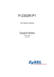
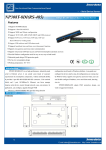
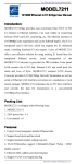
NP304 Series
4port RS
/485/422 to Ethernet Serial Server
4-port
RS--232
232/485/422
User manual
Shenzhen 3onedata Technology Co.,Ltd
Tel: +86-755-26702688
Fax: +86-755-26703485
www.3onedata.com
NP304 series User Manual
Contents
1. Introduction
Introduction.......................................................................................................................... 3
2. Packing List
List.......................................................................................................................... 3
3. Features
Features................................................................................................................................. 3
4. Specifications
Specifications...................................................................................................................... 3
5. Panel Layout
Layout........................................................................................................................ 5
5.1 Front panel
panel....................................................................................................................................... 5
5.2 Rear panel (RS-232/485/422 Port)
Port)..............................................................................................6
6. Dimension
Dimension............................................................................................................................. 6
7. Software installation and setting
setting.................................................................................... 7
7.1 Set the IP address of the device
device................................................................................................ 7
7.2 Create the Virtual COM port on the PC
PC.................................................................................... 9
8. Application
Application.......................................................................................................................... 10
9. FAQ...................................................................................................................................... 11
Page 2 of 11
NP304 series User Manual
1. Introduction
NP304 series can conveniently connect up to 4 serial devices to an Ethernet, allowing you to
network your existing serial devices with only basic configuration. With NP304 series, you
can both centralize the management of your serial devices, and distribute management hosts
over the network.
NP304 series can be used to connect different devices for remote management, each serial
port operates independently to provide maximum versatility, each port can be operate in
Driver, TCP Server, and TCP Client mode independently.
2. Packing List
NP304 series are shipped with following items.
1. NP304 series server×1
2. User manual ×1
3. Quick Installation Guide ×1
4. Straight network cable ×1
5. 5VDC power adapter ×1
6. Software CD-ROM×1
7. Product Warranty booklet×1
Optional accessories:
DIN-Rail Mounting Kit (35mm) ×1
3. Features
1. Adopt 32 bit ARM processor, 125 DMIPS manage ability
2. 4 serial ports, with support for RS-232/RS-485/RS-422
3. Support 10/100M Ethernet
4. Support 300bps-460.8Kbps
5. Support TCP, UDP, ARP, ICMP, HTTP, TELNET and DHCP protocol
6. Support across gateway, router communication
7. Support standard TCP/IP SOCKET
8. Support Virtual serial driver access and auto connect after the network disconnect
9. Choice of configuration methods: Windows, TELNET and WEB
10. Support DIN-Rail or wall mounting installation
4. Specifications
Ethernet
Number of ports:1
Standard:10/100Base-T(X)
Speed:10/100M auto-sensing
Working mode: half /full duplex
Working: TCP Server, TCP Client, UDP and Real COM driver
Page 3 of 11
NP304 series User Manual
Memory: Most 32Kbyte
Transmission: 100m
Electromagnetism isolate: 1KV
Connector: RJ45
Serial
Standard: RS-232/RS-485/RS-422
Number of ports: 4
Signals: RS-232:DCD,RXD,TXD,DTR,GND,DSR,RTS,CTS
RS-485:Data+,Data-,GND
RS-422:TXD+,TXD-,RXD+,RXD-,GND
Parity: None, Even, Odd, Space, Mark
Data bits: 5bit, 6bit, 7bit, 8bit
Stop bits: 1, 1.5, 2
Baud rate: 300bps ~ 460.8Kbps
Flow control: RTS/CTS or XON/XOFF
Direction control: RS485 side adopt ADDC technology, auto text and control data transfer
direction
Loading: RS-485/422 side support 32 nodes (customize 128 nodes) loopback
Transmission: RS-485/422 side 1200M,
RS-232 port 15M
Interface protection:1500W surge protection,
15KV ESD protection
Software
Network protocols: Support TCP, UDP, ARP, ICMP, HTTP, TELNET and DHCP
Driver support: Windows Real COM driver
(Windows NT/2000, Windows XP/2003)
Configuration options: Windows, TELNET and WEB
Power
Power input: 5VDC
Consumption: <1W
Environment
Working temperature:-20℃~60℃(-4F~140F)
Storage temperature:-25℃~85℃(-13F~185F)
Humidity: Relative humidity 5% to 95%
Appearance
Color: Black
L×W×H: 160.0mm×91.2mm×30.4mm
Material: Iron (Shell)
Weight: 240g
Warranty: 5 years
Approvals: FCC, CE, RoHS approvals
Page 4 of 11
NP304 series User Manual
5. Panel Layout
5.11 Front panel
5.
DC-IN: 5VDC power supply input
10/100M Ethernet: 10/100Base-T(X) Ethernet input and output
POWER:: Bright all along when connect power supply
POWER
LINK: Bright all along when connected
10/100M: ON is 100M, OFF is 10M
/100
Base-T
(X) Ethernet port
10/100
10
/100Base-T
Base-T(X)
port::
The 10/100BaseT(X) ports located on NP304 series front panel. The pin of RJ45 port
display as below. Connect by UTP or STP. The connect distance is no more than 100m.
100Mbps is used 100Ωof UTP , 10Mbps is used 100Ωof UTP 3,4,5. RJ45 port support automatic MDI/MDI-X operation. can connect the PC, Server,
Converter and HUB by straight–though cable wiring . Pin 1, 2, 3, 6 Corresponding connection
in MDI. 1→3, 2→6, 3→1, 6→2 are used as cross wiring in the MDI-X port of Converter and
HUB. 10Base-T are used in MDI/MDI-X, the define of Pin in the table as below.
pin
1
8
MDI
signal
1
TX+
2
TX3
RX+
6
RX4, 5, 7, 8 —
MDI-X
signal
RX+
RXTX+
TX—
±” transmit data
±, “RX
±” receive data
±, “—”
not use
Note:““TX
Note
TX±”
data±
RX±”
data±
“—”not
MDI(Straight-through cable):
R J4 5
8
1
TX +
3
3
TX-
6
6
RX-
RX+
1
1
TX+
RX-
2
2
TX-
Page 5 of 11
RX+
NP304 series User Manual
MDI-X (Cross-over cable):
R J4 5
8
1
(R X + ) T X +
3
1
(R X -) T X -
6
2
R X - (T X -)
(T X + ) R X +
1
3
T X + (R X + )
(T X -) R X -
2
6
T X - (R X -)
R X + (T X + )
5.22 Rear panel (RS-232/485/422 Port)
5.
NP304
NP304
NP3044-2M
NP30
NP30
NP3044-4M
4-port RS232 to Ethernet
(2-port RS232+2-port RS485/422) to Ethernet
4-port RS485/422 to Ethernet
RS-485/422 (RJ45
RJ45))
1 TXD+/Data+
3 RXD+
2 TXD-/Data6
4 RXD-
GND
1
RS-232 (RJ45
RJ45))
1 TXD 2 RXD
5 DSR 6 GND
3 RTS
7 DTR
4 CTS
8 DCD
6. Dimension
Page 6 of 11
8
NP304 series User Manual
7. Software installation and setting
7.1 Set the IP address of the device
The IP address of the device and the PC must in the same subnet (the default IP of the device is in the subnet
of 192.168.1.233). First, must make the IP address of the device in the same subnet network(192.168.1.X)
of PC.
If they are not in the same subnet network or the IP address have been used by another device,
Use Telnet change the IP address of the device.
Start
all programs
Running
I. “Start
Start” → “all
programs” → “Running
Running”
Telnet: 192.168.1.233
OK
II. Input default IP address of the device “Telnet:
192.168.1.233”. Click “OK
OK”, setting the IP
ESC
of device by telnet. Choose the menu by “↑, ↓, ←, →” of the keyboard and quit by “ESC
ESC”
key.
OK
III. Knock “OK
OK”. Set the IP of device by telnet. Choose the menu by “↑, ↓, ←, → “of the
ESC
Server
Enter
keyboard and quit by “ESC
ESC” key. Choose the “Server
Server” menu and Knock “Enter
Enter” key,
Change the IP of the device.
Esc
IV. Change the IP (the changed IP must be in the subnet of the PC). then Knock “Esc
Esc” key, quit the network
Page 7 of 11
NP304 series User Manual
setting.
COMMON
Enter
V. Choose “COMMON
COMMON”, knock “Enter
Enter”,
Save Configuration
VI. Choose “Save
Configuration”, knock “Enter”, due to save the setting.
Page 8 of 11
NP304 series User Manual
7.2 Create the Virtual COM port on the PC
setup_nt_2K.exe
com port over tcp/ip.exe
I. Setup the “setup_nt_2K.exe
setup_nt_2K.exe” software, you will find the “com
tcp/ip.exe”
application in the control panel of windows OS.
COM port over tcp/ip.exe
II. Double knock “COM
tcp/ip.exe” application and create virtual the serial port to
communicate with the device on the PC.
Map
III. Choose the name of the virtual serial port and Knock “Map
Map” button. Set the parameter of
the virtual serial port.
Page 9 of 11
NP304 series User Manual
1. Input the IP address of the device
2. Input the NO. of the port of the device(input 1~8)
3. Input 300
4. Default the parameter
OK
Save
IV. Knock “OK
OK”, Knock “Save
Save”. Then you can use the created the COM5.
V. The virtual serial port COM5 can communicate with the terminal on the NO.1 port of the
device.
8.
Application
NP304 series can be used to connect different devices for remote management, each serial port
operates independently to provide maximum versatility, each port can be operate in Driver,
TCP Server, and TCP Client mode independently.
Pay attention to the questions as below
below:
(1) Make sure the power supply input is 5VDC;
(2) Use the cross-over cable if the devices connect to the PC.
(3) Use the straight-through cable if the devices connect to the HUB.
Note: Cable (blue) with the product is a straight-through cable.
Page 10 of 11
NP304 series User Manual
9. FAQ
1. Power adapter is incorrect and connection is incorrect
Solution: Please make sure that the power supply is 5VDC
2. Vircom connection is failure, LED indicator is OFF
Solution: at first, delete the virtual COM port that do not connect successful. Create a
new virtual COM port and connect it, detect LED indicator is ON of OFF
3. Parameter setting is incorrect.
Solution: Enter into the management IP address of device through IE browser, check
space
“Parity
Parity” , If it is Mark/space, Parity Check must set “space
space”, then you can adjust Force
Packet Transmit Time and Force Packet Transmit Length
Length.
Note: If you also have some problem about the NP301B, please contact your customer service
Note
representative for support.
Page 11 of 11