1
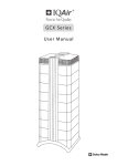
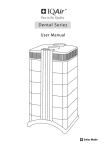
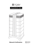
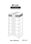
H e a l t h Pro® 150
Us e r M a n u a l
Swiss Made
105.10.40.40_131220_IN_MA_HP150_EN(CN)
Important Safety Instructions
About This User’s Manual
Congratulations on your purchase of this high-performance air cleaning system made by IQAir AG of Switzerland.
Please study this user manual carefully to familiarize yourself with the special features and functions of your system
and keep it in a safe place for future reference.
Read these instructions before using the appliance:
• Do not use this appliance as sole protection against harmful pollutants.
• Do not immerse the appliance in water or other liquids.
• Always disconnect the power from your air cleaner by unplugging the power cable before adding or removing
parts and before cleaning.
• Do not operate this appliance if it has a damaged cord or plug, if the motor fan fails to rotate, if it is not working
properly, if it has been dropped or damaged, or immersed in water.
• If the mains cord of this appliance should become damaged, it may be replaced with a similar cord set, as is
commonly used for computers and similar appliances.
• Only use this appliance for its intended purpose of air cleaning in non-industrial environments.
• Do not use this appliance in areas with very high concentrations of dusts or powder to prevent the danger of dust
explosions.
•
•
•
•
•
•
•
•
•
Do not use this appliance in explosive areas.
Only use filters and accessories recommended by the manufacturer.
Do not use outdoors.
Do not obstruct the air inlet and air outlet of the air cleaner.
Do not place the appliance on a soft surface such as a bed or other soft furnishings.
Only use this appliance in an upright position.
Do not place next to a humidifier.
Keep the power cord away from heated surfaces.
Save these instructions for future reference.
This appliance is not intended for use by persons (including children) with reduced physical, sensory or mental
capabilities, or lack of experience and knowledge, unless they have been given supervision or instruction concerning
the use of the appliance by a person responsible for their safety.
Children should be supervised to ensure that they do not play with the appliance.
IQAir AG, Switzerland reserves the right to change specifications contained in this document at any time and without prior notice.
© 1998 – 2014 IQAir AG, Switzerland. All rights reserved. HealthPro® and HyperHEPA® are the registered trademarks of the IQAir AG, Switzerland. V5-Cell™, PreMax™
and EvenFlow™ are trademarks of the IQAir AG, Switzerland. This air cleaning system and its filters are protected under U.S. patents 6 001 145 and
6 159 260. Other U.S., European and Asian patents pending.
3
Table of Contents
Page
Important Safety Instructions
3
Chapter 1 – Air Cleaning Systems and Indoor Air Quality
1. 1
Improving Indoor Air Quality
5
5
Chapter 2 – Setting Up
2. 1
Unpacking
2. 2
Fitting Your Air Purifier with Casters
2. 3
Choosing a Suitable Location
2. 4
Connecting to Power
6
6
7
8
8
Chapter 3 – The System’s Components
3. 1
Description of Housing Components
3. 2
Description of Removable Components
3. 3
How the System Works
9
9
10
10
Chapter 4 – Using the Control Panel
4. 1
Description of Control Panel
4. 1. 1
Description of Control Panel Keys
4. 2
Control Panel Locking Function
4. 3
Fan Speed and Air Delivery
4. 3. 1
Regulating Fan Speed
4. 3. 2
Air Exchange Rates in Differently Sized Rooms
4. 4
Using the Menu Functions
4. 4. 1
Menu Overview
4. 4. 2
Filter Life Monitor
4. 4. 3
Setting the Daily Timer
4. 4. 4
Setting the Weekly Timer
4. 4. 5
Timer ON/OFF Fan Speed Selection
4. 4. 6
Timer Information in the Control Panel
4. 4. 7
Time & Day Setting
4. 4. 8
Filter Life Reset
4. 4. 9
Changing Airflow Units
4. 4. 10 Language Setting
4. 4. 11 Filter Load Index Setting
4. 4. 11.1 Determining the Filter Load Index
4. 4. 11.2 Modifying the Filter Load Index
11
11
11
12
12
12
13
13
13
14
15
16
16
17
17
18
18
18
19
19
20
Chapter 5 – Using the Remote Control
5. 1
Remote Control Functions
5. 2
Getting the Best Transmission Results
5. 3
Placing Batteries in the Remote Control
21
21
21
22
Chapter 6 – Replacing Filters
6. 1
Location of the Filters
6. 2
Ordering Replacement Filters
6. 3
Opening and Closing the Housing
6. 3. 1
Troubleshooting when Closing the Housing
6. 4
Replacing the PreMaxTM Filter (Filter 1)
6. 5
Replacing the HyperHEPA® Filter (Filter 2)
6. 6
Discarding Used Filters
22
22
22
23
23
23
25
25
Chapter 7 – Maintenance
7. 1
Cleaning the Housing
7. 2
Maintenance-Free Fan
25
25
25
Chapter 8 – Accessories (Optional)
26
4
Chapter 1 – Improving Indoor Air Quality
Chapter 1 – Air Cleaning Systems and Indoor Air Quality
1.1 Improving Indoor Air Quality
Air cleaning can play an important role when it comes to improving indoor air quality. However, it should be noted
that air cleaning should be used in conjunction with pollution source control and ventilation, wherever possible.
Strategy to improve indoor air quality
To tackle any indoor air quality problem, keep the following three-step strategy in mind:
1. Eliminate or reduce the air pollution source as much as possible. Source control is by far the most effective way to
improve indoor air quality, since it sets out to deal with air pollution at the point of origin.
2. Ensure that sufficient fresh air is entering the room from outside. Air cleaners are not a substitution for sufficient
ventilation. They are not able to reverse the conversion of oxygen (O2) into carbon dioxide (CO2), caused by
breathing and combustion processes.
3. Ensure the system can clean enough air to cope with your room size. The actual hourly air volume cleaned by the
system should be at least double the air volume of your room. If the rate at which pollutants enter the room air is
high or the indoor air quality requirements are stringent, the hourly air delivery of the system needs to exceed the
room air volume several times. To achieve that level of air turnover, it may be necessary to employ more than one
system.
Air Cleaning Results
Although air cleaners may be advertised and sold to be suitable for use in specific indoor environments and to deal
with specific indoor air quality problems, the manufacturer and distributors make no claim as to the specific air
cleaning results that are achieved under the user’s individual operating conditions. The air quality improvements
that can be realized with this system (as with any air cleaner) in indoor environments depends to a significant degree
on circumstantial factors, which are out of the control of the manufacturer or distributors. Important factors which
will influence the air quality improvements that can be achieved in an indoor environment with an air cleaner
include:
• Type of air pollutants present
• Intensity of the pollutant source(s)
• Pollutant concentration
• Size of the indoor environment (room size)
• Operating speed of the unit
• Number of air cleaners placed in the indoor environment
• Saturation state of the filters in the air cleaner
Consult a qualified specialist to determine an effective and comprehensive indoor air quality strategy.
5
Chapter 2 – Setting Up
Chapter 2 – Setting Up
2.1 Unpacking
To unpack the system, open the top of the box and remove the square styrofoam pad which contains all accessories
and product literature. Lay the box on its side, hold the system by the handle and pull it out of the box. Remove the
plastic bag and foam belt. Keep the packaging for future transport and service needs.
Advanced Air Cleaning System
Power cord
(plug types vary)
H e a l t h Pro® 150
Certificate of Performance
Us e r M a n u a l
Model:
HealthPro 150
Shell No.:
Testing carried out by:
1 A E E A 0 0 0 0
Signed: _________________
Test Voltage/Frequency:
Serial No.:
Testing & QC Dept.
230V, 50Hz
This certifies that the aforementioned air cleaning system has been tested prior to packaging
at the production facility in Switzerland. This particular system has been found to
be in compliance with the model’s published specifications for air delivery and particle
filtration efficiency. This system has also passed the particle leakage test.
I. Air Delivery Rate
Published Air Delivery
The aforementioned system
has been tested for its air
delivery at all fan speed
settings. Due to component
tolerances, a divergence of
10% +10 m3/h is deemed
acceptable.
Note:
The air delivery rate refers
to the system’s initial air
delivery, which will decrease
as filters load up with dust
particles.
Speed 1:
m3/h
Actual Air Delivery
Speed 1:
m3/h
80
m3/h
Speed 2:
m3/h
140
m3/h
Speed 3:
m3/h
Speed 4:
190
m3/h
Speed 4:
m3/h
Speed 5:
240
m3/h
Speed 5:
m3/h
Speed 6:
350
m3/h
Speed 6:
m3/h
Measuring instrument: Alnor LoFlo Balometer
Instrument accuracy: ± (3% + 8 m3/h)
Swiss Made
40
Speed 2:
Speed 3:
m3/h = cubic meters per hour
1 m3/h = 0,59 cfm
105.60.10.20_101109_Cert_E_HP150
105.10.40.40_131220_IN_MA_HP150_EN(CN)
Remote control
including battery
6
Set of casters
User manual
Certificate of
Performance
Warranty Card and
Technical Specifications
Chapter 2 – Setting Up
2.2 Fitting Your Air Purifier with Casters
Attaching the supplied casters is optional. They make it
easy to move the air purifier between rooms.
Attention: Please be careful and roll the unit gently when
moving it over thresholds or other obstacles to avoid
breakage.
The Mobility Caster kit consists of:
1. mounting rail ( x 2)
2. casters ( x 4)
For installation simply follow the below instructions:
1
2
Turn the device upside down on a soft and clean
surface.
Place the mounting rail on the purifier’s base so that
the holes line up with the black connector pins on the
base. The cut-ins should face the center of the unit.
4
3
Place the caster onto caster pin.
Press down until the mounting rail snaps into place.
Repeat with second rail.
5
6
Press on caster, until it snaps into place. Repeat steps
4 and 5 with the remaining casters.
Ensure that each caster is securely fitted before
placing the air purifier in its upright position onto
the casters.
7
Chapter 2 – Setting Up
2.3 Choosing a Suitable Location
When choosing a suitable location for the
system, keep the following considerations in
mind:
• Choosing the most suitable room for the
system will depend on where you would
like the focus of the air cleaning efforts. Two
main considerations are the time you spend
in a particular room and the location of the
main air pollution sources. As a general rule,
Control panel should
the closer the system is located to the air
be easily accessible
pollution source, the better the air cleaning
performance in the room.
min. distance
30cm/12”
Although an air cleaning result may be
Keep power cable
achieved in adjacent rooms, the main air
clear of walk-ways
cleaning will take place in the room where
the system is located. For the best air
cleaning results in adjacent rooms, make
sure that doors to these rooms are left wide
open.
• For best performance, the system should be positioned at least 30 cm (1 foot) away from the nearest vertical
surface, such as a wall or a cupboard. In general, the more centrally the system is positioned, the better the
performance.
• Position the system close to a power outlet and make sure that the power cable is positioned in a way that it does
not present an obstacle that could be tripped over.
• Make sure that the system is positioned in such a way that the control panel is easily accessible.
2.4 Connecting to Power
1. Plug the connector end of the power cord into the recessed power inlet socket on the back of the system.
2. Plug the other end of the power cord into a power outlet or power strip.
Important: The only way to disconnect power completely is to unplug the power cord.
Do not use the system when the power cord becomes damaged. The power cord may be replaced with an
approved cord with a two-pole plug. These power cords are commonly used for computers and similar appliances.
Power outlet
Power cord plug
(plug type can vary)
Power inlet socket
Power cord connector
8
Chapter 3 – The System’s Components
Chapter 3 – The System’s Components
3.1 Description of Housing Components
The system features a modular tower design in which all important filtration and air moving components are
positioned vertically in-line, i.e. stacked on top of another. Air is drawn into the system at the base, and passes
through several filter stages to be returned to the room via the diffuser on top of the system. The housing modules
are held together by two locking arms.
Locking Arms
Handle
EvenFlow™ diffuser
Air outlet openings
HyperHEPA®
filter module (2)
Fan assembly
PreMaxTM
filter module (1)
Base
Air intake opening
• The base with its arched design features air intake openings on two sides.
• The PreMaxTM filter module consists of frame 1 and the PreMaxTM filter which is fixed inside the frame by four
•
•
•
•
•
filter clamps.
The fan assembly comprises two housing modules with the centrifugal fan inside.
The HyperHEPA® filter module consists of frame 2 and the HyperHEPA® filter.
The EvenFlow™ diffuser features the omni-directional air outlet openings.
The handle on top of the diffuser is designed for carrying the system.
The locking arms hold the housing elements together. When opened, the locking arms allow easy access to
all filters.
9
Chapter 3 – The System’s Components
3.2 Description of Removable Components
The system features a modular housing design which enables the easy replacement of all filters in a matter of
seconds. The illustration below shows all the removable components. For more details on how to replace filters,
please refer to Chapter 6 – Replacing Filters.
EvenFlow™ di
ffuser
HyperHEPA
filter
Frame 2
Filter clamps
PreMax
filter
Frame 1
3.3 How the System Works
1. Room air is drawn into the system via two arched
openings at the base.
5
2. The air is drawn in through the PreMaxTM filter that
already removes most pollution particles, thus
extending the life of the subsequent filter.
4
3. At the heart of the system, sandwiched between the
filters, is a powerful cen-trifugal fan which generates
the airflow.
3
4. The air is pushed through several square meters of
tightly pleated HyperHEPA® filter media that removes
even the tiniest particles.
5. Low turbulence, low velocity air is returned to the
room via the EvenFlow™ diffuser.
10
2
1
Chapter 4 – Using the Control Panel
Chapter 4 – Using the Control Panel
The system is operated and controlled via the electronic control panel which is located at the top of the front locking
arm.
Several operations can be completed via the electronic control panel, including:
• Switching the system on and off
• Controlling the fan speed and corresponding air delivery rate
• Checking the remaining filter life of the individual filters
• Setting the automatic timer
• Resetting the Filter Life Monitor after replacing a filter
• Locking the control panel to avoid tampering with the system’s settings
• Choosing the desired display language
4.1 Description of Control Panel Elements
HyperHEPA® Filter Life LED
LCD = Liquid
Crystal Display
Fan Speed LEDs
PreMaxTM Filter Life LED
Timer LED
LED = Light Emitting Diode
Power
Key
Arrow
Key
Menu
Key
Enter
Key
LCD Display
The 2-line LCD displays important information about the system’s settings.
In standby mode, the first line shows the current day and time. If the timer is
activated, the programmed start and stop times will be displayed on the
second line.
If the system is on, the first line displays the current speed setting and the
second line displays the corresponding air delivery rate of the system. By
pressing the Menu key, ten active menu functions may be accessed. These
functions are explained in detail in this chapter.
Main window: Standby mode
Main window: On mode
Menu window: Filter Life monitor
4.1.1 Description of Control Panel Keys
Power Key
The Power key switches the system on and off. When the system is switched off, the fan stops to run, but the
system will remain connected to the power supply (standby mode). The standby mode allows for automatic timer
start-up. In the standby mode, the different menu functions can be accessed.
Tip: In a menu window the Power key also serves as a quick exit key to return to the main display window.
Arrow (p) Key
When the system is switched on, the p key allows the adjustment of the fan speed. In the enter mode,
indicated by the appearance of a black flashing cursor (see “Enter Key” below), the p key is used to modify the
selected setting in the display window. Confirmed with the Enter key, the enter mode is automatically terminated.
The LCD will then display the current menu settings for another 15 seconds before reverting to the main window
display.
11
Chapter 4 – Using the Control Panel
Menu Key
The Menu key allows access to any one of eleven menus. Pressing the Menu key once allows access to the first
menu function. Pressing the Menu key twice allows access to the second menu function, and so on. If no key is
pressed for 15 seconds in a menu window, the display will revert to the main display window. Tip: If you are in a
menu window and would like to remain in the window for more than 15 seconds, keep the p key depressed.
Enter Key
The Enter key, if pressed for 3 seconds, allows the modification of a setting. The enter mode is indicated by a
flashing cursor on the modifiable setting. Pressing the Enter key again will save any entry and move the cursor to
the next modifiable item in the display window. When the last modifiable choice in a window is confirmed with the
Enter key, the enter mode is automatically terminated and the new settings are saved.
Filter Life LEDs: Whenever the system is on, the colour of the filter life LEDs (light emitting diodes) indicates the
state of the individual filters in the system. Note: The positions of the filter life LEDs on the control panel correspond
to the actual positions of the filters within the system.
The filter life indicator LEDs signal four possible stages in the life of the filter:
1. Green:
The filter is still within 80% of its estimated life span.
2. Orange:
The filter is approaching the last 20% of its estimated life span.
3. Red:
The filter has reached the end of its estimated life span.
4. Red blinking: The filter has passed its estimated life span and should be replaced immediately. The system’s
effectiveness is likely to have been reduced dramatically, either due to a reduction in airflow
(particle filters are clogged) or a reduction in filter efficiency (gas phase filter is saturated).
Fan Speed LEDs: These LEDs simulate the fan speed through the frequency of their rotation. The faster the rotation
of the fan speed LEDs, the faster the actual fan speed of the unit.
4.2 Control Panel Locking Function
The control panel can be locked to avoid tampering with the
settings. To lock or unlock the control panel keys, the Menu and the
Enter key have to be pressed down simultaneously for 3 seconds.
The activated locking function is indicated with a star symbol in the
control panel display. The locking function is cancelled by disrupting
the power supply.
4.3 Fan Speed and Air Delivery
The system can be set to run at six different fan speeds which correspond to six different airflow rates. Speed 1 is the
lower, speed 6 the highest fan speed. The higher the fan speed, the more room air will be filtered by the system. The
high fan speed settings provide additional air cleaning power to deal with situations of elevated pollution levels. To
allow better evaluation of the system’s performance at different fan speeds, the standard display window shows not
only the fan speed, but also the air delivery rate (airflow). The displayed airflow is factory preset and is not measured
by the system itself.
4.3.1 Regulating Fan Speed
1. When the system is switched off (standby mode), the first line of the LCD
display shows the model name. To switched the system on, press the
Power key on the far left of the control panel.
2. The LCD now displays the fan speed and the corresponding airflow rate.
Note: The system starts at the fan speed at which it was running when it
was last used.
3. To change the fan speed, press the p key.
12
Chapter 4 – Using the Control Panel
4.3.2 Air Exchange Rates in Differently Sized Rooms
Any air cleaner can only be effective if it filters a sufficient amount of air in an indoor environment. For general air
cleaning purposes, the system should be able to filter the room air volume at least twice every hour on the set fan
speed to achieve a significant air quality improvement. If the intensity of the pollution source is high or a high degree
of purification is needed, more air changes may become necessary. In order to achieve the desired number of air
changes, more than one air cleaner may be required.
The number of air changes that are necessary to attain a certain level of indoor air quality will depend on a variety
of factors, including:
• intensity of air pollution source: The higher the rate at which air pollutants are produced or enter the indoor
environment, the higher the air cleaning rate in the room needs to be.
• filtration efficiency for specific air pollutants: The lower the filtration efficiency for certain pollutants, the more
air changes are required to reduce these pollutants.
• desired improvement in air quality: The higher the desired improvement in air quality, the more air changes are
required.
The number of ACH produced by the system in a specific environment are calculated as follows:
hourly air delivery of the system (m3/h)
air volume of the room (m3)
= air changes per hour (ACH)
N.B. The air delivery rates of the system at the various fan speeds settings are listed on the “Technical Specifications”
sheet.
Example calculation: A room with the dimensions of 4 x 4 x 2.6 meters has an air volume of 41.6 m3. With an air
delivery rate of 240 m3/h, the room air volume will be circulated over 5.7 times per hour by the
system (240 m3/h ÷ 41.6 m3 = 5.77 ACH).
4.4 Using the Menu Functions
The control panel offers a choice of several menu options which allow access to the advanced features of the system.
In total there are ten active menu functions. The functions can be accessed in standby or running mode.
4.4.1 Menu Overview
Pressing the Menu key accesses the menu functions in the following order:
1. Filter Life Monitor
Allows the viewing of the remaining filter life of the individual filter
elements within the system.
2. Daily Timer
Allows to activate the timer and set the daily ON period.
3. Weekly Timer
Allows to deactivate the daily ON period on certain days of the week.
4. Timer ON Fan Speed Selection
Allows to set the fan speed for the Timer ON period.
5. Timer OFF Fan Speed Selection
Allows to set the fan speed outside the Timer ON period.
6. Time & Day Setting
Allows to set the current time and day setting.
13
Chapter 4 – Using the Control Panel
7. Filter Life Reset
Allows the resetting of the filter life counter after replacing a filter element.
8. Airflow Units
Allows to switch the airflow units between cfm (cubic feet per minute)
and m3/h (cubic meters per hour).
9. Language
Allows the modification of the display language.
10. Filter Load Index Setting
Allows the modification of the air pollution index, so the system can
calculate the remaining filter life, taking pollution intensity into account.
11. Service Access
This menu is designed for factory access only.
4.4.2 Filter Life Monitor
The system is equipped with an electronic Filter Life Monitor that calculates the remaining life of the system’s filters.
Thanks to the Filter Life Monitor, the user does not have to guess when filters need to be replaced or replace them
at fixed intervals (which rarely correspond to the actual amount of use). The Filter Life Monitor watches over the most
important factors affecting the life of the individual filters. The Filter Life Monitor display shows the remaining life of
each individual filters at any given time.
1. To reach the Filter Life Monitor display from the main display window,
press the Menu key once. The remaining life of the filter 1 will appear.
2. Press the p key to view the remaining life of the next filter in the system.
3. The remaining life of the filters is expressed in hours of operation at the
current speed setting and the programmed filter load indices.
How the Filter Life Monitor Works
The basis for the calculation of the remaining filter life is the already elapsed operation time at the set fan speeds and
filter load indices during that period. This input is compared with an internal memory bank which contains information about the different filters’ lives under specific conditions of use.
The Filter Life Monitor makes a calculation of the remaining filter life, taking into account not only past use of the
system, but also likely future use. As reference for future use, the filter life monitor uses the fan speed and the filter
load indices which are programmed at the time.
The relationship between the current fan speed, the current filter load indices and the remaining filter life displayed
can be expressed as follows:
• The higher the current fan speed setting, the shorter the displayed remaining filter life.
• The higher the current filter load index setting, the shorter the remaining filter life displayed for the affected filter.
14
Chapter 4 – Using the Control Panel
4.4.3 Setting the Daily Timer
timer status field
The Daily Timer Menu allows the setting of a Timer ON period, which is defined by
a start time and an end time. For the Timer ON period, a fan speed can be selected
in the Timer ON Fan Speed Menu (see 4.4.5). The time outside the Timer ON period
is defined as the Timer OFF period for which the air cleaner can be switched off or
for which a different fan speed can be selected in the Timer OFF Fan Speed
Selection Menu (see 4.4.5).
start time
end time
The timer status field indicates whether the timer function is enabled or disabled
and allows the user to quickly enable/disable the timer e.g. for holiday.
1. To reach the Daily Timer Menu from the main display window, press the Menu
key twice.
2. Press and hold the Enter key until the cursor starts to flash.
3. Press the p key once to activate the timer.
Note: If the start and stop time are identical, the timer cannot be activated.
4. Press the Enter key to save the timer status setting and to proceed to the start
time.
5. Select the desired start hour by pressing the p key.
6. Press the Enter key to save the start hour and to proceed to the minute
setting.
7. Select the desired start minute setting by pressing the p key.
Note: The minute settings can only be set in five minute increments.
8. Press the Enter key to save the start time and to proceed to the stop time
setting.
9. Select the desired stop hour by pressing the p key.
10. Press the Enter key to save the stop hour and to proceed to the minute
setting.
11. Select the desired minute setting by pressing the p key.
12. Press the Enter key to save the minute setting and to exit the enter mode
15
Chapter 4 – Using the Control Panel
4.4.4 Setting the Weekly Timer
The weekly timer allows the activation/deactivation of the Timer ON period on
certain days of the week. In its default setting the timer is enabled on all seven
days of the week. This is indicated by stars below the abbreviations of the days.
On days, without a star, the air cleaner will be running at the speed which is set
in the Timer OFF Fan Speed Selection Menu (see 4.4.5).
Note: At least one day of the week must be enabled with a star to be able to
run the daily timer. If the timer is disabled on all days of the week, the timer
status field in the Daily Timer Menu will switch to “OFF” and the timer will be
disabled.
1. To reach the Weekly Timer Menu from the main display window, press the
Menu key three times.
2. Press and hold down the Enter key until the cursor appears.
3. Press the p key to activate (star) or deactivate (no star) the daily time on a
particular day. Press the Enter key to proceed to the next day.
4. Repeat the same procedure until the timer has been activated/deactivated
on the desired days. The final Enter command exits the enter mode.
4.4.5 Timer ON /OFF Fan Speed Selection
The Timer ON /OFF Fan Speed Selection Menu allows the programming of two
different fan speeds for two different time periods (referred to as Timer ON an
Timer OFF periods). For the Timer ON period you can select between fan
speeds 1 to 6. For the Timer OFF period you can select between fan speeds 0
(i.e. off ) to 6.
1. To reach the Timer ON Fan Speed Selection Menu from the main display
window, press the Menu key four times.
2. Press and hold the Enter key until the cursor appears.
3. Press the p key to select the desired speed for the Timer ON period.
4. Press the Enter key to confirm the chosen speed and to exit the enter
mode.
5. To set the fan speed for the Timer OFF period press the Menu key one more
time. Press the Enter key until the cursor appears and adjust the Timer OFF
fan speed as above. The final Enter command saves the selection exits the
enter mode.
16
Chapter 4 – Using the Control Panel
4.4.6 Timer Information in the Control Panel
The control panel informs about the timer status without the need to access the Timer menu windows. When the timer
is activated, the second line of the display’s main window shows the selected start and the stop times. In addition, the
timer LED will show a green light when the timer is activated. When the timer is not activated, the timer LED will show
a red light (in standby mode) or no light (in running mode).
Timer LED
Display’s Main Window
Timer Deactivated
When the system is switched off
(standby), the timer status LED is red.
• Timer is deactivated
• System is on standby
red
When the system is running, the timer
status LED is not lit.
• Timer is deactivated
• System is running
off
Timer Activated
When the timer is activated, the timer
status LED is green and the second line of
the display shows the day and the time the
system will next switch Timer ON to Timer
OFF period.
• Timer activated
• System is on standby
green
• Timer is activated
• System is running.
green
4.4.7 Time & Day Setting
When the system is first connected to the power, the day and time displayed will
be incorrect and will have to be set, for the timer function to work properly. Once
the current day and time are set, they will only need to be reset if the unit is
disconnected from the power supply for more than an hour.
1. To access the Time & Day function from the main display window, press the
Menu key six times.
2. Press and hold the Enter key until the cursor starts to flash.
3. Select the hour by pressing the p key.
4. Press the Enter key to save the hour setting and to proceed to the minute
setting.
5. Select the minutes by pressing the p key.
6. Press the Enter key to save the minute setting and to proceed to the day
setting.
7. Select the day of the week by pressing the p key.
8. Press the Enter key to save the day setting and to exit the enter mode.
9. Press the Power key to return to the main display.
Note: The display will automatically return to the main window if no key is
pressed for 15 seconds.
17
Chapter 4 – Using the Control Panel
4.4.8 Filter Life Reset
The Filter Life Reset function allows the filter life counter to be reset after a new filter has been inserted. As a result,
the appropriate filter life LED on the control panel will be reset to green and the hour count in the Filter Life Reset
display will be reset to the full life span of the new filter. Note: Resetting the filter life counter will also cancel the
“Replace Filter” warning from the main
display window.
1. To reach the Filter Life Reset function from the main display window, press
the Menu key seven times.
2. Press and hold the Enter key until the flashing cursor appears.
3. Press the p key to select the filter that has been replaced.
4. Press the Enter key to confirm that the selected filter has been replaced. To
safeguard against inadvertently resetting the life of the wrong filter, the
selection needs to be reconfirmed. The Filter Life LED for the appropriate
filter is now flashing red. Note: If the wrong filter has been selected, or if
you wish to exit the enter mode, press the Menu key. This leaves the Filter
Life Reset unaffected.
5. To confirm the filter change and exit the Filter Life Reset display window,
press the Enter key.
6. Upon successful reset of the filter life, the new remaining filter life (taking
the currently selected fan speed and programmed filter load indices into
account) will be displayed.
4.4.9 Changing the Airflow Units
N.B. The air delivery (airflow units) displayed in this manual are examples only
and will vary according to model.
1. You can change the air volume units from cubic feet per minute (cfm) to
cubic meters per hour (m3/h), and vice versa, by pressing the Menu key
eight times and then the Enter key for three seconds.
2. When the first character of the air volume units starts to flash, press the p
key once to change the units.
3. Press the Enter key to confirm the air volume unit change. Until modified
again, the airflow rate will now be displayed in the newly selected units.
4.4.10 Language Setting
The Language Menu Display allows to change the system’s display language.
1. To reach the Language Menu Display from the main display window, press
the Menu key ten times. The current display language is displayed.
2. To change the display language, press and hold the Enter key until the
cursor starts to flash.
3. Use the p key to scroll through the display language options.
4. Press the Enter key to save the desired display language and to exit the
enter mode.
18
Chapter 4 – Using the Control Panel
4.4.11 Filter Load Index Setting
The filter load indices are used by the filter life monitor for a more accurate calculation of the remaining filter life.
The filter load indices are based on air pollutant groups that have particular impact on the life of the system’s filters.
Each index can be adjusted to reflect the pollution levels in a certain indoor environment.
The Filter Load Index Menu allows to view and modify the filter load indices for:
• Large Dust
• Chemicals
• Fine Dust
Large Dust Index: This index is based on the group of coarse or heavy dust. This dust can contain particles with
several millimeters in length down to particles a mere 0.003 mm in size. This type of dust will generally settle within
an hour after generation or agitation on top of surfaces. It consists of fibers, pollen, spores, dander, wood dust, etc.
Chemical Index: This index is based on the group of gaseous organic compounds. These are organic chemicals that
are present in the air in the form of gas molecules. This group includes solvents, hydrocarbons, such as benzene,
formaldehyde, perchlorethylene, styrene, toluene and xylene.
Fine Dust Index: This index is based on the group of fine dust particles. This type of dust is smaller than 0.003 mm
(3 μm) in size and will remain airborne for long periods of time. This dust group is made up of small combustion
particles that are created as the result of combustion processes of automobiles, small allergen particles such as cat
allergens, tobacco smoke particles, etc.
4.4.11.1 Determining the Filter Load Index
The setting for each of the filter load indices can range from “very low” to “very high”. The system is supplied with the
following default settings:
• Large Dust Index:
• Chemical Index:
• Fine Dust Index:
average
average
average
There are a number of factors that may make a modification of the default settings necessary in order to ensure the
most accurate filter life display possible.
Tobacco Smoke
The amount of tobacco smoke in the room air can have a significant effect on filter life. If tobacco smoke exposure is
regular, the filter load indices for each pollutant group should be adjusted to “high” or “very high”.
Presence of Gases and Chemicals
Gases and chemicals may be set free from solvents, paints, varnishes and from vehicle or industrial emissions, as well
as pesticides. Such pollutants influence the life of the gas and odour filter in the system. If there is a regular presence
of gases and chemicals, it is recommended to increase the Chemical Index to “high” or “very high”.
Dusty Environments
Environments with a high dust levels are likely to shorten the lives of the pre-filter and the HEPA-filter. If there is a
frequent high dust content in your environment, set the Large Dust Index to “high” or “very high” (Tobacco smoke
exposure should not be used for the definition of a “dusty environment”).
19
Chapter 4 – Using the Control Panel
4.4.11.2 Modifying the Filter Load Index
The Filter Load Index menu allows the adjustment of the individual pollution
indices to reflect the actual pollution levels in a particular environment more
closely. This enables the Filter Life Monitor to perform a more precise
calculation of the remaining filter life.
1. Press the Menu key nine times to reach the Filter Load index menu.
2. Press and hold the Enter key until the cursor appears.
3. Press the p key to modify the Large Dust index to reflect the large dust
pollution levels found in the environment where the system is used (for
guidance, see previous section).
4. Press the Enter key to save the Large Dust index setting.
5. Press the p key to proceed to the Chemical index.
6. Press and hold the Enter key until the cursor appears.
7. Press the p key to modify the Chemical index to reflect the chemical
pollution levels found in the environment where the system is used (for
guidance, see previous section).
8. Press the Enter key to save the Chemical index setting.
9. Press the p key to preceed to the Fine Dust index.
10. Press and hold the Enter key until the cursor appears.
11. Press the p key to modify the Fine Dust index to reflect the fine dust
pollution levels found in the environment where the system is used (for
guidance, see previous section).
etc.
12.Press the Enter key to save the Fine Dust index setting.
Limitations of Filter Load Indices
The concept of filter load indices allows for a more precise calculation of the remaining filter life than with regular
filter life counters. Yet, the determination of filter load indices underlies in its definition some natural limitations. For
this reason it may become necessary to change filters before the expiry of the indicated filter life, especially if there
is a noticeable decrease in filtration performance. In such a case, it may be necessary to adjust the appropriate filter
load settings to a higher value.
20
Chapter 5 – Using the Remote Control
Chapter 5 – Using the Remote Control
In addition to the control panel, the system can be controlled by using the hand-held remote control.
The remote control can be used to:
• Switch the system on and off
• Select the desired fan speed
• Activate and deactivate the timer function (Note: Start and stop times can only be set and changed directly on
the system’s control panel)
5.1 Description of Remote Control Elements and Functions
Infrared (IR) diode
Standby (off ) key
Timer ON key
Speed control keys
Timer Modification key
Timer OFF key
Battery Compartment
(Battery Type: CR2025)
Switching the System On and Off
To switch the system on with the remote control, press any one of the speed control keys marked with 1, 2, 3, 4 etc. To
switch the system off, press the OFF key.
Switching the Timer On and Off
If start and stop times have been set in the Daily Timer Menu, it is possible to switch the timer on and off with the
remote control. To switch the timer on, press the Timer Modification key and then the Timer ON key. To switch the
timer off, press the Timer Modification key and then the Timer OFF key.
5.2 Getting the Best Transmission Results
The IR (infrared) receiver of the system is positioned underneath the control panel cover. In order to get the best
signal transmission, the remote control should be pointed at the control panel when a remote command is being
carried out. Alternatively, the remote control should be pointed at a surface like a wall, ceiling or window, from which
the signal can bounce off in a right angle (90°) to the electronic control panel.
Indirect transmission
(bouncing off surface)
max. distance: 4 m
Position of IR receiver
Direct transmission
max. distance: 6 m
21
Chapter 6 – Replacing Filters
5.3 Replacing the Battery of the Remote Control
When the battery becomes weak, the transmission results will deteriorate and
the battery should be replaced. The remote control requires one CR2025
battery. The battery compartment is located at the bottom end of the remote
control.
To open the battery compartment, press the small leaver to the side and slide
the battery compartment out. Remove the used battery and insert the new
battery.
Battery
CR2025
Chapter 6 – Replacing Filters
The system is equipped with a filter life monitor which is designed to assist you in determining when a filter needs
to be replaced. If the pollution load is high and the filter load indices are not set appropriately, there is a possibility
that the filter may not be effective throughout the displayed life time.
For this reason it is important to look out for the signs of used up filters. The main signs are:
• Increased operating noise
• Decreased airflow
• Clogged filter
• Increased odour presence
6.1 Location of the Filter Elements
The system features a modular housing design which enables easy replacement of all filters in a matter of minutes.
The illustration of the system on the right side of the control panel shows the positions of the individual filters. These
positions correspond to the actual positions of the filters within the system.
6.2 Ordering Replacement Filters
Please order the replacement filter elements from your point of purchase by quoting the name and the article
number of the filter. Both can be found on the label of the individual filter element.
22
Chapter 6 – Replacing Filters
6.3 Opening and Closing the Housing
The stacked housing elements are held together by two locking arms that hook into the diffuser. To open the system
follow the steps below.
1. Disconnect the system from the power supply before attempting to open the
system.
2. Press the first locking arm outward, using both thumbs as shown. Press just
hard enough to release the arm from its snap-in position in the diffuser.
Disengage the other arm in the same way.
3. Pull both locking arms evenly outwards until they snap into place and remain
open. Access to all filter elements is now possible (to change a specific filter,
refer to the appropriate section below).
4. To close the housing, simply push the locking arms inwards simultaneously until they snap back into the housing.
Opening
Closing
6.3.1 Troubleshooting when closing the Housing
If the system does not close properly, the upper part of the system may be
offset against the lower part. To solve this problem, simply open both
locking arms again and push both locking arms in simultaneously.
6.4 Replacing the PreMaxTM-Filter (Filter 1)
gap
1. Open the locking arms, making sure they
are fully extended outward. For details,
refer to the section 6.3.
2. Opening the arms will cause the upper
part of the housing to separate from
frame 1. This will leave a narrow gap.
3. Place your hands on opposite sides of
frame 1, lift it slightly and pull it out slowly.
As the frame is withdrawn from the
system, tilt it progressively upward to
remove it completely.
23
Chapter 6 – Replacing Filters
4. Remove the filter clamps that secure the
filter in the frame, by pulling these out of
the sliding grooves.
5. Turn the frame upside down.
6. With the palm of the hand, press down on
the filter and loosen the frame.
TOP
TOP
TOP
7. Lift the frame from the filter.
TOP
8. Dispose of the used filter by placing it
into the plastic bag in which the new
filter is supplied.*
9. Turn the frame around and insert the
new filter. Ensure that the arrows on the
filter label point upward.
Important: After a filter has been replaced,
the filter life monitor must be reset (see
section 4.4.8).
* If harmful substances are filtered,
disposal of the used filters may be subject
to local regulations or laws.
10. Make sure that the filter is inserted all the
way into the frame. Insert the clamps into
the sliding grooves inside the frame and
push them down.
24
11. Put the frame back into the housing. For
details on how to close the housing,
please refer to the section 6.3.
Chapter 7 – Maintenance
6.5 Replacing the HyperHEPA® Filter (Filter 2)
Diffuser
HyperHEPA®
filter
Frame 2
Frame 2
1. Open the locking arms, making sure they
are fully extended outward. For details,
refer to the section 6.3.
2. Opening the arms will release the top
housing modules. Removing the diffuser,
will reveal the HyperHEPA® filter inside
Frame 2.
3. Remove Frame
HyperHEPA® filter.
2
containing
5. With the palm of the hand, press down on
the filter and loosen the frame.
6. Lift the frame from the filter.
the
TO
T
P
OP
4. Turn the frame upside down.
TOP
TOP
Frame 2
TOP
TOP
7. Dispose of the used filter by placing it into
the plastic bag in which the new filter is
supplied (see the section 6.7).
8. Turn the frame around and insert the new
filter. Ensure that the arrows on the filter
label point upward.
Important:
After a filter has
been
replaced,
the filter life
monitor must be
reset (see section
4.4.8).
9. Put frame 2 back into the housing and
reposition the diffuser. For closing refer to
the section 6.3.
6.6 Discarding Used Filters
Used filters can normally be put into the regular household trash for disposal. If the system may have been exposed
to potentially hazardous substances the filters may have to be disposed of as hazardous waste. Please refer to local
regulations and laws.
Chapter 7 – Maintenance
7.1 Cleaning the Housing
•
•
•
•
•
Unplug the system before attempting to clean it.
Use a soft and clean cloth for cleaning.
For water soluble stains, use a window cleaning fluid.
For the removal of tough, non water soluble stains, use a silicon spray.
Do not use any solvents or any organic cleaning fluids.
7.2 Maintenance-Free Fan
The system is equipped with a maintenance-free fan motor.
25
Chapter 8 – Accessories (Optional)
Chapter 8 – Accessories (Optional)
This advanced air cleaning systems can be complimented with a range of special accessories.
Ask your authorised dealer for details.
VMF™
Powder-coated stainless-steel
wall bracket for the secure
wall-mounting of the system
where floor space is limited.
VM InFlow™
Wall-mounted ducting adapter
kit for the creation of positive
pressure (if placed within the
room) and negative pressure
areas (if placed outside the
room).
Wall
InFlow™
Complete ducting adapter kit for the
creation of positive pressure (if placed
within the room) and negative pressure
(if placed outside the room).
OutFlow™
Complete ducting adapter kit
for the creation of negative
pressure (if placed within the
room) and positive pressure (if
placed outside the room).
Wall
PF40™
Additional pre-filter for areas
with high levels of coarse dust.
FlexVac™
Mobile floor-based source
capture system. Also available
as a wall-mounted version VM
FlexVac™.
26
ATC™
Aluminum transport case with
wheels for the easy and safe
transport of the system.
INCEN AG
Blumenfeldstrasse 15 • CH-9403 Goldach • Switzerland • www.iqair.com/uk