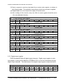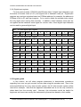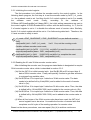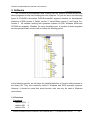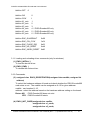
1
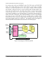
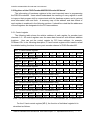
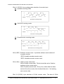
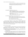
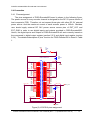
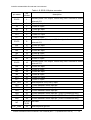
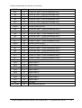
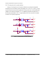
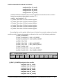
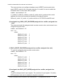
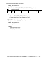
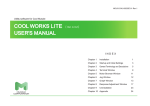
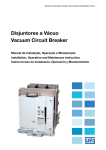
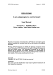
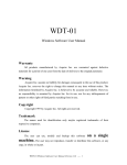
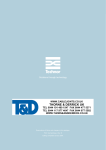
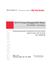
PISO-Encoder600/PISO-Encoder300 User’s Manual
PISO-Encoder600/PISO-Encoder300
6-axis/3axis 32-bit Encoder Card
User’s Manual
Version 1.0 04/2005 Edition
Driver update: http://www.icpdas.com
Warranty: All products manufactured by ICP DAS are warranted against defective
materials for one year from the date of delivery to the original purchaser
Warning: ICP DAS assumes no liability for damage consequent to the use of this
product. ICP DAS reserves the right to change this manual at any time without
notice. The information furnished by ICP DAS is believed to be accurate and
reliable. However, no responsibility is assumed by ICP DAS for its use, nor for any
infringements of patents or other rights of third parties resulting from its use.
Copyright
Copyright 2002 by ICP DAS. All rights are reserved
Trademark
The names used for identification only may be registered trademarks of their
respective companies.
PISO-Encoder600/ PISO-Encoder300 User’s Manual (Rev. 1.1, April/2005 PPH-018-10 ) ----- -1-
PISO-Encoder600/PISO-Encoder300 User’s Manual
Contents of PISO-Encoder600/PISO-Encoder300 Encoder Card
1 General information ...............................................................................................................................3
1.1 Introduction......................................................................................................................................3
1.2 Key Features ....................................................................................................................................3
1.3 System Block Diagram ....................................................................................................................3
2 Hardware ...............................................................................................................................................5
2.1 Hardware address selection .............................................................................................................5
2.2 Registers of the PISO-Encoder600/PISO-Encoder300 board .........................................................7
2.2.1 Control register .........................................................................................................................7
2.2.2 Counter value register .............................................................................................................9
2.2.3 Digital output register............................................................................................................10
2.2.4 Digital input register...............................................................................................................11
2.3 Program guide................................................................................................................................11
2.3.1 Initializing the control register ...............................................................................................12
2.3.2 Reading the X1-axis 32-bits encoder counter value ..............................................................12
2.4 Connection .....................................................................................................................................14
2.4.1 Pins assignment .....................................................................................................................14
2.4.3 The internal circuit of encoder interface ...............................................................................17
2.4.3 Internal circuit of digital inputs HR1~HR6 ..........................................................................18
2.4.4 Internal circuit of digital outputs DO1~DO8 ........................................................................18
2.4.5 The connection of encoder ....................................................................................................19
3. Software ..............................................................................................................................................20
3.1 Functions........................................................................................................................................20
3.1.1 Loading and unloading driver commands (only for windows)..............................................21
3.2.2 Commands ..............................................................................................................................21
4. Driver ..................................................................................................................................................25
4.1 DOS Driver (C, C++) ....................................................................................................................25
4.2 Windows 95/98 Driver ..................................................................................................................25
4.3 Windows NT Driver ......................................................................................................................25
5. Example................................................................................................................................................27
5.1 Dos examples.................................................................................................................................27
5.2 Windows installation .....................................................................................................................28
5.3 Windows examples ........................................................................................................................29
PISO-Encoder600/ PISO-Encoder300 User’s Manual (Rev. 1.1, April/2005 PPH-018-10 ) ----- -2-
PISO-Encoder600/PISO-Encoder300 User’s Manual
1 General information ________________________________
1.1 Introduction
The PISO-Encoder600/PISO-Encoder300 is a high performance and high speed 6–
axis/3-axis 32-bit PCI bus Encoder Card for the IBM compatible PC. The high-end
specifications of this encoder card and complete software support make it ideal for wide
range applications in position measurement of motion systems for industrial and
laboratory environment. The key features are described as below.
1.2 Key Features
6-axis Encoder counter
True 32 bits counter
PCI bus
Maximum counting rate: 1MHz.
3rd-order internal digital filter.
Counting mode: Quadrant, CW_CCW, PULSE_DIR
A+, A-, B+, B-, C+, C- inputs.
Programmable reset counter function.
Index (C channel) reset counter function.
Hardware reset (HR1~HR6), reset counter function
SCSI-II 68-pin connector.
8 digital outputs (DO1~DO8), 6 digital inputs (HR1~HR6).
2500V optical isolation.
DOS, Windows 95/98, Windows NT/2000 drivers.
BCB, VB and Delphi demos (with source code).
PISO-Encoder300 only has 3-axis (x1,x2,x3), 3-index (c1,c2,c3), and 3
hardware Reset (HR1,HR2,HR3)
Optional daughter board
An optional DN-68 SCSI-II (68 Pins) daughter board comes with connection
Cable. It provides easy installation with PISO-Encoder600 and hardware
system.
1.3 System Block Diagram
The PISO-Encoder600 has a 6-axis encoder counter. And each axis has a 32-bit
true counter with maximum counting rate of 1MHz. It also offers three different types of
PISO-Encoder600/ PISO-Encoder300 User’s Manual (Rev. 1.1, April/2005 PPH-018-10 ) ----- -3-
PISO-Encoder600/PISO-Encoder300 User’s Manual
the counting mode, which are QUADRANT mode, CW_CCW mode, and PULSE_DIR
mode. User should choose the correct mode based on actual type of encoder.
Otherwise, the PISO-Encoder600 will not work properly. Besides, PISO-Encoder600
also provides 3 different functions of counter resetting mode including register reset,
index reset and hardware reset. The Index reset function is used to reset encoder
counter through using a C+/C- channel signal during every revolution. The hardware
reset function is adopted to reset encoder counter by a pre-defined external signal pin,
namely HR1~HR6. Furthermore, when PISO-Encoder600 is not set on the hardware
reset mode, the pins of HR1~HR6 can be open as digital inputs. In addition, PISOEncoder600 also offers 8 channels of digital output. Every digital output and input (digital
I/O) is photo-coupled isolated up to 2500Vrms. The detailed function block diagram of
PISO-Encoder600 is demonstrated and summarized in the following figure.
X1,X2,X3
SCSI-II
connector
digital
input
digital
output
2500Vrms
photocoupled
isolation
32-bit
encoder
counter
X4,X5,X6
32-bit
encoder
counter
PCI bridge
Figure 1: block diagram of PISO-Encoder600
PISO-Encoder600/ PISO-Encoder300 User’s Manual (Rev. 1.1, April/2005 PPH-018-10 ) ----- -4-
PISO-Encoder600/PISO-Encoder300 User’s Manual
2 Hardware
_ ____
2.1 Hardware address selection
The hardware address of PISO-Encoder600 board can be set as 0~15 by DIP
switch A0~A3 on the PISO-Encoder600 board, as shown in Figure 2. The factory
hardware address setting is Hex 00. If the default address of this card is used by other
device, user can change the setting to various base addresses. The addressing of PCI
bus is defined in Table 1. According to the hardware address setting, programmer
should call function ENC6_REGISTRATION(cardNo, address) to confirm with the
hardware setting in the beginning of the program. The more detailed description for
function of ENC6_REGISTRATION() will be presented in chapter 3.
0x00 =
A0 A1 A2 A3
0x0F =
A0 A1 A2 A3
Figure 2 Hardware address selection
Table 1: Hardware address setting
PCI Address
A0
A1
A2
0*
0
0
0
1
1
0
0
2
0
1
0
3
1
1
0
4
0
0
1
5
1
0
1
6
0
1
1
7
1
1
1
8
0
0
0
9
1
0
0
10
0
1
0
11
1
1
0
12
0
0
1
13
1
0
1
14
0
1
1
15
1
1
1
A3
0
0
0
0
0
0
0
0
1
1
1
1
1
1
1
1
PISO-Encoder600/ PISO-Encoder300 User’s Manual (Rev. 1.1, April/2005 PPH-018-10 ) ----- -5-
PISO-Encoder600/PISO-Encoder300 User’s Manual
Note: On=0, OFF=1 ,* factory setting
PISO-Encoder600/ PISO-Encoder300 User’s Manual (Rev. 1.1, April/2005 PPH-018-10 ) ----- -6-
PISO-Encoder600/PISO-Encoder300 User’s Manual
2.2 Registers of the PISO-Encoder600/PISO-Encoder300 board
The information of hardware registers is the most important issue in programming
the PISO-Encoder600. Users should understand the meaning of every register in order
to improve their program skill to communicate with the hardware system and to get and
send information back and forth. A summary map of the address and data format of
each register is explained in the following sections. It should be noted that the addresses
of those registers are designated to the PCI base address.
2.2.1 Control register
The following table shows the relative address of each register for encoder input
channels 1~6. All control registers own the same data format but with different address
locations. User can set the control register by PCI base address, for example,
PCIBase+C0h. In the following description, X1-axis control register will be used to reveal
the detailed setting functions for every axis encoder channel of PISO-Encoder600.
WR1 X1-axis control register
Address
Type
C0h
W
MSB 7
6
CRST HRRST
5
4
3
2
1
0 LSB
B1
B0
/INH
/RST
S1
S0
5
4
3
2
1
0 LSB
B1
B0
/INH
/RST
S1
S0
5
4
3
2
1
0 LSB
B1
B0
/INH
/RST
S1
S0
WR2 X2-axis control register
Address
Type
C8h
W
MSB 7
6
CRST HRRST
WR3 X3-axis control register
Address
Type
D0h
W
MSB 7
6
CRST HRRST
WR4 X4-axis control register ( PISO-Encoder600 only )
Address
Type
D8h
W
MSB 7
6
CRST HRRST
5
4
3
2
1
0 LSB
B1
B0
/INH
/RST
S1
S0
WR5 X5-axis control register ( PISO-Encoder600 only )
Address
Type
E0h
W
MSB 7
6
CRST HRRST
5
4
3
2
1
0 LSB
B1
B0
/INH
/RST
S1
S0
WR6 X6-axis control register ( PISO- Encoder600 only )
Address
Type
E8h
W
MSB 7
6
CRST HRRST
5
4
3
2
1
0 LSB
B1
B0
/INH
/RST
S1
S0
Note: The above addresses are based on the PCI base address. (ex. PCIBase+C0h.)
For the X1-axis control register(WR1), the function of individual register bit is
described as follows:
PISO-Encoder600/ PISO-Encoder300 User’s Manual (Rev. 1.1, April/2005 PPH-018-10 ) ----- -7-
PISO-Encoder600/PISO-Encoder300 User’s Manual
Bits 1,0 (S1,S0): the counting mode selection of encoder input.
00 : quadrant-counting mode
A
B
counter
1 2
3 4 5 6
Quadrant Counting Mode
01 : CW/CCW counting mode
CW
CCW
counter
1
2
3
2
1
CW/CCW Counting Mode
X2=0
10 : Pulse/Direction counting mode
Pulse
Direction
counter
X2=0
1
2
3
2
1
Pulse/Direction Counting Mode
Bit 2 (/RST): Software counter reset. It provides software reset method of
encoder counter.
/RST=0 enable encoder counter reset.
/RST=1 disable encoder counter reset.
Bit 3 (/INH): inhibit counter value latch.
/INH=0 inhibit counter latch. This bit should be set to 0 before
reading out the counter value.
/INH=1 enable counter latch. Every time, when data has been
read out from the counter, this bit should be set to 1 for latching
next counter data.
Bits 5,4 (B1,B0): byte selection of 32-bit counter value. The data of 32-bit
PISO-Encoder600/ PISO-Encoder300 User’s Manual (Rev. 1.1, April/2005 PPH-018-10 ) ----- -8-
PISO-Encoder600/PISO-Encoder300 User’s Manual
counter value is stored in 4 bytes. Only one byte data can be
read out for each time. Therefore, B1 and B0 of control register
are designated to select which byte will be chosen.
00: byte 0
01: byte 1
10: byte 2
11: byte 3
Bit 6 (HRRST): Disable/Enable hardware reset.
HRRST=1 enable hardware input to reset encoder counter.
That is, when HRRST=1 and HRn is connected to EXT_GND,
encoder counter n will be reset to 0, where n indicates the
encoder number (n = 1, 2, … 6).
HRRST=0 disable hardware reset of counter value.
Bit 7 (CRST): Disable/Enable encoder index reset (C+/C-).
CRST=1 enable counter reset function by encoder index signal.
That is, encoder counter value will be reset to 0 by encoder index
(C+/C-) signal during every revolution.
CRST=0 disable the function of encoder index reset.
From the above description, the control register of PISO-Encoder600 board
provides three types of counter value resetting mode, which are software reset,
hardware reset and encoder index reset. User should carefully choose proper reset
method according to software and hardware environment. Otherwise, encoder counter
will be reset by the first coming resetting signal.
2.2.2 Counter value register
Counter value registers are read-type registers, which is based on PCI address (Ex:
PCIBase+C0h for X1-axis counter value, …), described in the table shown below.
These registers are used to read out the encoder counter value. The reading procedure
of encoder counter value is described as follows:
(1) Before reading the counter value, the /INH of control register should be set to 0
to inhibit data latch.
(2) The B1,B0 of control register should be set as 0~3 to assign which byte will be
read out. The counter value of 32-bit encoder has four-byte data. Note that only
one byte can be read out every time.
PISO-Encoder600/ PISO-Encoder300 User’s Manual (Rev. 1.1, April/2005 PPH-018-10 ) ----- -9-
PISO-Encoder600/PISO-Encoder300 User’s Manual
(3) Send a request to read one byte data from counter value register, as shown in
the following table. The address is according to which axis encoder is applied.
(4) Repeat steps (2)~(3) to acquire four bytes of counter value.
(5) After reading out the counter value, the /INH of control register should be set to
1 for next data latch function.
RD1
X1-axis counter value register
address
Type
C0h
R
RD2
Type
C8h
R
Type
D0h
R
Type
D8h
R
3
2
1
0 LSB
2
1
0 LSB
2
1
0 LSB
2
1
0 LSB
2
1
0 LSB
2
1
0 LSB
counter value
MSB 7
6
5
4
3
counter value
MSB 7
6
5
4
3
Counter value
MSB 7
6
5
4
3
counter value
X5-axis counter value register ( PISO-Encoder600 only )
address
Type
E0h
R
RD6
4
X4-axis counter value register ( PISO-Encoder600 only )
address
RD5
5
X3-axis counter value register
address
RD4
6
X2-axis counter value register
address
RD3
MSB 7
MSB 7
6
5
4
3
counter value
X6-axis counter value register ( PISO-Encoder600 only )
address
Type
E8h
R
MSB 7
6
5
4
3
counter value
2.2.3 Digital output register
PISO-Encoder600 offers 8 digital output channels. Digital output register is writetype register, locating at the address of PCIBase+C4h, to send out information through
digital output channels. The data format of the digital output register is depicted below.
DO register
address
Type
MSB 7
6
5
4
3
2
1
0 LSB
C4h
W
DO7
DO6
DO5
DO4
DO3
DO2
DO1
DO0
PISO-Encoder600/ PISO-Encoder300 User’s Manual (Rev. 1.1, April/2005 PPH-018-10 ) ----- -10-
PISO-Encoder600/PISO-Encoder300 User’s Manual
2.2.4 Digital input register
For every axis encoder, PISO-Encoder600 also offers 2 digital input channels to get
the status of encoder index (C+/C-) and signal level of hardware reset pin. Digital input
registers are read-type registers based on PCIBase address, for example, the address is
PCIBase+C4h for X1-axis input register. Cn is used to obtain the encoder index signal,
the only signal level coming from encoder. In addition, when hardware reset pins are
not applied as the hardware reset signal for counter value, those digital input channels
can be used for general digital input.
RD11 X1-axis digital input register
address
Type
MSB 7
6
5
4
3
2
1
0 LSB
C4h
R
--
--
--
--
--
--
C1
HR1
RD21 X2-axis digital input register
address
Type
MSB 7
6
5
4
3
2
1
0 LSB
CCh
R
--
--
--
--
--
--
C2
HR2
RD31 X3-axis digital input register
address
Type
MSB 7
6
5
4
3
2
1
0 LSB
D4h
R
--
--
--
--
--
--
C3
HR3
RD41 X4-axis digital input register ( PISO- Encoder600 only )
address
Type
MSB 7
6
5
4
3
2
1
0 LSB
DCh
R
--
--
--
--
--
--
C4
HR4
RD51 X5-axis digital input register ( PISO- Encoder600 only )
address
Type
MSB 7
6
5
4
3
2
1
0 LSB
E4h
R
--
--
--
--
--
--
C5
HR5
RD61 X6-axis digital input register ( PISO- Encoder600 only )
address
Type
MSB 7
6
5
4
3
2
1
0 LSB
ECh
R
--
--
--
--
--
--
C6
HR6
2.3 Program guide
In this section, we will show program statements to demonstrate procedures
regarding how user can get encoder counter data using this encoder card. Due to the
same specifications for every axis encoder system, the X1-axis encoder system will be
used as an example. Note that the approach described here is not the only method to
obtain data from the encoder card. However, this information would be helpful for
beginners and users can modify the statements by themselves based on their needs.
PISO-Encoder600/ PISO-Encoder300 User’s Manual (Rev. 1.1, April/2005 PPH-018-10 ) ----- -11-
PISO-Encoder600/PISO-Encoder300 User’s Manual
2.3.1 Initializing the control register
The first procedure is to initialize the encoder card by the control register. In the
following demo program, the first step is to set the encoder mode by 0x3C | x1_mode,
i.e., the quadrant mode is set. And then the bit 2 of control register is set to 0 to enable
the
software
reset
mode.
Finally,
according
to
the
address
of
PCIBase+WR1(card[cardNo].ctrl1.base+WR1), the initial setting parameters are sent to
the control register of PISO-Encoder600 to confirm with the above setting. In 2, the bit
2 of control register is set to 1 to disable the software reset of counter value. Similarly,
the bit 3 of control register should be set to 1 for forthcoming data latch. Therefore, the
X1-axis encoder is ready to work.
1 x1_mode = ENC_QUADRANT; // ENC_QUADRANT is a pre-defined constant
0x00
card[cardNo].ctrl1 = 0x3C | x1_mode; //xx11 11xx, set the counting mode
//enable software encoder reset mode,
card[cardNo].ctrl1 &= 0xFB; //1111 1011, set bit2=0 to reset the encoder counter.
outportb(card[cardNo].base + WR1, card[cardNo].ctrl1);
2 card[cardNo].ctrl1 |= 0x04; //0000 0100, set bit2=1 to complete the reset.
outportb(card[cardNo].base + WR1, card[cardNo].ctrl1);
2.3.2 Reading the X1-axis 32-bits encoder counter value
After initializing the encoder card, the program stated below is designated to acquire
32-bit encoder counter value, which is described in section 2.2.2.
(3a) Set the /INT=0 to inhibit counter latch. And Set B1,B0 as 00 to import byte 0
data of 32-bit counter value. Finally call inportb() function to get data and store
in unsigned long variable value;
(3b) Set B1,B0 as 01 to import byte 1 data from 32-bit counter value. The data
needs to be shifted left by 8 bits(256L) and is added to the result of counter
value in (3a);
(3c) Set B1,B0 as 10 to import byte 2 data from 32-bit counter value. Then, the data
is shifted left by 16 bits(256L*256L) and is added to the counter value in (3b);
(3d) Set B1,B0 as 11 to import byte 3 data from 32-bit counter value. Then, the data
is shifted left by 24 bits(256L*256L*256L) and is added to the counter value in
(3c);
(4) When all four bytes of the 32-bit counter value have been read, the /INT bit of
control register has to be set as 1 to enable the function of counter latch that
completes one full cycle of the reading operation for counter value.
Based on the above procedures, user can repeat (3a)~(4) to achieve continuous
PISO-Encoder600/ PISO-Encoder300 User’s Manual (Rev. 1.1, April/2005 PPH-018-10 ) ----- -12-
PISO-Encoder600/PISO-Encoder300 User’s Manual
acquisition of encoder counter value.
unsigned long value;
3a card[cardNo].ctrl1 &= 0xC7; //1100 0111, set bit3=0 and select byte 0 to read
outportb(card[cardNo].base + WR1, card[cardNo].ctrl1);
value = (unsigned long)inportb(card[cardNo].base + RD1);
3b card[cardNo].ctrl1 |= 0x10; //0001 0000, select byte 1 to read
outportb(card[cardNo].base + WR1, card[cardNo].ctrl1);
value += (unsigned long)(inportb(card[cardNo].base + RD1)*256L);
3c card[cardNo].ctrl1 &= 0xC7; //1100 0111, clear bits 5,4 of control register
card[cardNo].ctrl1 |= 0x20; //0010 0000, select byte 2 to read
outportb(card[cardNo].base + WR1, card[cardNo].ctrl1);
value += (unsigned long)(inportb(card[cardNo].base + RD1)*256L*256L);
3d card[cardNo].ctrl1 |= 0x30; //0011 0000, select byte 3 to read
outportb(card[cardNo].base + WR1, card[cardNo].ctrl1);
value += (unsigned long)(inportb(card[cardNo].base + RD1)*256L*256L*256L);
4 card[cardNo].ctrl1 |= 0x38; //0011 1000, set bit3=1
outportb(card[cardNo].base + WR1, card[cardNo].ctrl1);
PISO-Encoder600/ PISO-Encoder300 User’s Manual (Rev. 1.1, April/2005 PPH-018-10 ) ----- -13-
PISO-Encoder600/PISO-Encoder300 User’s Manual
2.4 Connection
2.4.1 Pins assignment
The pins assignment of PISO-Encoder600 board is shown in the following figure.
The power source of every encoder channel is designed for the DC 5V power source of
host computer’s PCB. Therefore, do not connect those pins with other DC 5V external
power source. And the maximum current of each encoder power is 100mA. Besides,
user should apply external DC 24V power source across pins of EXT_VCC and
EXT_GND in order to use digital inputs and outputs provided in PISO-Encoder6000.
Hence, the digital inputs and outputs of PISO-Encoder600 will work correctly based on
the commands in digital output register (section 2.2.3) and digital input register (section
2.2.4). The detailed description of pins’ function for PISO-Encoder600 is listed in Table
1.
E5V
F1
FUSE
DIP
J2
SCSI-II-68FEMALE
EVCC
1A+
1A1B+
1B1C+
EVCC 1C2A+
2A2B+
2B2C+
EVCC 2C-
EXT_VCC
3A+
3A3B+
3B3C+
3CHR1
HR2
HR3
HR4
HR5
HR6
EXT_GND
1
2
3
4
5
6
7
8
9
10
11
12
13
14
15
16
17
18
19
20
21
22
23
24
25
26
27
28
29
30
31
32
33
34
35
36
37
38
39
40
41
42
43
44
45
46
47
48
49
50
51
52
53
54
55
56
57
58
59
60
61
62
63
64
65
66
67
68
D33
1N4002
DIP
EGND
4A+
4A4B+
4B4C+
4C5A+
5A5B+
5B5C+
5C-
EGND
EGND
EGND
6A+
6A6B+
6B6C+
6C-
EXT_VCC
DO0
DO1
DO2
DO3
DO4
DO5
DO6
DO7
EXT_VCC
D34
1N4002
DIP
EXT_GND
EXT_GND
Figure(3) J2 SCSI-II pins assignment
PISO-Encoder600/ PISO-Encoder300 User’s Manual (Rev. 1.1, April/2005 PPH-018-10 ) ----- -14-
PISO-Encoder600/PISO-Encoder300 User’s Manual
Table1: J2 SCSI-II 68-pins connector
pin name
pin
number
description
EVCC
1
encoder power +5V output, 100mA only, don’t connect to others
external +5V.
1A+
2
X1-axis A+ input
1A-
3
X1-axis A- input
1B+
4
X1-axis B+ input
1B-
5
X1-axis B- input
1C+
6
X1-axis C+ input
1C-
7
X1-axis C- input
EVCC
8
encoder power +5V output, 100mA only, don’t connect to others
external +5V.
2A+
9
X2-axis A+ input
2A-
10
X2-axis A- input
2B+
11
X2-axis B+ input
2B-
12
X2-axis B- input
2C+
13
X2-axis C+ input
2C-
14
X2-axis C- input
EVCC
15
encoder power +5V output, 100mA only, don’t connect to others
external +5V.
3A+
16
X3-axis A+ input
3A-
17
X3-axis A- input
3B+
18
X3-axis B+ input
3B-
19
X3-axis B- input
3C+
20
X3-axis C+ input
3C-
21
X3-axis C- input
EXT_VCC
22
external power VCC(+24V) input
HR1
23
X1-axis hardware reset input pin
HR2
24
X2-axis hardware reset input pin
HR3
25
X3-axis hardware reset input pin
HR4
26
X4-axis hardware reset input pin ( PISO- Encoder600 only )
HR5
27
X5-axis hardware reset input pin ( PISO- Encoder600 only )
HR6
28
X6-axis hardware reset input pin ( PISO- Encoder600 only )
NC
EXT_GND
29,30,31, Not used
32,33
34
external power ground
PISO-Encoder600/ PISO-Encoder300 User’s Manual (Rev. 1.1, April/2005 PPH-018-10 ) ----- -15-
PISO-Encoder600/PISO-Encoder300 User’s Manual
EGND
35
encoder power ground
4A+
36
X4-axis A+ input ( PISO-Encoder600 only )
4A-
37
X4-axis A- input ( PISO-Encoder600 only )
4B+
38
X4-axis B+ input ( PISO-Encoder600 only )
4B-
39
X4-axis B- input ( PISO-Encoder600 only )
4C+
40
X4-axis C+ input ( PISO-Encoder600 only )
4C-
41
X4-axis C- input ( PISO-Encoder600 only )
EGND
42
encoder power ground
5A+
43
X5-axis A+ input ( PISO-Encoder600 only )
5A-
44
X5-axis A- input ( PISO-Encoder600 only )
5B+
45
X5-axis B+ input ( PISO-Encoder600 only )
5B-
46
X5-axis B- input ( PISO-Encoder600 only )
5C+
47
X5-axis C+ input ( PISO-Encoder600 only )
5C-
48
X5-axis C- input ( PISO-Encoder600 only )
EGND
49
encoder power ground
6A+
50
X6-axis A+ input ( PISO-Encoder600 only )
6A-
51
X6-axis A- input ( PISO-Encoder600 only )
6B+
52
X6-axis B+ input ( PISO-Encoder600 only )
6B-
53
X6-axis B- input ( PISO-Encoder600 only )
6C+
54
X6-axis C+ input ( PISO-Encoder600 only )
6C-
55
X6-axis C- input ( PISO-Encoder600 only )
EXT_VCC
56
external power VCC(+24V) input
DO0
57
digital output 0
DO1
58
digital output 1
DO2
59
digital output 2
DO3
60
digital output 3
DO4
61
digital output 4
DO5
62
digital output 5
DO6
63
digital output 6
DO7
64
digital output 7
NC
EXT_GND
65,66,67 Not used
68
external power ground
PISO-Encoder600/ PISO-Encoder300 User’s Manual (Rev. 1.1, April/2005 PPH-018-10 ) ----- -16-
PISO-Encoder600/PISO-Encoder300 User’s Manual
2.4.3 The internal circuit of encoder interface
In figure 4, the internal circuit of encoder interface for one channel is presented.
According to the circuit shown in below, the signals of A+, A-, B+, B-, C+ and C- of every
encoder channel are all needed for application of this encoder card. And the differential
voltage of every signal (for example, A+, A-) is applied to guarantee the signal level. If
the encoder only provides A+, B+, C+ signal, please refer to the connection of encoder
in section 2.4.5 to pull up signal level.
VCC
3.3K
330R
6
5
4
/A
1
1A+
3
DGND
1A-
VCC
3.3K
330R
6
5
4
/B
1
1B+
3
DGND
1B-
VCC
3.3K
330R
/CC1
470p
4
1
3
2
1C+
1CDGND
PISO-ENC600
Figure 4: Internal circuit of encoder interface
PISO-Encoder600/ PISO-Encoder300 User’s Manual (Rev. 1.1, April/2005 PPH-018-10 ) ----- -17-
PISO-Encoder600/PISO-Encoder300 User’s Manual
2.4.3 Internal circuit of digital inputs HR1~HR6
When HRn is connected to a low level signal, the corresponding digital input
register will be 1. Otherwise, when HRn is connected to a high level signal(DC24V), the
corresponding digital input register will become 0.
EXT_VCC
3.3K
4
1
3
2
HR1
PISO-ENC600
EXT_GND
External
Figure 5. Internal circuit of HR(hardware reset)
2.4.4 Internal circuit of digital outputs DO0~DO7
The load should locate between an external power source and a digital output
terminal. When user send command to output register to trigger photo-coupled
transister, the load will be actived by the external power source.
EXT_VCC
DO1
1
4
2
3
Load
EXT_GND
PISO-ENC600
External
Figure 6: Internal circuit of DO(digital output)
PISO-Encoder600/ PISO-Encoder300 User’s Manual (Rev. 1.1, April/2005 PPH-018-10 ) ----- -18-
PISO-Encoder600/PISO-Encoder300 User’s Manual
2.4.5 The connection of encoder
The typical connection of encoder and PISO-Encoder600 is shown in Figure 7.
However, if the encoder only provides A+, B+, C+ , GND and 5V connection, which is
called open-collector type encoder, we need to add exteral resistors to pull up voltage as
shown in Figure 8. In general, the pull-up resistance is suggested to be 10KΩ, but it
may vary with specifications of different encoders.
CN4
J2
A+
AB+
BC+
C-
Encoder
5V
GND
1A+
1A1B+
1B1C+
1C5V
GND
Figure 7. Connection between encoder and PISO-Encoder600 card
CN4
J2
Encoder
A+
B+
C+
5V
GND
1A+
1A1B+
1B1C+
1C5V
GND
open collector
type encoder
Figure 8: Connection of open-collector type encoder
PISO-Encoder600/ PISO-Encoder300 User’s Manual (Rev. 1.1, April/2005 PPH-018-10 ) ----- -19-
PISO-Encoder600/PISO-Encoder300 User’s Manual
3. Software
_ __________
The CD-ROM of development tools coming with the product includes drivers and
demo programs to help user building their own systems. As you can see in the following
figure of CD-ROM’s directories, PISO-Encoder600 supports software for development
platforms of BCB version 3, Delphi version 3, Visual Basic version 5, and Visual C++
version 5. All software working with operation systems of DOS, Windows 95/98 and
NT/2000 are supplied. Besides, for every developing tool, a number of demo programs
are also provided with source code to reduce the learning period.
In the following section, we will show the detailed definition of function calls provided in
the library file. They are commonly useful in Windows and DOS operation systems.
However, it should be noted that some function calls can only be used in Windows
environment.
3.1 Functions
Constants
#define YES
#define NO
#define ON
1
0
1
PISO-Encoder600/ PISO-Encoder300 User’s Manual (Rev. 1.1, April/2005 PPH-018-10 ) ----- -20-
PISO-Encoder600/PISO-Encoder300 User’s Manual
#define OFF
0
#define CW
#define CCW
#define X1_axis
#define X2_axis
#define X3_axis
#define X4_axis
#define X5_axis
#define X6_axis
0
1
1
2
3
4 // PISO-Encoder600 only
5 // PISO-Encoder600 only
6 // PISO-Encoder600 only
#define ENC_QUADRANT
#define ENC_CW_CCW
#define ENC_PULSE_DIR
0x00
0x01
0x02
#define ENC_HR_RESET
0x40
#define ENC_INDEX_RESET 0x80
3.1.1 Loading and unloading driver commands (only for windows)
(1) ENC6_INITIAL( )
To load the device driver.
(2) ENC6_END( )
To release the device driver.
3.2.2 Commands
(3) unsigned char ENC6_REGISTRATION(unsigned char cardNo, unsigned int
address)
To select the hardware address of board and check whether the PISO-Encoder600
card exists or not. The cardNo can be assigned as 0~15 for given address.
cardNo : card number 0~15.
address : select the address based on the hardware address setting on the board.
Return NO : PISO-Encoder600 does not exist
YES : PISO-Encoder600 exists
(4) ENC6_INIT_CARD(unsigned char cardNo,
unsigned char x1_mode,
unsigned char x2_mode,
PISO-Encoder600/ PISO-Encoder300 User’s Manual (Rev. 1.1, April/2005 PPH-018-10 ) ----- -21-
PISO-Encoder600/PISO-Encoder300 User’s Manual
unsigned char x3_mode,
unsigned char x4_mode,
unsigned char x5_mode,
unsigned char x6_mode)
Initialize PISO-Encoder600 card’s control registers and set all encoder counters
based on procedures described in section 2.3.1.
cardNo : card number 0~15.
x1_mode: The value of X1-axis control register;
x2_mode: The value of X2-axis control register;
x3_mode: The value of X3-axis control register;
x4_mode: The value of X4-axis control register;
x5_mode: The value of X5-axis control register;
x6_mode: The value of X6-axis control register;
According the control register table, shown in below, the encoder mode and counter
resetting mode of every axis encoder can be set as the one of the following selections.
(1) ENC_QUADRANT
(2) ENC_QUADRANT | ENC_HR_RESET;
(3) ENC_QUADRANT | ENC_INDEX_RESET;
(4) ENC_CW_CCW
(5) ENC_CW_CCW | ENC_HR_RESET;
(6) ENC_CW_CCW | ENC_INDEX_RESET;
(7) ENC_PULSE_DIR
(8) ENC_PULSE_DIR | ENC_HR_RESET;
(9) ENC_PULSE_DIR | ENC_INDEX_RESET;
WR1
X1-axis control register
address
Type
C0h
W
MSB 7
6
CRST HRRST
5
4
3
2
1
0 LSB
B1
B0
/INH
/RST
S1
S0
(5) ENC6_CONFIG(unsigned char cardNo,
unsigned char x1_mode,
unsigned char x2_mode,
unsigned char x3_mode,
unsigned char x4_mode,
unsigned char x5_mode,
unsigned char x6_mode);
PISO-Encoder600/ PISO-Encoder300 User’s Manual (Rev. 1.1, April/2005 PPH-018-10 ) ----- -22-
PISO-Encoder600/PISO-Encoder300 User’s Manual
This command can only configure hardware reset (HRRST) and encoder index
reset (CRST) mode for all of encoder channels. It is useful for user to enable the
hardware reset or index reset within program.
cardNo : card number 0~15.
x1_mode,x2_mode,x3_mode,x4_mode,x5_mode, and x6_mode are the control
registers for every axis encoder as described in the above function.
Where x4_mode , x5_mode , x6_mode could be to 0 if PISO-Encoder300 card.
(6) unsigned long ENC6_GET_ENCODER(unsigned char cardNo, unsigned char
axis)
This command reads the assigned axis's encoder counter value, and returns it as a
unsigned long type value.
cardNo : card number 0~15.
axis : 1~6.
where
#define X1_axis
#define X2_axis
#define X3_axis
#define X4_axis
#define X5_axis
#define X6_axis
1
2
3
4
5
6
(7) ENC6_RESET_ENCODER(unsigned char cardNo, unsigned char axis)
To reset the assigned axis's encoder counter value.
cardNo : card number 0~15.
axis : 1~6.
where
#define X1_axis
1
#define X2_axis
2
#define X3_axis
3
#define X4_axis
4
#define X5_axis
5
#define X6_axis
6
(8) unsigned char ENC6_GET_INDEX(unsigned char cardNo, unsigned char
axis)
To get the assigned axis's input register. The contents of input register, C1(index),
HR1(hardware reset) can be obtained using this command.
PISO-Encoder600/ PISO-Encoder300 User’s Manual (Rev. 1.1, April/2005 PPH-018-10 ) ----- -23-
PISO-Encoder600/PISO-Encoder300 User’s Manual
cardNo : card number 0~15.
axis : 1~6
Return the value of RD11(RD21,RD31,RD41,RD51,RD61) input register
RD11
X1-axis input register
address
Type
MSB 7
6
5
4
3
2
1
0 LSB
C4h
R
--
--
--
--
--
--
C1
HR1
Example:
x1_index = ENC6_GET_INDEX(CARD1,X1_axis);
x2_index = ENC6_GET_INDEX(CARD1,X2_axis);
(9) ENC6_DO(unsigned char cardNo, unsigned char value)
To output value to the DO1~DO8.
cardNo : card number 0~15.
value : output value.
Example:
ENC6_DO(CARD1,0x22);
ENC6_DO(CARD1,0x00);
PISO-Encoder600/ PISO-Encoder300 User’s Manual (Rev. 1.1, April/2005 PPH-018-10 ) ----- -24-
PISO-Encoder600/PISO-Encoder300 User’s Manual
4. Driver
_
4.1 DOS Driver (C, C++)
Item
File
Header file
enc600.h
Library file
enc600.lib
Example file
(turbo C++):
demo.prj
demo1.prj
demo2.prj
4.2 Windows 95/98 Driver
Item
File
Header file
enc600.h
Import Library file
enc600.lib
bcenc600.lib (only for Borland C++)
Dynamic Link Library
enc600.dll (copy to c:\Windows\system)
Driver
Napdio.vxd (copy to c:\Windows\system)
Example file
(Borland C++ Builder):
enc6demo.bpr
enc6demo1.bpr
(Delphi):
enc6demo.dpr
enc6demo1.dpr
(VB):
enc6demo.vbp
enc6demo1.vbp
4.3 Windows NT Driver
Item
File
Header file
enc600.h
Import Library file
enc600.lib
bcenc600.lib (only for Borland C++)
Dynamic Link Library
enc600.dll(copy to c:\WinNT\System32)
PISO-Encoder600/ PISO-Encoder300 User’s Manual (Rev. 1.1, April/2005 PPH-018-10 ) ----- -25-
PISO-Encoder600/PISO-Encoder300 User’s Manual
Driver
regdrv.bat
napwnt.ini
napwnt.sys (copy to c:\WinNT\System32\drivers)
regini.exe
Example file
(Borland C++ Builder):
enc6demo.bpr
enc6demo1.bpr
(Delphi):
enc6demo.dpr
enc6demo1.dpr
(VB):
enc6demo.vbp
enc6demo1.vbp
PISO-Encoder600/ PISO-Encoder300 User’s Manual (Rev. 1.1, April/2005 PPH-018-10 ) ----- -26-
PISO-Encoder600/PISO-Encoder300 User’s Manual
5. Example__________________________________________
5.1 Dos examples
(1) Demo.exe
The Demo.exe (in the directory: ..\….\PISO-Encoder\dos\c\demo) is an example
regarding how to use PISO-Encoder600 command sets to get encoder counter values.
Figure 9 displays the result of the Demo.exe when X1 and X2 channels are
connected with encoders. .
Figure (9) The result of the Demo.exe
(2) Demo1.exe
The Demo1.exe (in the directory: ..\….\PISO-Encoder\dos\c\demo1) uses the index
reset method (C+/C-) to reset the encoder counter value for each revolution. This
program is designed to test every axis encoder counter value for one revolution each
time. Figure 10 presents the results of demo program. The counter value is 3996 for
one revolution. According to hardware specification of the tested encoder is 1000, the
quadrant rate of encoder should be 4000 for one revolution. The difference between
the real value and the test value is caused by the counter value reset by the index
signal (C+/C-). That is, the last 4 counter values are not added, because encoder
index signal is high during the last A/B signal period and reset the counter value.
Therefore, user can add 4 to final counter value to get the correct counter value for
one revolution. And this demo program can be used to check specification for one
revolution (pulse/rev) of encoder.
PISO-Encoder600/ PISO-Encoder300 User’s Manual (Rev. 1.1, April/2005 PPH-018-10 ) ----- -27-
PISO-Encoder600/PISO-Encoder300 User’s Manual
Figure 10: The result of the Demo1.exe
5.2 Windows installation
(1) Installation for Windows 9x/ME
A. Installing hardware
Step 1. Shutdown and power off your computer.
Step 2. Plug the PISO-Encoder600 in the PCI slot.
Step 3. Power on your computer.
B. Windows Plug and Play (PnP)
Step 1. During Windows startup, it will find the PCI card and request user to
provide an INF file for Plug&Play. The INF file for PISO-Encoder600
is placed on the following folders.
1. D:\NAPDOS\Motion\PISO-Encoder\Win95\Inf\
(From the enclosed CD-ROM.)
2. C:\DAQPro\PISO-Encoder_Win95\Inf\
(From the hard disk, after installing the software.)
Step 2. Specify the above directory to provide the INF file for PnP.
C. Installing software
Step 1. Insert the CD into CD-ROM drive (for example: "D:")
Step 2. Click the "Start/Run" menu item in the task Bar.
Step 3. Enter the path as:
(if CD-ROM drive is D:)
PISO-Encoder600/ PISO-Encoder300 User’s Manual (Rev. 1.1, April/2005 PPH-018-10 ) ----- -28-
PISO-Encoder600/PISO-Encoder300 User’s Manual
D:\NAPDOS\Motion\PISO-Encoder\Win95\Setup\SETUP.EXE
Step 4. Follow instructions of the installation process.
D. After installation
The enc600.dll will be copied into C:\Windows\system.
The Napdio.vxd will be copied into C:\Windows\system.
(2) Installation for windows NT/2000
A. Installing hardware
Step 1. Shutdown and power off your computer.
Step 2. Plug the PISO-Encoder600 in the PCI slot.
Step 3. Power on your computer.
B. Installing software
Step 1. Insert the CD into CD-ROM drive (for example: "D:").
Step 2. Click the "Start/Run" menu item in the task Bar.
Step 3. Enter the path as:
(if CD-ROM drive is D:)
D: \NAPDOS\Motion\PISO-Encoder\WinNT\Setup\SETUP.EXE
Step 4. Follow instructions of the installation process.
C. After installation
The enc600.dll will be copied into C:\WINNT\SYSTEM32
The Napwnt.sys will be copied into C:\WINNT\SYSTEM32\DRIVERS
The following registry keys and values will also be created
HKEY_LOCAL_MACHINE:
system\CurrentControlSet\Services\Napwnt\ErrorControl=0x00000001
system\CurrentControlSet\Services\Napwnt\Start=0x00000002
system\CurrentControlSet\Services\Napwnt\Type=0x00000001
5.3 Windows examples
(1) enc6demo.exe
The enc6demo.exe (source codes included) is an example of the PISOEncoder600 board for Windows environment. It works in operation systems
Windows9x/ME and NT/2000. The function of this demo program is described as
follows. A pop-up panel as shown in Figure 11 is shown on the graphic display.
PISO-Encoder600/ PISO-Encoder300 User’s Manual (Rev. 1.1, April/2005 PPH-018-10 ) ----- -29-
PISO-Encoder600/PISO-Encoder300 User’s Manual
1. Setting area
You can select counting mode and hardware reset settings, then click on the
“Update parameter” button to setup the PISO-PS600.
2. Encoder status area
It shows the encoder counter value and C1~C6, HR1~HR6 status.
3. The selection check box of digital output is designed in the middle of the
panel. User can choose which digital outputs will be send out by the mouse.
Finally, user can click the Update Parameter bottom to active system. The encoder
counter value will be presented on the screen and digital output will also be sent out at
the same time. If user clicks the stop bottom, the demo program will stop to update the
encoder status.
Figure 11: The panel of the enc6demo.exe
PISO-Encoder600/ PISO-Encoder300 User’s Manual (Rev. 1.1, April/2005 PPH-018-10 ) ----- -30-
PISO-Encoder600/PISO-Encoder300 User’s Manual
(2) enc6demo1.exe
The function of enc6demo1.exe is the same with the demo program demo.exe in
DOS example. It can be used to test the encoder counter value for one revolution in
Windows 9x/ME or Windows NT/2000. The function of graphic interface is
designated as following:
1. At first, user select which axis encoder will be tested;
2. User clicks on “Start” Button. Then, the selected encoder counter value for
one revolution is displayed in middle of graphic interface.
3. The “Clear” button is used to clear the counter value shown in the figure and
prepare to display for next test procedure.
4. The “Exit” button is used to exit the program.
From the figure shown below, it shows the counter value is 3996 for one revolution.
The reason is that the hardware encoder has 1000pulse/revolution performance. After
quadrant rate of PISO-Encoder600, the counter value should be 4000 for one revolution.
Due to the encoder index reset mode is chosen to reset the counter value, therefore, the
last pulse A and B will not be included into the encoder card system and the counter
value becomes 3996. User can add 4 counter value to the final encoder value to get the
correct counter value for one revolution. Besides, this program can also be used to verify
the total pulses of unknown encoder specification for one revolution.
Figure 12: The panel of the enc6demo1.exe
PISO-Encoder600/ PISO-Encoder300 User’s Manual (Rev. 1.1, April/2005 PPH-018-10 ) ----- -31-