1
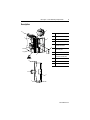
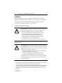
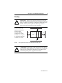
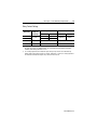
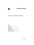
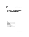
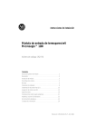
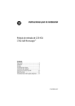
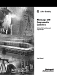
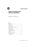
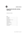
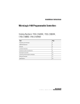
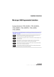
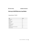
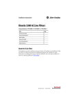
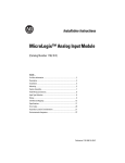
Installation Instructions
MicroLogix™ 1762-OW8 Relay Output Module
Inside
Description .......................................................3
Installation........................................................4
Mounting ..........................................................5
System Assembly .............................................7
Field Wiring Connections...................................7
I/O Memory Mapping ......................................10
Specifications .................................................11
Hazardous Location Considerations ................14
Environnements dangereux.............................15
1762-IN003A-US-P
2
MicroLogix™ 1762-OW8 Relay Output Module
For More Information
For
Refer to this Document
Information on installing, wiring, and
operating a MicroLogix 1200
Programmable Controller
MicroLogix 1200 Programmable 1762-UM001A-US-P
Controllers User Manual
Installation guide for the MicroLogix
1200 Programmable Controller.
MicroLogix 1200 Programmable 1762-IN006A-ML-P
Controllers Installation
Instructions
Installation guide for the MicroLogix
1200 Memory Module and Real Time
Clock.
MicroLogix 1200 Memory
1762-IN001A-US-P
Module and/or Real Time Clock
Installation Instructions
Installation guide for the 1762-IA8
Discrete Input Module
1762- IA8 120V ac Input Module 1762-IN002A-US-P
Installation Instructions
Installation guide for the 1762-IQ8
Discrete Input Module
1762-IQ8 DC Input Module
Installation Instructions
1762-IN004A-US-P
Installation guide for the 1762-IF2OF2
Analog I/O Module
1762-IF2OF2 Analog Input/
Output Module Installation
Instructions
1762-IN005A-US-P
More information on proper wiring and Industrial Automation Wiring
grounding techniques.
and Grounding Guidelines
Pub. No.
1770-4.1
If you would like a manual, you can:
• download a free electronic version from the internet:
www.ab.com/micrologix or www.theautomationbookstore.com
• purchase a printed manual by:
– contacting your local distributor or Rockwell Automation representative
– visiting www.theautomationbookstore.com and placing your order
– calling 1.800.963.9548 (USA/Canada)
or 001.330.725.1574 (Outside USA/Canada)
1762-IN003A-US-P
MicroLogix™ 1762-OW8 Relay Output Module
3
Description
9
1a
Item Description
7
3
5
6
1b
4
2
1a
1a
upper panel mounting tab
1b
lower panel mounting tab
2
I/O diagnostic LEDs
3
module door with terminal
identification label
4
bus connector
with male pins
5
bus connector cover
6
flat ribbon cable with bus
connector (female pins)
7
terminal block
8
DIN rail latch
9
pull loop
6
2
8
1b
1762-IN003A-US-P
4
MicroLogix™ 1762-OW8 Relay Output Module
Installation
1762 I/O is suitable for use in an industrial environment when installed in
accordance with these instructions. Specifically, this equipment is intended for
use in clean, dry environments (Pollution degree 2(1)) and to circuits not
exceeding Over Voltage Category II(2) (IEC 60664-1).(3)
Prevent Electrostatic Discharge
!
ATTENTION: Electrostatic discharge can damage integrated
circuits or semiconductors if you touch bus connector pins.
Follow these guidelines when you handle the module:
• Touch a grounded object to discharge static potential.
• Wear an approved wrist-strap grounding device.
• Do not touch the bus connector or connector pins.
• Do not touch circuit components inside the module.
• If available, use a static-safe work station.
• When not in use, keep the module in its static-shield box.
Remove Power
!
ATTENTION: Remove power before removing or installing
this module. When you remove or install a module with power
applied, an electrical arc may occur. An electrical arc can cause
personal injury or property damage by:
• sending an erroneous signal to your system’s field devices,
causing unintended machine motion
• causing an explosion in a hazardous environment
• causing permanent damage to the module’s circuitry
Electrical arcing causes excessive wear to contacts on both the
module and its mating connector. Worn contacts may create
electrical resistance.
(1)
Pollution Degree 2 is an environment where, normally, only non-conductive pollution occurs except that
occasionally a temporary conductivity caused by condensation shall be expected.
(2)
Over Voltage Category II is the load level section of the electrical distribution system. At this level transient
voltages are controlled and do not exceed the impulse voltage capability of the product’s insulation.
(3)
Pollution Degree 2 and Over Voltage Category II are International Electrotechnical Commission (IEC)
designations.
1762-IN003A-US-P
MicroLogix™ 1762-OW8 Relay Output Module
5
Mounting
!
ATTENTION: Do not remove protective debris strip until after
the module and all other equipment near the module is mounted and
wiring is complete. Once wiring is complete and the module is free
of debris, carefully remove protective debris strip. Failure to
remove strip before operating can cause overheating.
Minimum Spacing
MicroLogix
1200
1762 I/O
Side
1762 I/O
Top
1762 I/O
Maintain spacing from
enclosure walls,
wireways, adjacent
equipment, etc. Allow
50.8 mm (2 in.) of space
on all sides for adequate
ventilation, as shown:
Side
Bottom
Note:
!
1762 expansion I/O may be mounted horizontally only.
ATTENTION: During panel or DIN rail mounting of all devices,
be sure that all debris (metal chips, wire strands, etc.) is kept from
falling into the module. Debris that falls into the module could
cause damage when power is applied to the module.
1762-IN003A-US-P
6
MicroLogix™ 1762-OW8 Relay Output Module
DIN Rail Mounting
The module can be mounted using the following DIN rails: 35 x 7.5 mm
(EN 50 022 - 35 x 7.5) or 35 x 15 mm (EN 50 022 - 35 x 15).
Before mounting the module on a DIN rail, close the DIN rail latch. Press the
DIN rail mounting area of the module against the DIN rail. The latch will
momentarily open and lock into place.
Use DIN rail end anchors (Allen-Bradley part number 1492-EA35 or
1492-EAH35) for vibration or shock environments.
End Anchor
End Anchor
Note:
For environments with greater vibration and shock concerns, use the
panel mounting method described below, instead of DIN rail
mounting.
Panel Mounting
Use the dimensional template shown below to mount the module. The preferred
mounting method is to use two M4 or #8 panhead screws per module. M3.5 or #6
panhead screws may also be used, but a washer may be needed to ensure a good
ground contact. Mounting screws are required on every module.
40.4
(1.59)
1762-IN003A-US-P
MicroLogix 1200
Expansion I/O
40.4
(1.59)
MicroLogix 1200
Expansion I/O
100 90
(3.94) (3.54)
MicroLogix 1200
Controller
14.5
(0.57)
MicroLogix 1200
Expansion I/O
For more than 2 modules: (number of modules - 1) x 40 mm (1.58 in.)
NOTE: All
dimensions are in
mm (inches). Hole
spacing tolerance:
±0.4 mm
(0.016 in.).
MicroLogix™ 1762-OW8 Relay Output Module
7
System Assembly
The expansion I/O module is attached to the controller or another I/O module by
means of a flat ribbon cable after mounting as shown below.
Note:
Use the pull loop on the connector to disconnect modules. Do not pull
on the ribbon cable.
ATTENTION: EXPLOSION HAZARD
!
• In Class I, Division 2 applications, the bus connector must be
fully seated and the bus connector cover must be snapped in
place.
• In Class I, Division 2 applications, all modules must be mounted
in direct contact with each other as shown on page 6. If DIN rail
mounting is used, an end stop must be installed ahead of the
controller and after the last 1762 I/O module.
Field Wiring Connections
Grounding the Module
This product is intended to be mounted to a well-grounded mounting surface
such as a metal panel. Additional grounding connections from the module’s
mounting tabs or DIN rail (if used) are not required unless the mounting surface
cannot be grounded. Refer to Industrial Automation Wiring and Grounding
Guidelines, Allen-Bradley publication 1770-4.1, for additional information.
1762-IN003A-US-P
8
MicroLogix™ 1762-OW8 Relay Output Module
Output Wiring
Basic wiring(1) of the 1762-OW8 is shown below.
OUT 0
CR
L2 or -DC
L1 or +DC
OUT 1
CR
OUT 3
CR
OUT 4
CR
L2 or -DC
OUT 2
VAC-VDC
1
L1 or +DC
VAC-VDC
0
CR
OUT 5
CR
OUT 6
OUT 7
A write-on label is provided with the module. Mark the identification of each
terminal with permanent ink, and slide the label back into the door.
!
(1)
ATTENTION: Be careful when stripping wires. Wire fragments
that fall into a module could cause damage when power is applied.
Once wiring is complete, ensure the module is free of all metal
fragments.
Surge Suppression – Connecting surge suppressors across your external inductive load will extend the
life of the relay contacts. For additional details, refer to Industrial Automation Wiring and Grounding
Guidelines, Allen-Bradley publication 1770-4.1.
1762-IN003A-US-P
MicroLogix™ 1762-OW8 Relay Output Module
9
Note: Finger-safe cover not shown.
Wiring the Finger-Safe Terminal Block
When wiring the terminal block, keep the finger-safe cover in place.
1. Route the wire under the terminal pressure plate. You can use the stripped end
of the wire or a spade lug. The terminals will accept a 6.35 mm (0.25 in.)
spade lug.
2. Tighten the terminal screw making sure the pressure plate secures the wire.
Recommended torque when tightening terminal screws is 0.904 Nm
(8 in-lbs).
Note:
If you need to remove the finger-safe cover, insert a screw driver into
one of the square wiring holes and gently pry the cover off. If you wire
the terminal block with the finger-safe cover removed, you will not be
able to put it back on the terminal block because the wires will be in the
way.
Wire Size and Terminal Screw Torque
Each terminal accepts up to two wires with the following restrictions:
Wire Type
Wire Size
Terminal Screw Torque
Solid
Cu-90°C (194°F)
#14 to #22 AWG
0.904 Nm (8 in-lbs)
Stranded
Cu-90°C (194°F)
#16 to #22 AWG
0.904 Nm (8 in-lbs)
1762-IN003A-US-P
10
MicroLogix™ 1762-OW8 Relay Output Module
I/O Memory Mapping
Output Data File
For each output module, the output data file contains the controller-directed state
of the discrete output points. Bit positions 0 through 7 correspond to output
terminals 0 through 7.
Word
Bit Position
15
14
13
12
11
10
9
8
7
6
5
4
3
2
1
0
0
0
0
0
0
0
0
0
0
w
w
w
w
w
w
w
w
w = write only, 0 = always at a 0 or OFF state
Addressing
The addressing scheme for 1762 Expansion I/O is shown below.
Slot Number(1)
Data File
Output
Word (always zero for this module)
O0:x.0/0
Slot Delimiter
Bit (0 - 7)
Bit Delimiter
Word Delimiter
(1) I/O located on the controller (embedded I/O) is slot 0. I/O added to the controller (expansion I/O) begins
with slot 1.
1762-IN003A-US-P
MicroLogix™ 1762-OW8 Relay Output Module
11
Specifications
General Specifications
Specification
Value
Dimensions
90 mm (height) x 87 mm (depth) x 40 mm (width)
height including mounting tabs is 110 mm
3.543 in. (height) x 3.425 in. (depth) x 1.575 in. (width)
height including mounting tabs is 4.33 in.
Approximate Shipping Weight
(with carton)
228 g (0.50 lbs.)
Storage Temperature
-40°C to +85°C (-40°F to +185°F)
Operating Temperature
0°C to +55°C (-32°F to +131°F)
Operating Humidity
5% to 95% non-condensing
Operating Altitude
2000 meters (6561 feet)
Vibration
Refer to the MicroLogix 1200 Controllers Installation
Instructions, publication 1762IN006A-ML-P.
Shock
Agency Certification
C-UL certified (under CSA C22.2 No. 142)
UL 508 listed
CE compliant for all applicable directives
Hazardous Environment Class
Class I, Division 2, Hazardous Location, Groups A, B, C, D
(UL 1604, C-UL under CSA C22.2 No. 213)
Noise Immunity
NEMA standard ICS 2-230
Radiated and Conducted Emissions
EN50081-2 Class A
Electrical /EMC:
The module has passed testing at the following levels:
ESD Immunity (IEC1000-4-2)
4 kV contact, 8 kV air, 4 kV indirect
Radiated Immunity (IEC1000-4-3)
10 V/m, 80 to 1000 MHz, 80% amplitude modulation,
+900 MHz keyed carrier
Fast Transient Burst (IEC1000-4-4)
2 kV, 5 kHz
Surge Immunity (IEC1000-4-5)
2 kV common mode, 1 kV differential mode
Conducted Immunity (IEC1000-4-6)
10V, 0.15 to 80 MHz(1)
(1)
Conducted Immunity frequency range may be 150 kHz to 30 MHz if the Radiated Immunity frequency
range is 30 MHz to 1000 MHz.
1762-IN003A-US-P
12
MicroLogix™ 1762-OW8 Relay Output Module
Output Specifications
Specification
1762-OW8
Voltage Category
AC/DC normally open relay
Operating Voltage Range
5 to 265V ac
5 to 125V dc
Number of Outputs
8
Bus Current Draw (max.)
80 mA at 5V dc (0.40W)
90 mA at 24V dc (2.16W)
Heat Dissipation (max.)
2.9 Total Watts
Signal Delay (max.) – resistive
load
On Delay: 10 ms
Off Delay: 10 ms
Off-State Leakage (max.)
0 mA
On-State Current (min.)
10 mA at 5V dc
Continuous Current per Point
(max.)
2.5 A (Also see “Relay Contact Ratings” on page 13.)
Continuous Current per Common 8 A
(max.)
Continuous Current per Module
(max.)
16 A
Power Supply Distance Rating
6
Isolated Groups
Group 1: Outputs 0 to 3
Group 2: Outputs 4 to 7
Output Group to Backplane
Isolation
Verified by one of the following dielectric tests: 1836V ac for 1
sec. or 2596V dc for 1 sec.
265V ac working voltage (IEC Class 2 reinforced insulation)
Output Group to Output Group
Isolation
Verified by one of the following dielectric tests: 1836V ac for 1
sec. or 2596V dc for 1 sec.
265V ac working voltage (basic insulation)
150V ac working voltage (IEC Class 2 reinforced insulation)
Vendor I.D. Code
1
Product Type Code
7
Product Code
120
1762-IN003A-US-P
MicroLogix™ 1762-OW8 Relay Output Module
13
Relay Contact Ratings
Volts (max.)
240V ac
120V ac
Continuous
Amps per
Point (max.)
2.5 A
Amperes(1)
Make
Break
7.5 A
0.75 A
15 A
1.5 A
Voltamperes
Make
Break
1800 VA
180 VA
125V dc
1.0 A
0.22 A(2)
28 VA
24V dc
2.0 A
1.2 A
28 VA
(1)
Surge Suppression – Connecting surge suppressors across your external inductive load will extend the
life of the relay contacts. For additional details, refer to Industrial Automation Wiring and Grounding
Guidelines, Allen-Bradley publication 1770-4.1.
(2)
For dc voltage applications, the make/break ampere rating for relay contacts can be determined by
dividing 28 VA by the applied dc voltage. For example, 28 VA/48V dc = 0.58A. For dc voltage applications
less than 48V, the make/break rating for relay contacts cannot exceed 2A.
1762-IN003A-US-P
14
MicroLogix™ 1762-OW8 Relay Output Module
Hazardous Location Considerations
This equipment is suitable for use in Class I, Division 2, Groups A, B, C, D or
non-hazardous locations only. The following ATTENTION statement applies to
use in hazardous locations.
ATTENTION: EXPLOSION HAZARD
!
• Substitution of components may impair suitability for Class I,
Division 2.
• Do not replace components or disconnect equipment unless
power has been switched off.
• Do not connect or disconnect components unless power has
been switched off.
• This product must be installed in an enclosure.
• In Class I, Division 2 applications, the bus connector must be
fully seated and the bus connector cover must be snapped in
place.
• In Class I, Division 2 applications, all modules must be
mounted in direct contact with each other as shown on page 6.
If DIN rail mounting is used, an end stop must be installed
ahead of the controller and after the last 1762 I/O module.
1762-IN003A-US-P
MicroLogix™ 1762-OW8 Relay Output Module
15
Environnements dangereux
Cet équipement est conçu pour être utilisé dans des environnements de Classe I,
Division 2, Groupes A, B, C, D ou non dangereux. La mise en garde suivante
s’applique à une utilisation dans des environnements dangereux.
ATTENTION: DANGER D’EXPLOSION
!
• La substitution de composants peut rendre cet équipement
impropre à une utilisation en environnement de Classe I,
Division 2.
• Ne pas remplacer de composants ou déconnecter l'équipement
sans s'être assuré que l'alimentation est coupée.
• Ne pas connecter ou déconnecter des composants sans s'être
assuré que l'alimentation est coupée.
• Ce produit doit être installé dans une armoire.
• Pour les applications de Classe I, Division 2, le connecteur de
bus doit être correctement installé et son couvercle enclenché.
• Pour les applications de Classe I, Division 2, tous les modules
doivent être installés en contact direct les uns avec les autres,
comme indiqué page 6. Si on utilise le montage sur rail DIN,
une butée doit être placée à l'avant de l'automate et après la
dernière unité d'E/S 1762.
1762-IN003A-US-P
Publication 1762-IN003A-US-P - September 1999
PN 40071-072-01(A)
© (1999) Rockwell International Corporation. Printed in the U.S.A.
´H'*h!¶Am¨