1
TECHNICAL
MANUAL
Comfort and innovation –
Car Alarm System
no remote controls
For modern day vehicles and drivers
Table of Contents
Description of the Alarm system............................................................... 2
Introduction........................................................................................ 2
Terms.................................................................................................. 2
Control by mobile phone...................................................................... 3
Structure of the smart voice menu........................................................ 3
The Alarm operation algorithms............................................................ 4
Table 1. Trigger diagnostics.................................................................. 4
Factory remote door lock control.......................................................... 4
Immobilizer feature.............................................................................. 5
AntiHiJack feature................................................................................ 5
RFID tag............................................................................................. 5
Dual verification................................................................................... 6
Table 2. Methods of verification............................................................ 6
Quick engaging of the second circuit
for higher risk locations........................................................................ 6
PIN code............................................................................................. 6
PIN code entering sequence................................................................. 6
PUK code............................................................................................. 7
Maintenance mode............................................................................... 7
Automatic deactivation of Maintenance mode........................................ 7
Warning signals after identity verification.............................................. 7
Table 3. Warning signals after identity verification................................. 7
Other options...................................................................................... 7
Connection.............................................................................................. 7
Inputs/outputs of the Alarm................................................................. 7
Table 4. Description of the Alarm main (18-pin) connector..................... 8
Table 5. Description of the Alarm
8-pin port (programmable inputs/outputs
and alternate Central Lock control)....................................................... 8
Table 6. Description of the Alarm
4-pin port (additional sensor)............................................................... 9
Table 7. Description of the LED port...................................................... 9
Table 8. Description of relay outputs..................................................... 9
The Alarm connection diagram (factory settings)................................... 9
Displaying of CAN bus parameters........................................................ 9
Programming the Alarm......................................................................... 10
Programming – Stage one.................................................................. 10
Interfacing the Alarm with the vehicle................................................. 10
Programming – Stage two.................................................................. 10
Programming the Alarm configuration................................................. 10
Table 8. Programming menu............................................................... 10
Programming the Alarm hardware...................................................... 11
Table 9. The Alarm hardware configuration......................................... 11
Table 10. Programmable configuration of inputs/outputs...................... 12
Table 11. Programmable output functions of the Alarm........................ 13
Table 12. Programmable input functions of the Alarm...........................14
Configuration of integrated sensors.................................................... 15
Table 13. Configuration of shock sensor.............................................. 15
Heater configuration.......................................................................... 15
Table 14. Heater configuration............................................................ 15
Programming the Alarm user settings ................................................ 16
Table 15. Configuration of the Alarm user settings............................... 16
Registration of new RFIDs ................................................................. 17
Quality check of RFID detection......................................................... 17
Changing the PIN code....................................................................... 17
Reassigning the Programming button................................................. 18
Programming the Alarm by a computer............................................... 18
Resetting to factory default settings................................................... 18
Arranging the Alarm units in the vehicle.............................................. 19
Standard delivery package..................................................................... 20
Specifications and operating conditions.................................................. 20
Description of the security system
Introduction
Differences between security systems:
Prizrak-810 – basic system.
Prizrak-830 – RFID tag and second circuit of protection.
•
•
•
•
•
Functions of the Alarm:
Protecting the vehicle from being stolen or hijacked
Alert if the vehicle was tampered with
Remote engine start(optional, may require ESM-250 remote
start module
Heater control (factory or aftermarket heater)
Location tracking of the vehicle (GPS/GLONASS-270 unit is
required).
The Alarm has an integrated GSM module, to control security and
the vehicle. The system can be operated via mobile phone with a userfriendly voice interface (only Russian and English languages icurrently
available) or via Android\iOS application or text messages.
Identity of the user is verified by the RFID tag (DDI technology) and/
or PIN code entered by standard push buttons in the vehicle.
The alarm has motion, tilt and shock sensors built in. Optional
sennsors can be connected via built in IO.
2CAN technology makes it possible to work with two CAN buses
simultaneously, expanding the functions of the Alarm in some vehicles.
Integrator (www.tec-integrator.com) contains information about
compatibility of the Alarm with a specific vehicle, and a list of vehicles
compatible with the Alarm and specific features of the alarm.
Terms
Programming button - one of the factory (default) buttons, with
which the Alarm can be programmed (buttons specific to the vehicle can
be found in the Integrator). Programmable button can be changed only
within short time after installation of the Alarm. Also built in button can be
used as programming button. (Fig. 2).
Security — is a state of the Alarm, which is turned on after locking
the doors in any way provided by the manufacturer of the vehicle
(keyless entry system, remote control, rearming the alarm etc) and
turning factory security system. Secure state can be left by unlocking
the doors with the original remote control or vehicles keyless access
system or by entering the PIN code.
2
Speed control allows setting the locking activation algorithm for
Immobilizer and AntiHiJack features. Speed control can be activated
and de-activated in user settings programming menu. Certain vehicles
may not support this feature (please see Integrator files for details).
Guard mode — active state of the PIN TO Drive® and AntiHiJack:
if one of these functions has entered guard mode, to leave it it is
required to enter PIN-code, otherwise engine will be locked.
Comfort feature — feature allowing not only to lock doors from
the factory remote, but also to raise windows (sunroof also can be
closed).
TEC-61231-22 Technical Manualе PRIZRAK
Control via mobile phone
It is possible to control the Alarm via mobile phone, for example: arm
and disarm the Alarm, schedule tasks, start the heater, etc.
Options of the phone control include the smart voice menu (Russian
and English languages are avaliable, please contact your shop to
change the language of the system) or application "TEC" (you may
download it from application store on your device) and text messaging.
Getting started
To start using the phone application you need to dial the phone
number of the Alarm and follow voice prompts.
After the Alarm is installed:
1 Assign your mobile phone as User 1.
2 Change the factory access code.
Control via text messages
It is possible to control your Alarm via text messages:
Access code * Command№ # Parameter
Access code – a code to access the system.
Command№ – number of a command in the voice menu.
Parameter – it is used as an option for some commands. Please see
details at www.canbus-alarm.com
For example: 1111*822# (this is a command to disarm the alarm; in
this example the access code is the factory code "1111").
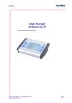
iOS
Android
Default access code is "1111".
Structure of the smart voice menu
Online Data Unit
System Information
7
Information about vehicle state
Trigger log
Event log
List of deactivated features and functions
Task manager contents
Help
Quickly provides online critical
information about the state
of the Alarm and the vehicle.
The unit contents can be changed.
Control Commands
8
1 2 3
4 5 6
7 8 9
Commands to control the Alarm
Activation and extra channels
Checking account balance etc.
Help
Quick Access Commands
These commands can be customized.
System Information
Control Commands
Settings
Help
General information about the system
TEC-61231-22 Technical Manualе PRIZRAK
9
Settings
Task manager
Remote launches and optional channels
Sensors
Online data unit
Quick access commands
Users and access permissions
Notification settings
Advanced settings
Help
3
Alarm operation algorithms
Arming/disarming
o arm the alarm press the lock button of the remote, or close the
T
doors with keyless system or lock the door with the key. Alarm will
warn you that it is armed with audible signal and LED flashes. After
some time interval between flashes will decrease.
To disarm the alarm press unlock button of the remote, or open
vehicle with keyless system. Alarm will warn you with 2 audible signals.
LED will go off.
Arming and disarming can be done by the voice menu or the
mobile application
Warning about open door
If you left an open door, hood or trunk and armed the Alarm, the
system will warn you with 3 audible signals. LED will inform you about
open compartment:
• Two – the hood is open
• Three – the trunk is open
• Four – the door is open.
The Alarm cannot monitor entry through unlocked door. It is
possible to close the doors (hood, trunk) while still in Security
mode, then the Alarm will automatically continue monitoring
Triggering the Alarm
The alarm has 2 built-in sensors: shock sensor and tilt/movement
sensor. Because of these sensors the alarm is able to differentiate
different influences on the vehicle. Optional sensor can be connected
if required. The alarm can be connected to multiplex sensors and
standard sensors.
In secure state alarm can react to external action by warning or
by triggering. Warning will be made if small force was applied to the
shock sensor. In this case alarm will make short audio signals.
Alarm will be triggered, if any door, hood, or trunk is open, if tilt/
movement sensor is triggered, and if excessive force was applied to
the shock sensor. Siren will be on for 30 seconds and hazard lights
will blink.
You can adjust sensors sensitivity.
Function of protecting public order
After three triggers in armed mode from one sensor in one hour
alarm will stop responding to this sensor for one hour. Alarm will
continue working with this sensor if there were no triggers for one
hour. This function will cancel alerts but warnings will stay
Trigger check
Alarm remembers causes of alerts for security period. Memory will
be cleared after ignition switched on.
If alarm was triggered, after disarming the alarm four audible
signals will be made and indcation of cause will start (check table 1).
Table 1. Trigger indication
LED flashes
Note
x1
Public order feature
x2
Hood was opened
x3
Trunk was opened
x4
Door(s) was (were) opened
x5
Triggering of the shock sensor (alarm)
x6
Triggering of the shock sensor (warning)
x7
Triggering of the tilt/displacement sensor
x8
Triggering of an extra sensor (alarm)
x9
Triggering of an extra sensor (warning)
Detailed information about events can be found in the trigger log which can be accessed from the voice menu.
Arming with sensor deactivation
There are situations when you need to arm the Alarm with sensor
input deactivation.
To deactivate sensors:
• Arm the alarm
• Press the remote control button for 3 seconds. The siren will
emit one long intermittent sound, then a short sound after a
pause. Now the warning is off. The Alarm will not respond to
mild impact to the vehicle
• Within the next 3 seconds press the remote control button
again: the siren will emit one long intermittent sound, then two
more signals after a pause. Now all sensors are deactivated.
Trunk opening without leaving the security mode
You can open the trunk with remote or keyless system. While
trunkis open alarm will stop reacting to sensor input, but will control
doors so the vehicle will stay secured from intrusion. After trunk is
closed, the system will secure it and turn all sensors back on.
Hands-free function
When the engine was started remotely, hands-free function
will check that the RFID tag is within the coverage. The Alarm will
automatically unlock the vehicle upon owners approach, and will lock
it back when owner left the vehicle.
RFID check when disarming
In this mode when you unlock the vehicle via remote control or
keyless access system, the Alarm will search for the RFID tag. Only
after the RFID tag is detected, the vehicle will be disarmed.
The RFID tag is looked for only if the Alarm was armed for
more than 30 seconds. While searching the system will emit
intermittent sound. If you don’t have the RFID tag with you,
then within 10 seconds after a door, hood or trunk is opened,
an alarm will go off. To deactivate the alarm signal, turn on the
ignition and authenticate yourself.
Factory remote door lock control
This function does not allow opening doors by using signal imitation
equipment, and also will lock access into vehicle in case if the remote
was stolen (if electromechanical locks were installed).
After receiving a signal to open from the factory remote, the alarm
will search for RFID tag, and only after authentication, doors will open.
Feature can operate permanently – RFID tag will be required every
disarming of the alarm, and temporary in places where you need
maximum safety(see. Quick engaging of the second circuit for higher
risk locations). Toggling and selection of the operational mode is done
in the alarm hardware features menu.
There are three methods to use this feature. Each method can be used on its own or together with other methods:
4
TEC-61231-22 Technical Manualе PRIZRAK
Installing electromechanical door locks
Electromechanical
locks
are
controlled
with
"Close
electromechanical door locks" and "Open electromechanical door
locks” outputs. Pulse to close locks will be formed after arming the
alarm (condition being: doors, trunk and hood are closed). Pulse
to open – after receiving signal from factory remote and RFID
authentication.
CAN bus lock
No additional connections required. For support of a specific
vehicle check "Integrator".
Commutation of central lock control circuits, with
output "Control of central lock normally open relay"
Signal is formed on the output after receiving signal from factory
remote and RFID authentication, and stays until alarm is armed. Signal
is constantly present (if CAN bus is active), if maintenance mode is
active or PIN Code authentication was chosen.
If the vehicle is opened by phone, RFID tag is not required.
Immobilizer feature
Immobilizer is a feature designed to prevent vehicle from being
stolen from parking space. PIN TO Drive® goes into effect if ignition
was switched off for more than 3 seconds. If PIN TO Drive® feature is
enabled and active it requires PIN code to be deactivated, otherwise
engine will be locked:
•
•
Engine will be switched off on attempt to move if speed control
is enabled and supported by the vehicle
The engine will be turned off within 5 seconds after the
ignition has been turned on if the Speed control is disabled or
not supported by the vehicle.
AntiHiJack feature
AntiHiJack is the function that prevents the vehicle from being
hijacked or stolen from the parking area. AntiHiJack enters the Guard
mode in the following cases:
• The ignition was turned off for longer than 3 seconds
(including a case when Immobilizer is off; if the Immobilizer
was switched on, the Alarm will follow its algorithms)
• The driver’s door was opened.
Upon entering the Guard mode, AntiHiJack feature goes through a
series of phases, and in case if the Guard mode was not deactivated,
the feature will activate the engine lock.
Phases change only when the ignition is on. When the ignition
has been turned off, the Alarm saves the current condition, and will
continue the feature operation when the ignition is back on.
The Guard mode of the AntiHiJack feature can be deactivated at
any step by entering the PIN code.
The Guard mode phases are as follows:
• Idle phase
• Warning phase
• Locking phase
Idle phase. In this phase AntiHiJack follows two different algorithms
depending on the availability of Speed control. If the Speed control
is available, AntiHiJack waits until the vehicle covers a set distance
from the moment of Guard mode activation Upon that, AntiHiJack
goes into the Warning phase. If the Speed
control is not available, Idle phase consists of three stages:
• Waiting for the driver’s door to be closed
• Waiting for preset amount of brake presses to be made
• Pause before going to warning phase.
Warning phase consists of two steps:
• Warning the driver with the trill that they have to enter PIN
code.
• Warning other drivers on the road of the possible hazardous
situation due to the upcoming engine locking (10 seconds). It
is carried out by vehicle hazard lights. Driver warning is still on.
Locking phase. The engine lock is activated, the siren is turned
on, and the hazard lights are activated. The siren and hazard lights
will switch off in 15 seconds. AntiHiJack will be in locking phase until a
new PIN code verification.
If "Safe stop" is enabled engine will be locked only if speed is
lower then 30 km/h or on complete stop (depends on the
settings of the safe stop).
The safe locking option reduces probablity of accidents when the
Engine Lock feature is used.
When the ignition is off, AntiHiJack turns off the hazard lights and
audio warning signals for the driver. If the Immobilizer feature has
not entered the Guard mode (see the Immobilizer feature section)
then, upon the next ignition, AntiHiJack will do an audio warning for
the driver and switch on hazard lights for 15 seconds. AntiHiJack will
not prevent the ignition but will interfere with driving as per the same
algorithms as the Immobilizer feature.
If Immobilizer is in the Guard mode, then when the ignition
switched off, AntiHiJack will be deactivated, and the Alarm will follow
algorithms of the Immobilizer feature.
Accelerator pedal lock (force to stop)
Feature will stop the vehicle if AntiHiJack was triggered minding
activate for 2 seconds, then it will be lifted for 5 seconds. This will be
safe lock settings. Vehicle has to support "speed control". At the repeated 5 times. Every repetition lock lift will be reduced for 1
eng of the warning phase, if speed of the vehicel didn’t increase within second. On fifth repetition lock will be permanent.
5 seconds or brake pedal was pressed within 3 seconds, lock will
TEC-61231-22 Technical Manualе PRIZRAK
5
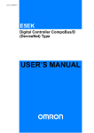
RFID tag
RFID tag is an electronic key that must be with the driver at all times during the vehicle operation. Before the vehicle starts moving, the
system will automatically identify the RFID tag and deactivate all security functions. When the RFID tag is identified, the system will emit a trill.
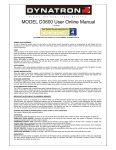
Battery replacement
If the battery needs to be replaced, the system will trigger 5 short audio signals after the RFID tag is identified. The battery type for the
RFID tag is CR 2025. To replace it, contact the system installer or do it yourself.
Carefully
observe the
polarity
Open here
3V
CR 2025
To easily open the tag, you can
use an edge of a plastic card
Use only high quality nonexpired batteries!
If the ambient temperature is below zero, batteries can perform worse due to slower rate of chemical reaction. It can make identification
of the RFID tag more difficult, especially if it was exposed to low temperature environment for a long time. To restore performance
of the battery just warm up the RFID tag.
Dual authentication
Authentication locates and identifies the RFID tag and/or entered PIN code. This procedure is carried out when the ignition is on or the
engine is started. After successful verification, LED will be switched off and a trill is emitted.
Method of authentication
RFID tag (factory default)
PIN code*
RFID tag or PIN code
RFID tag and PIN code
(dual authenication)
Table 2. Methods of authentication
Verification procedure
RFID tag is with you
Enter PIN code
RFID tag is with you
RFID tag is not available. Enter PIN code
Wait for a trill.
LED will go out
RFID tag is with you. Enter PIN code
Wait for two trills.
LED will go out.
If you use the RFID tag and PIN code authentication, both security circuits have to be deactivated before the vehicle starts moving.
If one or more circuits are still active (i.e. there is no RFID tag, or PIN code is not entered), the vehicle will not move.
Authentication method can be selected when installing the Alarm without using the PUK code. As a result, the PUK code remains
secret.
Authentication method can be changed without using the PUK code if:
• The vehicle did not travel more than 10 km after the Alarm was installed (the Speed control is available)
• The ignition was not active for more than 20 minutes after the Alarm was installed (the Speed control is not available).
If during the installation the verification method was switched to "RFID tag or PIN code" after the vehicle was driven for 10 kilometers (if the
Speed control is unavailable: after the ignition was on for 20 minutes) at the end of each verification an alarm signal will sound. It will inform
that verification method was changed. To deactivate the signal, enter the PIN code.
Quick engaging of the second circuit for high risk locations
The RFID tag authentication is very easy to use. In most cases this
verification method is enough to protect the vehicle. However, when
leaving the vehicle in high risk locations (for example, at public parking
lots) you can provide maximum hijack protection by engaging second
circuit for one security cycle. Authentification method can be quickly
changed from "RFID tag or PIN code" to "RFID tag and PIN code"
without need to use the settings menu.
6
To quickly engage maximum security:
• Turn on the ignition
• Wait for RFID identification
In the next 10 seconds:
• Open and then close the driver’s door
• Enter the PIN code, wait for confirmation
• Turn off the ignition
• Wait for two trills which mean that "RFID tag and PIN code"
verification method is activated.
TEC-61231-22 Technical Manualе PRIZRAK
PIN code
PIN code is a secret combination of presses on one or more
original buttons in the vehicle. Please refer to the Integrator files for the
list of original buttons that can be recognized by the system in a specific
vehicle. PIN code is entered before driving the vehicle.
PIN code is a one-, two-, three- or four-digit number.
PIN code can be easily changed many times by both technical
specialists during installation of the system or by user during day-today use of the vehicle.
To ensure a proper security level, the factory default PIN code
should be changed. If you don’t do it, an alarm will sound after
entering the PIN code, which reminds you to change the PIN code.
The factory default PIN code is "2"; it is entered by using the Programming button (please see the Integrator).
Entering the PIN code
PIN code is entered with the ignition (or engine) turned on by pressing original buttons. When entering one of the PIN digits, please make
sure that pressing time or pause are no longer than 1 second. Please keep a pause of approximately 2 seconds in between digits. If you made
a mistake while entering the PIN code, a warning will sound in about 3 seconds, then you can re-enter the PIN code.
PIN code entry sequence
•
•
Turn on the ignition or start the engine
Enter PIN code
Buttons
,
,
,
,
•
Wait for the confirming trill.
Available PIN options
are used here as an example. Request the list of avaliable buttons in your vehicle at your shop.
One-digit PIN:
Two-digit PIN:
~2 second pause
Single-button PIN entry
When entering the PIN code keep in mind the entering sequence.
One-digit PIN:
Two-digit PIN:
~2 second pause
PUK code
PUK code is required if:
• You have lost the RFID tag or lost/forgot the PIN code
• You want to change identity verification method.
After PUK code is entered, all security functions of the Alarm will
be deactivated regardless the selected authentication method. PUK
code can be found under the scratch layer on the plastic card.
The factory set PIN code is "2"; it is entered by using the Programming button (please check the Integrator).
PUK-code entry
PUK code is entered by the Programming button with a 2 second pause in between keystrokes.
Entering sequence:
• Enter PUK code
• Turn on the ignition or start the engine
• Wait for the confirming trill.
Maintenance mode
Maintenance is an operation mode when all hijack protection and
service functions of the Alarm are temporarily disabled.
The Alarm will notify of activation of the Maintenance mode as
follows:
• When disarming, LED will turn on
• When the ignition is turned on, LED will go out
• After identity verification an alarm will sound
• After the ignition is turned off, LED will light up and will be on
for a while.
To
steps:
1.
2.
3.
activate or deactivate the Maintenance mode follow these
Turn off the ignition.
Follow through with identity verification.
Press the Programming button 6 times (you should start within
10 seconds after verification).
4. Wait for confirmation of your actions:
• If the Maintenance mode is on, the system will emit 1
audio signal, 1 light signal and a trill
• If the Maintenance mode is off, the system will emit 2
audio signals, 2 light signals and a trill.
Automatic deactivation of the Maintenance mode
This function automatically disables the Maintenance mode after
a 10 km run. So even if you forget to disable this mode in the service
station, it will still be automatically disabled.
If Maintenance mode is activated by PUK code, it cannot be
automatically disabled.
TEC-61231-22 Technical Manualе PRIZRAK
If the vehicle does not support Speed control, automatic
deactivation of this feature will not be avaliable.
7
Warning signals after authentication
Additional sound signals after verification usually call for certain actions.
Table 3. Warning signals after authentication
Warning signal
Long audio
signal
Five short audio signals
Source of a signal
Actions to take
The default PIN code was not changed
Change the default PIN code
The maintenance mode is on
Disable the Maintenance mode
When installing the system, verification method
was switched to "RFID tag or PIN code"
Enter PIN code
(this confirms that verification method was
changed)
Battery in the RFID tag should be replaced
Replace RFID tag battery
Other options
The system has several options to make your vehicle more comfortable and secure.
Geolocation of the vehicle
Central lock control
The system can show the vehicle position on the map at any moment. It If your vehicle does not have an integrated door lock activated when
requires installation of a GPS/GLONASS-270 unit. To locate the vehicle, you driving (locking) or turning off the ignition (unlocking), this option can
need to send a text message command or via voice menu or using your be provided by the Alarm system.
mobile application.
Microphone
Automatic window roll up
A microphone provided with the Alarm system enables the driver
The system can be programmed so that the vehicle windows are at any point to hear sounds inside the vehicle or in the vicinity. This
rolled up when engaging the lock.
requires only one call to the Alarm system.
Setting the electromechanical hood lock
Optional parking system control
You can install an additional hood lock and program the Alarm to The Alarm system has flexible algorithms to control additional parking
lock the hood when locking the vehicle, and open it only after identity sensors. There are three control modes available, and the system can
verification.
be controlled by using original buttons in the vehicle.
8
TEC-61231-22 Technical Manualе PRIZRAK
Connection
Inputs/outputs of the Alarm
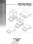
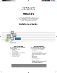
Inputs/outputs of the Alarm are described in the following tables. Contact numbers are shown in Fig. 1. Configuration of inputs/outputs is programmed
(see Programming the Alarm hardware features).
2
18
10 8
1
9
1
4
5 4
3
2
1
Fig. 1. Numbers of port connector pins from wiring viewpoint
Table 4. Description of the systems main (18-pin) connector
Connector
#
Color
Type
Note
18-pin
1
2
3
4
5
6
7
8
9
10
11
12
13
14
15
16
17
18
–
Blue/Yellow
Brown
Brown
Pink/Green
White/Black
Gray/Black
Yellow/Red
Black
–
–
Brown/Yellow
Brown/Red
Green/Black
Blue/Red
Gray/Yellow
Pink/Black
Red
Ground
–
CAN 2
CAN 1
(+) programmable input
(-) output
(-) programmable input
Data link
Ground
+12 V
–
CAN 2
CAN 1
(-) programmable input
(+/-) programmable output
(+) programmable input
(+/-) output
+12 V
Power for additional devices (TP-BUS)
Heater WBUS(Webasto, Ebersacher)
CAN2-L bus
CAN1-L bus
Stop signal control
Wired engine lock
Reference ground/Negative button
Connection between main unit and lock relay
Power
Power for additional devices (TP-BUS)
TP-BUS (control bus for additional devices)
CAN2-H bus
CAN1-H bus
Hood position control
Turn signals alternate control
Analog buttons/Positive button
Siren control(+)/Horn control(-)
Power supply
1
2
3
4
5
6
Orange/Green
Orange/White
Yellow
Black
Yellow/White
Green/White
(–) Programmable input
(+) Programmable input
(+) microphone
(–) microphone
(–) Programmable output
(–) Programmable output
7
Green
(–) Programmable output
8
Blue
(–) Programmable output
Engine shutdown in remote start
Disable alert if trunk is open
Microphone
Microphone
Front parking sensors control
Rear parking sensors control
Impulse to close the hood/Alternate Central
Lock control (Lock for twin-wire control. Lock/
Unlock for one-wire central lock control)
Authentication pulse/Alternate Central Lock
control (Unlock for twin-wire Central Lock
control)
1
Red/White
Power supply
+12 V power supply for Fortin or iDatalink
unit
2
Black/Yellow
Power supply
Ground for Fortin or iDatalink unit
3
Gray/Blue
DATA(RX) connect to the
blue wire (Fortin) or black/
white (iDatalink) wire
Control of a Fortin or iDatalink unit
4
Gray/Green
DATA(TX) connect to the
white wire (Fortin) or
black/white (iDatalink)
wire
Control of a Fortin or iDatalink unit
1
2
Red
Blue
(+) output
(–) output
+12 V power supply
Ground
8-pin
4-pin
2-pin(LED)
Current, mA
–
–
–
–
1,5
150
0,5
–
–
–
–
–
–
1,5
±150
0,5
1,300/150
1,500/10*
1,5
1,5
–
–
150
150
150
150
*Given is the average current value in operating and idle modes. It is subject to change according to positive outputs demand.
Useful current of output #9 depends on demand connected to negative outputs.
Outputs #6, 15, and 17 are protected from short-circuit, inductive eruptions, overheating, and overload.
TEC-61231-22 Technical Manualе PRIZRAK
9
Description of pins in the Alarm main port
Pins #1, 10, 11. Used only for additional (optional) modules
connected via TP-BUS (such as HCU-230 hood module, ESM-250
remotestart module, etc.).
Pin #2. Heater control (Webasto, Eberspacher)
Pins #3, 12. CAN2 vehicle data bus. Connected in particular cases
(please see the Integrator files).
Pins #4, 13. CAN-L, CAN-H vehicle data buses. Connected to the
vehicle CAN bus (please see the Integrator files).
Pin #5. Brake lights state. Used if the vehicle CAN bus does not
contain brake pedal position data (please see the Integrator files). In
such cases Pin #5 is connected to the output of brake pedal terminal
switch.
Pin #6. Engine lock. Connected to one of the relay coil contacts,
which is used to lock or startup the engine.
Pin #7. Reference ground/Negative button. Subject to selected type
of a control button, one of the following functions is used:
• Reference ground: when an analog control button is selected,
pin is connected to the appropriate wire of the vehicle (please
see the Integrator files)
• Negative button: is connected to the negative (controlled by
making contact with the ground) button. It is used when there
are no original buttons recognized by the Alarm.
If the vehicle has original buttons operated via CAN bus and
recognized by the Alarm, this input can be vacant.
Pin #8. Data. Connects to positive terminal of switched or nonswitched circuit. +12 V signal has to be present when the engine is
running. This connection is used to connect lock relay and the main
unit
Pin #9. Ground. Connected to the vehicle body via connection point
designated by the vehicle’s manufacturer for ground connections with
factory equipment.
Pin #14. Hood position state. Used only when the vehicle CAN bus
lacks information about hood position.
Pin #15. (+/-) output. Alternative hazard lights control. Controls
hazard lights for the vehicles where CAN bus is not used. For more
details on how to use it in a specific vehicle please refer to the
Integrator.
Pin #16. Analog button/Positive button.
Subject to selected type of a control button, one of the following
functions is used:
• Analog button is connected to the relevant wire of the vehicle
at the steering wheel "helix" port (please see the Integrator
files)
• Positive button is connected to the positive button (controlled
by +12V voltage). Used when original buttons are not
recognized by the Alarm.
If there are available original CAN buttons, and they are recognized
by the Alarm, this input can be left unused.
Pin #17. Siren control/Horn control. Appropriate algorithm is set
when the Alarm is installed (see Programming the Alarm hardware
features).
Pin #18. Power supply of the Alarm. Connected via 3A fuse to one of
the non-switched +12 V circuits.
Do not connect Data output to the cigarette lighter circuit.
pLine-221 description and installation guidelines
Table 5. Relay outputs description
Color
Type
Note
Current
Red
Black
Yellow
Yellow/Red
Yellow/Black (Yellow/White)
Communication and power
Power source
Common contact
Normally closed contact
Normally open contact
+12 V
"Ground"
Lock output
Lock output
Lock output
1 А/10 mА*
—
10 А
10 А
10 А**
* While transmitting data (pulses) up to 1 A. When receiving data up to 10 mA ** Limited by cross section of the wire.
"Communication and power" has to be connected to the positive
switched circuit of the vehicle. This circuit has to be enabled if the
Ignition is enabled (for example: ignition, injectors, ignition coils).
You may lock any circuit in the vehicle.
After installation it is recommecned to check link between relay
and Alarm.
Relay has a built-in accelerometer for vehicles that have no
information about speed in the CANbus, and enables extra features
for vehicles that have information about speed present in the CANbus:
• Lock the engine even if there is no speed information in the
CAN bus
•
•
•
•
Accelerometer allows starting the engine and locking it if the
vehicle began movement.
It is not recommended to install the relay in places that vibrate
heavily during engine starting or launching. This can prevent movement
detecton due to excessive noise passed to accelerometer.
Factory default sensitivity settings mean that there are almost no
vibrations transfered from the engine.
After installing the alarm it is recommended to check sensitivity
settings and adjust them if required.
You may install only one pLine-221 relay in the vehicle.
Relay works as normally locked relay.
If same circuit that is used for connection with the alarm is locked, "Communication and power" has to be connected higher than
lock point.
CAN bus parameters indication
Geature shown following parameters:
• Hood, trunk, doors (each door individually)
• Ignition switch state (key presence, АСС, IGN, Start)
• Engine is running
• Gearbox state (for automatic – P, R, N, D; for manual – R)
• Parking brake
• Stop-signal
• Security
• Factory security system alert
• Central lock state
• Sensors ignore
• Engine RPM
• Engine temperature
10
Feature allow quickly check vehicle state and adjust connection
if required. Buit-ib LED is used for indication (check "Connection
scheme"). LED lights up if any parameter is selected and stays for 5
seconds or until other parameter is chosen.
"Engine RPM" and "Engine temperature" will be indicated if no
other parameters are chosen:
"Engine RPM" — LED flashes with frequency proportional to the RPM:
1 flash per second equals 500 RPM of the engine.
"Engine temperature" — LED flashes 1 time every time new data
received (with ignition or or the engine running).
TEC-61231-22 Technical Manualе PRIZRAK
Programming – Stage one
The Alarm is programmed by using the Programming button.
Identifying the vehicle model
Vehicles supported by the system are divided into groups, each of
Programming sequence:
which is divided into subgroups. All groups and subgroups are assigned
1. Power the Alarm, wait for an intermittent sound.
with a number (see the Integrator). Identification is the procedure of
2. Enter "Menu 1": press and release the Programming button 10
detecting group and subgroup of the vehicle by the system.
times (this has to be done within 10 seconds after the system
There are two ways to identify the vehicle:
has been powered). If all actions were performed correctly, the
1. Automatic identification.
Alarm will make three audio signals.
After connecting with the vehicle CAN bus, supplying power,
3. Enter Menu option 1 (Vehicle model) by pressing the
and performing a few simple actions (for most vehicles those are
Programming button once. The Alarm will notify of the selection
the ignition on/off and close/open the cenral lock via original remote
of this option by repeating single audio signal.
control) group and subgroup will be detected automatically. The user
4. Enter the vehicle group number by pressing the Programming
verifies identified group and subgroup by listening to the sound signals
button corresponding number of times (see the Integrator).
(group number – pause, subgroup number – pause).
5. Enter the vehicle subgroup number by pressing the
Identification procedure for all supported vehicles can be found in
Programming button a relevant number of times (please see
the Integrator.
the Integrator files).
If the group number is a two-digit number, enter the first
If the group number is a two-digit number, each digit will be
digit, wait for 2 seconds, and then enter the second digit. The
identified individually. For example, group 35 and subgroup 2
Alarm system will emit a sequence of audio signals indicating
will produce the following sequence of sound signals:
the group number.
3 long signals – pause (1 sec), 5 long signals – pause (2 sec),
2 short signals – pause (4 sec), etc.
2. Forced interfacing.
By listening to audio signals, verify that the vehicle model was
This is used in extraordinary cases. Programming is carried out selected correctly:
with the integrated button. Before interfacing the vehicle group must
• If the model was selected correctly, press the Programming
not be identified and the CAN bus must not be connected. The Alarm
button once. Signal sequence will stop, and the vehicle model
will leave the programming mode if the Programming button is not
will be saved
pressed for longer than 60 seconds.
• If the vehicle was identified incorrectly, press the Programming
button twice. Repeat programming starting from step 4.
Analog steering wheel buttons programming
To program analog steering wheel buttons:
3. Turn the ignition off; a trill will sound
1. Right after the Alarm identifies the model, turn the ignition on
4. Turn the ignition on
and wait for at least 5 seconds
5. To assign the Programming button from available buttons,
2. Press all the steering wheel and steering wheel column joysticks
push it and hold for at least 5 seconds (until you hear an audio
buttons (cruise control, central unit control, etc.) sequentially
signal).
(one after another). Sound after button press means that this
button was recognized.
Digital button programming
To use digital button (positive and/or negative):
• Assign activated button as the Programming button: turn the
• Set the Alarm to operate with digital buttons (Menu 1. Option
ignition on, push the button and hold it for at least 5 seconds
4) note that this menu option can be modified only by using
(until you hear an audio signal).
a built in button and before the PIN code was entered for
Button have to be programmed within 15 minutes after
the first time via using analog or digital buttons. Any further
interfacing the Alarm. If these 15 minutes have passed,
modifications will possible only after system reset)
initiate the reset sequence, and perform programming steps
again.
Connection check between main unit and relay
1. Turn the ignition on.
• Changing the operating modes of heating systems (seat heater
2. Enter PIN code, wait for confirmation.
in different power modes, window and mirror heating)
3. Press and release the Programming button 10 times (this has
• Changing the operating modes of lighting (low beam, marker
to be done within 10 seconds after entering the PIN code). The
lights, fog lights).
Alarm will confirm menu entry with three audio signals.
Special attention should be paid to communication testing for high
4. Choose Menu 1 option 19 by pressing and releasing the engine rpm. The engine speed should be changed very smoothly, while
Programming button 19 times. The Alarm will notify of this constantly monitoring the system. Communication errors can occur in a
option by a sequence of 19 audio signals.
very narrow range of the engine rpm. ОIsolated communication errors
5. Push brake pedal and hold for at least 10 seconds. After the (occasional short-term jams, indicated by variable two-tone signals)
Menu option has been accessed, the system will indicate it are allowed. If under any condition communication errors are frequent
audibly (if the communication has been established – short (dual-tone signal is on for longer than 2 seconds), choose another
two-tone signals each 0.5 second; no communication – steady connection circuit, since tested connection does not guarantee a failtwo-tone signal).
safe operation of the system.
Operation of all main systems of the vehicle should be tested in all
To exit this Menu item, tap the brake pedal. To exit the programming
available modes (ideally, the system operation should be checked with mode, turn the ignition off.
various combinations of electric equipment):
Any pLine-221 relay (even priviously installed on another
• Turn the on climate control in various modes
vehicle with a different main unit) can be used for
• Changing the speed of the heater fan
communication testing, but the Alarm will function only with
a pLine-221 relay tied with a specific main unit.
Accelerometer sensitivity adjustment
1. Turn the ignition on.
5. Start the engine and check sensitivity in the range within idle
2. Enter PIN code, wait for confirmation.
- 2000 RPM). If lock triggers immediately after accelerometer
3. Press and release the Programming button 10 times (this has
press, reduce sensitivity by pressing button 1 time. Start the
to be done within 10 seconds after entering the PIN code). The
engine at lest 3 times to be sure that lock will not happen.
Alarm will confirm menu entry with three audio signals.
After starting the engine let it run for at least 10 seconds.
6. Choose Menu 1 option 20 by pressing and releasing the
Programming button 20 times. The Alarm will notify of this
option by a sequence of 20 audio signals.
To leave the programming mode turn off the ignition and wait for
4. Depress brake pedal and hold it for more than 10 seconds. The at least 3 seconds.
alarm will indicate current sensitivity settings (factory default
"1" — maximum sensitivity).
TEC-61231-22 Technical Manualе PRIZRAK
11
Programming – Stage two
Programming the Alarm configuration
At stage two the Alarm hardware functions and user settings are changed, and a new PIN code is programmed.
Table 6. Programming menu
Menu code
Number of
audio signals
10
3
Configuration of the Alarm hardware settings
11
6
Configuration of programmable inputs/outputs
12
4
Configuration of the user settings
8
5
Remote start configuration
16
7
Adjustment of sensitivity of additional shock sensor; switching on/off
the tilt/displacement sensor
Menu is active only with ESM module installed or with remote start
digital output active
Heater configuration
17
8
Configuration of heater operating modes
Name of the menu
Hardware features
configuration (Menu 1)
Configuration of
programmable inputs/outputs
(Menu 1.1)
User functions configuration
(Menu 2)
Set up shock sensors and tilt\
movement sensor
Designation
Programming the Alarm hardware
The Alarm is programmed in accordance with "Hardware features configuration" table.
Table 7. Hardware features configuration
Range
Factory default
settings
–
–
Engine lock
1-4
2
3
Safe lock
1-3
1
4
Type of external buttons
1-2
–
5
Control of the factory
security system
1-2
On
6
Sequential door opening
1-2
Off
7
Hazard lights control algorithm
1-5
–
8
Central lock alternative
control algorithm
1-3
–
9
Siren control/Horn control
1-2
1
10
Time interval of Timer
Channel (Comfort) feature
1-6
3
One unit equals 10 seconds.
11
External sensors multiplex mode
1-2
1
12
Engine start lock
1-2
2
13
Parking system control
algorithm (activation)
1-3
1
14
Parking system control button
–
–
15
Speed control
1-2
1
1 – multiplex operating mode of external sensors
2 – standard operating mode of external sensors
1 – on
2 – off
1 – by reverse gear; 2 – by speed;
3 – by reverse gear with an override
It is possible to assign CAN bus recognized button,
analog button or digital button (positive/negative)
1 – on
2 – off
16
Brake presses
1-7
3
–
17
GSM lock
1-2
2
1 – on (GSM interlock disabled)
2 – off (GSM interlock enabled)
18
Car battery warning threshold
1-15
8 (11,3)
19
20
–
–
–
–
–
–
21
RFID tag
1-4
1
#
Option
1
Vehicle model
2
12
Notes
–
1 – control of a normally open relay;
2 – control of a normally closed relay;
3 – acceletator pedal lock (force to stop);
4 – starter motor lock
1 – Engine will be locked regardless of speed;
2 – if speed is 30km\h or lower;
3 – on complete stop
1 – analogue buttons; 2 – digital buttons.
Inputs #7 and #16 (connector Х1,18-pin)
1 – on
2 – off
1 – on
2 – off
1 – pulse negative; 2 – status negative;
3 – pulse positive; 4 – status positive;
5 – lights control (negative)
1 – single wire pulse negative; 2 – single wire pulse negative
(if central lock state if unavaliable);
3 – two wire pulse negative
Selecting operating mode and polarity of output #17.
1 – Siren control. Emitting of a constant level signal (+12V).
2 – Horn control. Emitting of an intermittent negative
signal. Controls the original horn of the vehicle
1 – 10.6 V … 15 – 12 V
–
–
1 – not in use; 2 – RFID check when disarming; 3 – factory
remote lock; 4 – factory remote lock in high risk locations
TEC-61231-22 Technical Manualе PRIZRAK
22
Fuel tank volume
1-30
1
Used to convert fuel level from percent to liters.
1 – not defined. Fuel is measured in percent
2 - 10 liters..30-150 liters. Step is five liters
23
Alert delay if perimeter
was breached
1-5
1
1 - disabled; 2 - 0.5s; 3 - 1.0-s; 4 - 2.0s; 5 - 3.0s;
24
Engine lock via CAN
1-2
2
1 - enabled; 2 - disabled. If feature is enabled and
supported by the vehicle(check Integrator) - engine can
be locked via CAN bus (without additional connections)
25
Perimeter control pause(30s)
1-2
2
1 - on; 2 - off;
26
Beach mode
–
-
–
27
Immobilizer bypass unit
1-2
-
Set automatically. 1 - Fortin; 2 - iDatalink;
Option #13. "Parking system operation algorithm":
• "Activation by reverse gear". Front and rear parking sensors are
switched on when gearbox is in R position or by using a control
button. They are switched off when the speed exceeds 15 km/h
or by using the parking system control button
• "Activation by speed". Front parking sensors are switched on if
the vehicle speed is under 15 km/h. Rear parking sensors are
switched on if the vehicle moves backwards with a speed under 15 km/h.
In this mode all parking sensors can be disabled by using a control
button until the next ignition sequence or command from a control
button
• "Activation by reverse gear with a shutdown override". Here
algorithm is similar to "Activation by reverse gear". However, when
parking sensors are disabled by using a control button, they will not
be activated when gearbox is in R position up to the next ignition or
command from a control button.
Table 8. Configuration of programmable configuration of inputs/outputs
Setting range
Factory
default settings
1-41/Alternate hazard lights control
Hazard lights alternate control
Polarity of output #15
1-2
Negative polarity
3
(–) output #5
(8-pin port)
1-41
17
4
(–) output #6
(8-pin port)
1-41
18
(–) output #7
(8-pin port)
1-41
25/alter. Central Lock
(–) output #8
(8-pin port)
1-41
4/alter. Central Lock
7
(–) input #1
(8-pin port)
1-24
12
8
(+) input #2
(8-pin port)
1-24
7
1-24
1
(-) input #7
(18-pin port)
1-24
–
(-) input #14
(18-pin port)
1-24
2
(+) input #16
(18-pin port)
1-24
–
#
1
2
5
6
Connector
X1
18-pin
X2
8-pin
11
12
(+/–) output #15
(18-pin port)
(+) input #5
(18-pin port)
9
10
Function
X1
18-pin
Options 1, 3-6. Designed to customize the Alarm outputs by
assigning a function to a specific output (see "Programmable output
functions" table).
Option 2. Defines the polarity of the Alarm output #17.
The polarity can be defined only if this output is assigned one of
the functions (see "Programmable output functions").
TEC-61231-22 Technical Manualе PRIZRAK
Option 5 Arming pulse or lock Central Lock/lock/unlock Central
Lock
Option 6 Identity verification pulse or unlock Central Lock
Options 7, 12 To be able to program this pin “Digital buttons”
option has to be chosen
Options 7-14. Designed to customize the Alarm inputs by assigning
a function to a specific input (see "Programmable input functions"
table).
13
Table 9. Functions of programmable outputs
#
Function
Description
1
Security state
Emitting a constant level signal while the Alarm is in Security mode
2
Arming pulse
Emitting 0.8 sec pulse when entering the Security mode or triggering AntiHiJack feature.
3
Disarming pulse
Emitting 0.8 sec pulse when leaving the Security mode.
4
Authentication pulse
Emitting 0.8 sec pulse after PIN code is entered or in Maintenance mode (1 second after the ignition has
been turned on).
5
Factory alarm panic
Emitting of a constant level signal while the original alarm system (if installed) is in alarm condition.
6
Beeper panic
7
Horn panic
8
Doors, hood and trunk
Emitting a constant level signal if any of the preset doors, hood or trunk is triggered.
9
Sensor ignore
Emitting a constant level signal in the Security mode if the trunk is opened via original remote control. The
signal is also emitted for the purposes of Comfort feature. This function can disable sensors to prevent false
alarms.
10
Factory buttons
Emitting a constant level signal when pressing a preset button of the vehicle.
11
Ignition
Emitting a constant level signal when the ignition is turned on (including the engine startup).
12
АСС
Emitting a constant level signal when ACCs of the vehicle (1st key position; for some vehicles it matches the
ignition position) are on. The signal stops only after the key is out of the ignition lock. This function can help
to correctly manage power supply to an accessory alarm system of multimedia system.
13
Engine is running
Emitting a constant level signal when the engine is on.
14
Engine RPM
15
Gearbox state
16
Vehicle is moving
Emitting an pulse with a pulse frequency in proportion with the engine crankshaft rpm. 1 pulse per second
corresponds with 20 rpm of the crankshaft. The signal helps to evaluate the rpm rather than give an exact
value.
Emitting a constant level signal if transmission handle is in preset position (P, R, N, D1)). For semi-automatic
transmission positions R, N, D 1); for manual transmission only position R.
Emitting a constant level signal if the speed exceeds some threshold value (the speed value is different for
each vehicle, but generally it is in the range of 5 to 10 km/h).
17
Front parking sensors control
Emitting a constant signal level in accordance with the preset algorithm of the parking system.
18
Rear parking sensors control
Emitting a constant signal level in accordance with the preset algorithm of the parking system.
19
Movement speed
Emitting a pulse with a pulse frequency in proportion with the vehicle’s speed. 1 pulse per second corresponds
to 1 km/h. The signal helps to evaluate the speed rather than give an exact value.
20
Brake
Emitting a constant level signal when the brake pedal is pressed.
21
Hand brake
Emitting a constant level signal when the vehicle is on hand brake.
Emitting a 30 sec constant level signal in Security mode if one of the main zones (doors, hood, trunk) is
triggered or any sensor is triggered. The signal stops after exiting the Security mode.
Emitting a 30 sec pulse signal in Security mode if one of the main zones (doors, hood, trunk) is triggered.
Signal is also emitted when arming/disarming. This function can be used for the vehicles without any
integrated original alarm system. The signal stops when exiting the Security mode. This function can send an
alarm signal to original horn of the vehicle.
22
External lights
Emitting a constant level signal when external lights are on.
23
Timer channel (Comfort)
Timer control channel; 10 to 60 seconds.
24
Diagnostic bus lock
25
Hood is closed pulse
26
Parking system LED
27
External heater control
Control of a noыrmally closed locking relay, which is cut into the vehicle diagnostics bus. This function is
enabled in Security mode and active CAN bus.
Emitting of 0.8 sec pulse after activation of Security mode provided that the hood is closed (terminal switch
is OFF or not assigned).
This function indicates the parking system status. If parking sensors are operated by "reverse gear” algorithm
or “by reverse gear with an override” algorithm, LED is on when sensors are on. If parking sensors follow
“activated by speed level” algorithm, the LED is on while sensors are disabled
This function has to be assigned to any digital output. It is a prerequisite to access GSM module menu and
gain control of the preheater.
28
Pulse to imitate closing of
drives door for remote start
Emitting of 1.5 sec pulse simulating the driver leaving the vehicle to switch ACC off.
29
Trunk is open
30
Control of an aftermarket
remote start module
31
Accelerator pedal lock
(force to stop)
Close electromechanical
door locks
Open electromechanical
door locks
Control of a normally open
relay to control central lock
32
33
34
35
Dual wire control of a
Fortin module – "Ground
while running"
36
Dual wire control of a
Fortin module – "Start"
14
Emitting of 0.8 sec pulse.
This function has to be assigned to any digital output. It is a prerequisite to access GSM module menu and
gain control of the trunk.
Used only with aftermarket remote start module. Emitting a constant level signal to remote start the engine
on engine lauch until engine stop. Signal will be shaped with or without the ESM-250 unit or ingition lock or
start\stop button connection. Function has to be assigned to digital output, afterwards the remote start menu
and commands to control launches in the voice menu will be enabled
Stops the vehicle if AntiHiJAck was triggered (according to the "safe lock" settings). Controls a normally open
relay.
Emitting a 0.8 sec pulse to close electromechanical door locks
Emitting a 0.8 sec pulse to open electromechanical door locks
Used to control circuits that control central lock.
Function is used to control a remote start module made by Fortin. Tied with Dual wire control of a Fortin
module – "Start" function.
Attention! Assigning this function to a programmable input will disable ESM-250 and functions #37,38,39. To
reenable ESM-250 and disabled features - reprogram this function
Function is used to control unit made by Fortin. Tied with Dual wire control of a Fortin module – "Ground
while running".
Attention! Assigning this function to a programmable input will disable ESM-250 and functions #37,38,39. To
reenable ESM-250 and disabled features - reprogram this function
TEC-61231-22 Technical Manualе PRIZRAK
#
39
Function
Immobilizer bypass
module (remote start)
Start/Stop button
control (remote start)
Brake pedal press
(remote start)
40
Single wire iDataLink
module control
Description
Function to enable remote launch on vehicles equipped with start/stop button (without remote start module)
Output operates exactly as corresponding output of ESM-250
Function to enable remote launch on vehicles equipped with start/stop button (without remote start module)
Output operates exactly as corresponding output of ESM-250
Function to enable remote launch on vehicles equipped with start/stop button (without remote start module)
Output operates exactly as corresponding output of ESM-250
Function is used to control unit made by iDataLink.
Attention! Assigning this function to a programmable input will disable ESM-250 and functions #37,38,39. To
reenable ESM-250 and disabled features - reprogram this function
41
LED to show heater state
If the heater was launched by the system, the LEDs will stay on for heater operation
42
Dashcam activation
Signal is formed: if ignition is on; for 5 minutes after alarm was triggered(warning or alert); if alert was triggered
by phone. If alarm was triggered again while dashcam is active dashcam will work for 5 more minutes.
37
38
1)
All handle positions used for forward movement of the vehicle (D, S, M, L, etc.).
Table 10. Programmable input functions
#
Designation
Description of the function
1
Brake lights state
2
Hood state
3
Door state
4
5
Central Lock is
closed (status)
Central Lock is
open (status)
6
Ignition
7
Trunk state control
8
Parking system button
9
Heater state
10
Wipers control
This function is used only if the vehicle CAN bus does not contain data on brake pedal position. In this case
brake light control input is to be connected with brake pedal terminal switch output.
This function is used if the vehicle CAN bus does not contain data on hood position. In this case hood control is
to be connected with hood terminal switch.
This function is used in exceptional cases, when CAN bus does not contain data on door position (please
see the Integrator files).
This function is used in exceptional cases, when CAN bus does not contain data on Central Lock status
(please see the Integrator files).
This function is used in exceptional cases, when CAN bus does not contain data on Central Lock status
(please see the Integrator files).
The function is used only in cases when the correct data from CAN bus is not available. This situation
may occur when some circuits of the vehicle are blocked. In this case the Ignition control input is to be
connected to the vehicle wire that has a constant level signal when the ignition is on. Connecting this input
does not cancel the ignition analysis via CAN bus. The ignition is considered on when data is received by any
informational channel (CAN bus or analog input)
The function is used in case an alarm is triggered when the trunk is opened via original remote control and/or
keyless access system. In this case Trunk opening control input is to be connected to trunk opening feed control
wire. Input control is available only in Security mode. When a command to open the trunk is detected, the Alarm
ignores external sensor inputs and trunk terminal switch for 5 seconds until the actual opening of the trunk. In 5
seconds after the trunk lid has been closed, sensor inputs and the trunk will be secured.
The function controls parking sensors by using accessory button (this may be required if there are no
buttons in the vehicle detected by CAN bus)
When signal is fed to this input, it means that external preheater is on. Assigning this function to any digital
output is a prerequisite for accessing the GSM module menu and preheater control.
The function monitors wipers and makes sure they are disabled. Monitoring is fulfilled if the software neutral
is enabled. The driver is notified by a long audio signal. The signal here means that wipers are enabled.
12
Ignore brake pedal
in remote start (with
alternative remote
start module)
Shutdown the engine
in remote start
13
Parking brake
The function is used when CAN bus does not contain data on hand brake position.
11
Used with alternative remote start module
Pulse on input stops or disables remote start
14
Wake CAN bus
This function is used in exceptional cases (please see Integrator)
15
Hazard lights status
This function is used in exceptional cases (please see Integrator)
16
Trunk state
The function is used when CAN bus does not contain data on trunk status. In this case “Trunk” input has to
be connected to trunk terminal switch output.
17
Digital button
Used to enter PIN code or for other tasks
18
Close central lock
This function is used in exceptional cases (please see Integrator)
19
Open central lock
This function is used in exceptional cases (please see Integrator)
20
Additional sensor input 1
Used to connect additional sensor
21
Additional sensor
input 2
Used to connect additional sensor
22
Engine state in
remote start
Pulse to this input will identify engine state – only in turbo timer, "keep running" or auto launch mode. In
other modes signal from this input is not used, and engine state is taken from the CAN bus (if it is available).
Input has a priority over “Engine was started” signal from CAN bus: system responses only signals from this
input. Input can recognize continuous signals as well as pulse signals.
23
24
25
Input to launch
the heater
Input for drivers
door switch
Factory security
system alert
26
Look for RFID tag
27
"Beach mode" code
Signal to this input will launch factory or aftermarket heater. Heater will run as long as the signal is present
The function is used when CAN bus does not contain data on door position state(please see the Integrator
files)
Signal to this input allows to get information about alert state of the factory security system of the vehicle.
If signal is present – Factory security system is in alert state
Signal on this input will engage RFID tag search (1min) and authentication. After authentication alarm will disarm
and central lock will open. RFID tag will be looked for 1 minute or until alarm is armed (whichever comes first)
Feature enabled, if "Menu 1" №21 "RFID tag" set to "factory remote lock" или "factory remote lock in high risk
locations"; in "Menu 2" option №12 "Authentication" – set to any state except "PIN-code".
Used to set "Beach mode".
TEC-61231-22 Technical Manualе PRIZRAK
15
Programming sequence
1. Turn on the ignition.
2. Enter PIN-code, wait for confirmation.
3. To enter Menu 1 press the Programming button 10 times, the
Alarm will emit three audio and three LED signals. To enter
Menu 1.2 press the Programming button 11 times: the Alarm
will emit six audio and light signals.
4. Select menu option by pressing and releasing the Programming
button the number of times matching the number of option.
The Alarm will confirm the option number by a series of audio
signals.
5. Go to option setting by pressing and holding the brake pedal.
The Alarm will notify of the option status by a series of audio
signals of a changing duration.
6. Adjust option settings by pressing the Programming button the
number of times matching the number of steps from the current
status to the required one (for example, to go from function
#2 (Arming pulse) to function #16 (Vehicle is moving), press
the Programming button 14 times). The Alarm will confirm the
selected function by audio and visual signals. Please remember
that from the last function the program will go to the first
one. Release brake pedal to switch indication from status to
the number of current menu option. Now you can move to
programming the next function or exit the programming mode.
7. Programming algorithm for function #8 – Doors, hood and
trunk.
7.1 Set any combination of doors, hood and trunk, which when
opening will emit a signal at a programmable output. In
this description, doors, hood and trunk are referred to as
doors.
7.2 With the brake pedal pressed go to option 8. The Alarm will
emit 2 successive series of 8 audio signals, and then will
emit irregular audio signals. After hearing the latter release
the brake pedal. The Alarm will continue to emit irregular
signals. Open those doors, which are to be indicated by
this output. Other doors should be kept closed (doors can
be opened in advance). Press the brake pedal again. The
Alarm will inform of the status by series of 8 signals, and
the doors will be assigned to this output. If you do not
press the brake pedal and abort programming, the Alarm
will save previous settings. Release the brake pedal, and
the Alarm goes back to displaying the option number.
8. Programming algorithm for function #10 – Factory buttons
With the brake pedal pressed go to option 10. The Alarm
will emit 2 successive series of 10 audio signals, and then
will emit irregular signals. While still holding the brake pedal,
press the required button (please refer to Integrator for the
list of buttons for each vehicle). If the Alarm recognized the
button, it will stop emitting irregular signals and go back
to indicating option status by series of 10 signals. Release
the brake pedal, and the Alarm goes back to displaying the
menu option number. If you release the brake pedal before
assigning a button, the Alarm will exit this option, save
previous option settings, and go back to indication of the
option number.
9. Programming algorithm for function #15 – Gearbox state"
With the brake pedal pressed go to option 15. The Alarm will
emit 2 successive series of 15 audio signals, and then will emit
irregular audio signals. While still holding the brake pedal,
switch the transmission to required position: P, N, D* or R
(transmission selector can be set in the necessary position in
advance). For automated transmission switch to R, N, D*, and
for manual transmission you can only switch to R. Release,
then press again the brake pedal. The Alarm will stop emitting
irregular signals and go back to displaying the option status by
series of 15 signals. Release the brake pedal, and the Alarm
goes back to displaying the menu option number. If you do not
press the brake pedal and abort programming of this option,
the Alarm will save previous settings.
10.Programming algorithm for assigning a parking control button
With the brake pedal pressed go to option 14 – Menu 1. The
Alarm will start emitting irregular audio and light signals.
Press and hold the selected button for a certain amount of
time (if the Alarm recognizes the button, the system will stop
emitting signals while the button is pressed):
Short button press – hold the button for at least 2 seconds
Long button press (2.5 sec) – hold the button for 2 to 5
seconds. Status control – hold the button for at least 5
seconds. Release the button, and the Alarm will emit one
audio and light signal and stop the displaying. Release the
brake pedal, and the Alarm goes back to displaying the
option number.
11.In order to move to programming next menu option press
and release the Programming button for the number of times
necessary for navigation from the required option (for example,
in order to navigate from option #2 to option #8 press and
release the Programming button 6 times). Please note that
when navigating menu options, the first option follows the last
one.
Exiting the programming mode. The Alarm will exit programming
mode and save all configuration settings in energy independent
memory when the ignition is turned off or within 60 seconds after last
menu action if the brake pedal is released.
Configuration of integrated sensors
Table 11. Configuration of shock sensors and tilt\movement sensor
#
Function
Range
Factory default
1
Shock sensor warning perimeter
0-8
4
2
Shock sensor trigger perimeter
0-8
4
3
Tilt/Movement sensor
0-8
4
Notes
0
8
0
8
0
8
–
–
–
–
–
–
perimeter switched off
maximum sensitivity
perimeter switched off
maximum sensitivity
perimeter switched off
maximum sensitivity
Programming sequence
1. Turn on the ignition.
2. Enter PIN code, wait for confirmation.
3. Press and release the Programming button 8 times. The Alarm
will emit five audio and light signals;
4. Choose required option by pressing and releasing the
Programming button a number of times matching a number of
option. The Alarm will indicate the number of option by series
of audio and light signals.
5. To program the selected option press and hold the brake pedal.
The Alarm will notify of the option status by a series of audio
and light signals of a changing duration.
6. Adjust option settings by pressing the Programming button
the number of times matching the number of steps from the
current status to the required one. The Alarm will confirm the
selected function by audio and visual signals. From the Last
function the program will cycle to the first one.
The Alarm will leave programming mode and save all settings when
the ignition is turned off while brake pedal is released or within 10
seconds after last menu action if the brake pedal is released.
For efficient and convenient built-in shock sensor test, it is possible to temporarily exit the configuration mode. To do this, press and
hold the brake pedal and turn off the ignition while configuring any of the zones. When the ignition is off no trill sound will be made.
Check the sensor in operational mode. When you temporarily exit the configuration mode, windows are not closed automatically;
otherwise the Alarm is operated in standard mode. When the ignition is on, the system automatically goes back to the point in
configuration process before the exit. If you do not go back to configuration mode within 10 minutes (by turning on the ignition), the
Alarm system will save the previously set sensitivity of the sensor and exit automatically. You will hear a trill.
16
TEC-61231-22 Technical Manualе PRIZRAK
Heater configuration
Table 12. Heater configuration
Setting
range
Factory
default
settings
Accept/Decline operation of
an aftermarket heater
1-2
1
2
Heater operation in preheating mode
1-2
2
3
Heater management protocol
1-3
–
4
Heater shutdown conditions
1-3
1
5
Heater operation time
1-12
3
6
1-7
5 (50 °С)
1 – 0°С ... 7 – 70°С
1-11
9 (11.3 V)
1 – 10.5 V … 11 – 11.5 V
8
Engine temperature level
to turn off the heater
Battery power level to
turn off the heater
Accept/Decline operation of a
factory heater via CAN bus
1-2
1
9
Code to switch heater on
with factory buttons
–
–
10
Heater control with the factory remote
1-2
2
1 - on
2 - off
11
Control of an aftermarket
heater algorithm
1-2
1
1 - status control
2 - impulse control
#
Function
1
7
Description
1 – on
2 – off
1 – on
2 – off
1 – Webasto
2 – Eberspacher
3* – not preset (automatic)
1 – time only
2 – engine temperature only
3 – time and temperature
One unit equals 10 minutes (10 to 120 minutes)
1 – on
2 – off
You can program a code to switch on or off heater with factory
buttons. Programming is done the same way as PIN code. Code
can be entered only when the is ignition on.
Programming sequence
1. Turn the ignition on.
2. Follow through with identity verification sequence.
3. Press the Programming button 17 times: the Alarm will emit 8
audio and light signals;
4. Select menu option by pressing and releasing the Programming
button the number of times matching the number of option.
The Alarm will confirm the option number by a series of audio
and light signals.
5. Go to option setting by pressing and holding the brake pedal.
The Alarm will notify of the option status by a series of audio
and light signals of a changing duration.
6. Adjust option settings by pressing the Programming button
the number of times matching the number of steps from the
current status to the required one. The Alarm will confirm the
selected function by audio and visual signals. Please remember
that from the last function the program will go to the first one.
7. The Alarm will exit the settings mode and save all configuration
settings in energy independent memory when the ignition is
turned off while brake pedal is released or within 10 seconds
after last menu action if the brake pedal is released.
Remote start configuration
Table 13. Engine remote start configuration
№ Function
Range
1
2
3
4
"Hands free" in remote start mode
ESM-250 configuration
"Keep running" feature
"Keep running" feature operation time
1–2
1 – 16
1–2
1 – 12
Factory
default
2
–
2
2
5
"Turbotimer" feature
1–2
2
1 – enabled; 2 – disabled
6
External temperature sensor
1–2
2
7
Ignore brake on engine start
1–2
2
1 – temperature sensor; 2 – interior temperature sensor
1 – brake pedal will be ignored ; 2 – pressed brake
pedal will prevent the engine from launching
1–2
2
1 – enabled; 2 – disabled
1–2
1–2
2
2
11 Engine shutdown conditions
1–3
1
12 Engine type
13 Starter delay (only for diesel engines)
1–3
1–4
1
1
14 Idle RPM
1–6
–
15 Engine runtime in remote start
1 – 12
3
16 Engine shutdown temperature in remote start
1 – 14
12
17 Temperature to launch the engine by temperature
1–8
1
1 – enabled; 2 – disabled
1 – enabled; 2 – disabled
1 – by time; 2 – by engine temperature;
3 – by time or engine temperature
1 – diesel; 2 – gasoline; 3 – hybrid
1 – 5 sec; ...4 – 20 sec
1 – 600 rpm.; ...6 – 1100 rpm. Detected automatically.
Set up manually if required
1 – 10 min.; ... 3 – 30 min.; ...12 – 120 min.
1 – "15 °С"; 2 – "20 °С"; ... 12 – "70 °С";
... 14 – "80 °С"
1 – "-30 °С"; 2 – "-20 °С"; 3 – "-15 °С"; 4 – "-10 °С";
5 – "-5 °С"; 6 – "0 °С"; 7 – "5 °С"; 8 – "10 °С"
Shut down engine by releasing brake pedal
(in remote start)
9 Brake state in CAN
10 Turn off the engine of disarming
8
TEC-61231-22 Technical Manualе PRIZRAK
Note
1 – enabled; 2 – disabled
Detected automatically. Set up manually if required
1 – enabled; 2 – disabled
1 – 10 min.; ... 12 – 120 min.
17
18 Battery voltage to launch engine by voltage
19 Engine runtime to charge the battery
1 – 15
1–6
8
3
20 Gearbox type
1–2
–
21 "Remote start" feature
1–2
1
1–5
1
23 Imitate drivers door switch after remote start
1–5
1
24 Automatic central lock close after remote start
Enable rearming the alarm after remote start shut
25
down
Time of preheating with the heater the engine before
26
remote start
Temperature of preheating with the heater the engine
27
before remote start
28 Delay of the remote start after preheating
1–2
1
1 – 10.6 V; 2 – 10.7 V; ... 8 – 11.3 V; 15 – 12 V
1 – 10 min.; ... 3 – 30 min.; ... 6 – 60 min.
1 – Automatic; 2 – Manual. Detected automatically. Set
up manually if required
1 – enabled; 2 – disabled
1 – disabled; 2 – 1,0 s; 3 – 3,0 s; 4 – 5,0 s; 5 – ignoring
all doors from receiving the command, to engine launch,
and for 5 s after ignition was switched off
1 – by CAN and impulse 0,4 s; 2 – impulse. 0,4 s; 3 –
impulse. 1,0 s; 4 – impulse. 1,5 s; 5 – impulse 3,5 s
1 – enabled; 2 – disabled
1–4
1
1 – enabled; 2 – disabled
1–4
2
1 – 10 min.; ... 2 – 20 min.; ... 4 – 40 min.
1 – 10
3
1 – "-10 °С"; 2 – "-5°С"; 3 – "0 °С"; ... 10 – "50°С"
1–4
1
1-2
2
1 – disabled; 2 – 5 min.; 3 – 10 min.; 4 – 15 min.
1 - on
2 - off
Time to ignore door switch
(Only for remote start)
22
29 Remote start with the factory remote
Programming sequence
1. Turn the ignition on
2. Follow through with identity verification sequence
3. Press the Programming button 16 times, the Alarm will emit 7
audio and light signals.
4. Select menu option by pressing and releasing the Programming
button the number of times matching the number of option.
The Alarm will confirm the option number by a series of audio
and light signals.
5. Go to option setting by pressing and holding the brake pedal.
The Alarm will notify of the option status by a series of audio
and light signals of a changing duration.
6. Adjust option settings by pressing the Programming button
the number of times matching the number of steps from the
current status to the required one. The Alarm will confirm the
selected function by audio and visual signals. Please remember
that from the last function the program will go to the first one.
7. The Alarm will exit the setting mode and save all configuration
settings in energy independent memory when the ignition is
turned off while brake pedal is released or within 10 seconds
after last menu action if the brake pedal is released.
Programming user functions configuration
Table 14. Configuration of the Alarm user functions
#
Description
Factory
default
settings
Current option setting
On
Off
LED
Number of
audio signals
LED
Number of
audio signals
On
On
1
Off
2
On
On
1
2
3
"Immobilizer"/"PIN TO Drive® " feature
"AntiHiJack" feature
Distance for enabling "AntiHiJack"
4
Siren operation when alarm is triggered
5
Audio notification that RFID tag is being looked for
after disarming
On
On
1
Off
2
6
Audio confirmation of authentication by RFID tag and/
or PIN-code
On
On
1
Off
2
7
Automatic deactivation of maintanence mode
On
On
1
Off
2
8
9
10
Close central lock while driving
Open central lock if ignition is off
Automatically close windows when ignition switched off
On
On
On
1
1
1
Off
Off
Off
2
2
2
11
Volume of arm/disarm notifications
4
Range 1 to 4
12
Authentication (PUK-code is required to change)
1
13
Speed threshold
4
14
15
Register new RFID tags
Check RFID link quality
2
Range 1 t o 3
Range 1 to 10
1 - Speeding will not be detected.
2 - 110 km\h... 4 - 130 km\h; 10 - 190 km\h;
Range 0 to 6
–
1
18
Off
2
Range 1 to 10
Range from 1 to 4: 1 – siren is disabled; 2 – siren won’t be
enabled on warning; 3 – warning signal volume equals arming/
disarming volume (refer to function #11); 4 – siren is enabled
(Maximum volume)
1
4
Off
Off
On
TEC-61231-22 Technical Manualе PRIZRAK
Programming sequence
1. Turn the ignition on.
5. Go to option setting by pressing and holding the brake pedal.
2. Enter PIN code, wait for confirmation.
If the vehicle has passed 10 km after installation, and the
factory set PIN code remained unchanged, it is allowed to use
PIN code "2" for identity verification by pressing an integrated
button.
3. To enter the Alarm configuration menu press the Programming
button 12 times (do it not later than 10 seconds after entering
the PIN code). If your actions are correct, the Alarm will confirm
it by 4 audio and light signals.
4. Select menu option by pressing and releasing the Programming
button the number of times matching the number of option.
The Alarm will confirm the option number by a series of audio
and light signals.
6.
7.
8.
9.
The Alarm will notify of the option status by a series of audio
signals of a changing duration.
Adjust option settings by pressing the Programming button the
number of times matching the number of steps from the current
status to the required one. Please remember that from the last
function the program will go to the first one.
Release brake pedal. Now you can move to programming the
next function or exit the programming mode.
Go to configuring another option by pressing the Programming
button the number of times matching the number of steps from
the current status to the required one. For example, to go from
option 2 (AntiHiJack feature) to option 8 (Activation of Central
Lock while driving), press the Programming button 6 times.
You can exit programming mode at any moment by turning
off the ignition. If no actions were taken within 60 seconds
and brake pedal was released, the Alarm will exit programming
mode. A trill will sound.
Registration of new RFID tags
All RFID tags for the Alarm system should be registered all together. RFID tags that were not registered with others will be removed from
the memory of the Alarm system.
Registration sequence
1. Choose one RFID tag, which will be used for identity verification.
Remove batteries of all others. If you use PIN or PUK verification,
remove batteries from all of the RFID tags.
2. Follow through with identity verification.
If the vehicle was driven for 10 km after installation, and the
factory set PIN code remained unchanged, it is allowed to
use PIN code "2" for identity verification by pressing a built
in button.
3. Press the Programming button 12 times; the Alarm will emit 4
audio and light signals.
4. Press the Programming button 14 times; the Alarm will emit
repeated series of 14 audio and light signals.
5. Press and hold the brake pedal. The Alarm will identify the
number of registered RFID tags by series of audio and light
signals. Number of signals per series is a number of registered
RFID tags.
6. Put the battery back into one of the RFID tags. The Alarm
will register this RFID tag (while emitting audio signal). After
registration is complete, the Alarm will emit series of audio and
light signals indicating a number of all registered RFID tags. Make
sure that the number of signals equals the number of registered
RFIDs. If while registering an error occurs, the Alarm will emit a
warning signal and go back to indicating registered RFID tags.
7. Put the battery back into the next RFID tag; wait until registration
is completed. Repeat the same steps for other RFID tags.
8. After the last RFID is registered, release the brake pedal and turn
the ignition off. A trill will sound.
Check RFID link quality
This check is performed when the vehicle engine is started. While performing this check, it is recommended to smoothly increase and
decrease the engine rpm.
1. Follow through with identity verification.
4. Press and hold the brake pedal for 10 seconds until you hear
2. Press the Programming button 12 times; the Alarm will emit 4
an audio signal. Release the brake pedal. The Alarm will enable
audio and light signals.
constant RFID tag search mode.
3. Press the Programming button 15 times; the Alarm will emit
5. Check the quality of RFID detection by moving it around the
repeated series of 15 audio and light signals.
vehicle. Good reception is confirmed by a trill every 3 seconds.
6. To exit this option – Check RFID link quality – press the brake
pedal or exit programming mode by turning the ignition off.
Changing the PIN code
1. Turn the ignition on.
2. Enter PIN code, wait for confirmation.
3. Press the Programming button 14 times. Wait for confirmation
of the Alarm by 1 audio and 1 light signals.
4. Set the new PIN code by using any combination of buttons.
Pressing is confirmed by the audio and light signals.
5. Wait for confirmation by 1 audio and 1 light signal.
6. Re-enter the new PIN code.
7. Wait for confirmation:
•
2 audio and light signals and a trill mean that the PIN code has
been changed and the Alarm has left the PIN code changing
mode.
• Sound alert means that the PIN code has not been changed: a
mistake has been made when entering the new PIN code, and
it is necessary to repeat the procedure of changing the PIN
code starting from step 4.
You can exit the PIN code changing mode anytime by turning the
ignition off.
Reassigning the Programming button
1. Reset all settings to factory defaults.
2. Interface the Alarm with the vehicle.
3. If analog steering wheel buttons are used, please define them
(see above for the description of this procedure).
4. In order to assign any of the buttons perceived by the Alarm
as the Programming button, press the selected button and
TEC-61231-22 Technical Manualе PRIZRAK
hold it for longer than 5 seconds until a long audio signal will
be heard.
5. The Programming button can be assigned within 15 minutes
after interfacing the Alarm with the vehicle
19
Programming example
Example 1
Objective: You would like to change the factory settings of the
Alarm and set output #2 Engine lock to control the normally open relay.
Sequence:
1. Turn the ignition on.
2. Enter PIN code and wait for confirmation.
3. Enter Menu 1 by pressing and releasing the Programming
button 10 times. If you have performed all the actions correctly,
the Alarm will notify you with 3 audio and light signals.
4. According to "Menu 1", select option 2 – Engine lock – by
pressing the Programming button 2 times. The Alarm will
inform you about chosen menu option number by a series of 2
audio and light signals.
5. Enter option 2 by pressing and holding the brake pedal. The
Alarm will show option setting by a repeated double audio and
light signals because the current (factory set) option setting is
normally closed relay control.
6. Select the normally open relay control by pressing and releasing
the Programming button 3 times. The Alarm will inform you
about chosen menu option with series of 1 audio signal.
7. Exit programming mode by turning the ignition off.
Example 2
Objective: You would like to change the factory settings of the
Alarm and increase AntiHiJack distance from 100 to 300 meters
Sequence:
1. Turn the ignition on.
2. Enter PIN code and wait for confirmation.
3. Enter Menu 2 by pressing and releasing the Programming
button 12 times. If you have performed all the actions correctly,
the Alarm will notify you with 4 audio and light signals.
4. According to "Menu 2", select option #3 "Distance for enabling
"AntiHiJack", by pressing the Programming button 3 times. The
Alarm will inform you about chosen menu option number by a
series of 3 audio and light signals.
5. Enter option 2 by pressing and holding the brake pedal. The
Alarm will show option setting by a repeated double audio and
light signals because the current (factory set) option setting — "1" (100 meters).
6. Change option #3, to do so press brogramming button 2 times,
i.e. increase setting by 2 (1 + 2 = 3). The Alarm will inform you
about chosen menu setting with by a series of 3 audio and light
signals (300 meters).
7. Exit programming mode by turning the ignition off.
Reset to the factory default settings
The Alarm has a procedure of resetting the programmable settings, when all settings of the vehicle model are removed from the Alarm
permanent memory, and PIN code and all other programming options are returned to factory set values.
To reset to the factory default settings
if the Alarm is installed:
6. Disconnect power supply from the Alarm.
7. Press and hold the built-in button (see "Connection scheme").
8. Connect the power supply while holding the button. The Alarm
will emit dashed audio signal.
9. Release the button and wait until the dashed signal stops.
10.Turn on the ignition. Enter PIN-code, a trill will be made.
11.A signal will notify you that the Alarm was reset to factory
default settings.
12.Disconnect the power source and CAN bus from the alarm.
If the Alarm was not installed in the vehicle:
There are 3 ways to reset the alarm:
1. With built-in button, if factory PIN-code ("2") was not changed
and vehicle was driven for less then 10 kilometers.
2. With built-in button and PIN-code.
3. By installing the Alarm in the same vehicle as it was installed
before (if you know the PIN-code).
Sequence (for the first two ways):
1. Press and hold the built-in button.
2. Connect the power supply while holding the button. The Alarm
will emit dashed audio signal.
3. Release the button and wait until the dashed signal stops.
4. If the vehicle was not driven for more then 10 kilometers,
enter PIN-code "2" with built-in button. Otherwise enter PUKcode with the built-in button. A trill will be made.
5. A signal will notify you that the Alarm was reset to factory
default settings.
6. Disconnect the power source.
Only owner of the system should scratch PUK-code and enter
it .
Figure 2
20
TEC-61231-22 Technical Manualе PRIZRAK
Arranging the Alarm units in the vehicle
Use the picture to draw arrangement
of the Alarm units. This can
help to find the alarm units.
Keep this sketch out of the reach of third parties.
TEC-61231-22 Technical Manualе PRIZRAK
21
Standard delivery package
Designation
Quantity, pc
Central unit
RFID Tag
A set of wiring harness
Siren
CD
Reminder card
User manual
Warranty certificate
Connection diagram
Unit package
1
2
1
1
1
1
1
1
1
1
Specifications and operating conditions
Parameter
Power supply voltage, V
Maximum current draw in standby mode, mA
Maximum current draw in operating mode, A
Operating temperature, °C
Storage temperature, °C
Maximum relative air humidity, %
22
Value
9 … 15
10
1.5
– 40 … + 85
– 40 … + 85
95
TEC-61231-22 Technical Manualе PRIZRAK
Comfort of modern technology
Endorse if you like it!