1
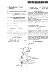
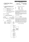
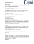
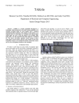
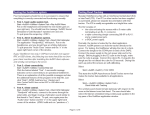
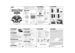
InertiaCube2 TM Bringing 3D To Life Manual for Serial Port Model InertiaCube2 Manual Doc. No. 072-IC210-0J01 1 User Manual for InertiaCube2 DLL Version 3.07 and higher Contacting InterSense Please do not hesitate to contact us for any reason. We are here to help and we value your business. InterSense Inc. 73 Second Avenue Burlington, Massachusetts 01803 USA Telephone: (781) 270-0090 Fax: (781) 229-8995 email: Internet: [email protected] www.isense.com Patents The label below identifies the protection granted by the Government of the United States to InterSense for its products: U.S. Patents 5645077, 5807284, 6162191 and Patents Pending INTERSENSE Trademarks InterSense™, InertiaCube™, InertiaCube 2TM SoniDisc™, GEOS™, PULSAR™, CONSTELLATION™ are trademarks of InterSense Inc. All other trademarks are the property of their respective owners. Copyright 2001 InterSense, Inc. InertiaCube2 Manual Doc. No. 072-IC210-0J01 Rev. 1.1 2 Precautionary Statements Any changes or modifications to the InertiaCube 2 not expressly approved by InterSense will void the warranty and any regulatory compliance issued for the system. Do not drop or otherwise shock the tracking devices for they can be permanently damaged. Do not bend, twist, pull strongly or tamper in any way with any part of the cabling. Take care to avoid electric shocks. Do not plug-in or unplug the power cable with wet hands. Please see Appendix C for Health and Safety warnings and guidelines InertiaCube2 Manual Doc. No. 072-IC210-0J01 Rev. 1.1 3 Table of Contents 1 THEORY OF OPERATIONS ................................................................................. 5 INERTIA CUBE2 ™ INTEGRATED INERTIAL INSTRUMENT ........................................... 5 3-DOF GYROSCOPIC EARTH- STABILIZED ORIENTATION SENSING (GEOS) ALGORITHMS.................................................................................................................... 6 1.1 1.2 2 SPECIFICATIONS AND PERFORMANCE CHARACTERISTICS ................ 8 2.1 2.2 2.3 3 PERFORMANCE SPECIFICATIONS ............................................................................. 8 CONNECTION SCHEME ............................................................................................ 8 COMPATIBILITY ...................................................................................................... 8 SETTING UP YOUR NEW INERTIACUBE2 ....................................................... 9 3.1 INERTIA CUBE2 COMPONENTS ................................................................................. 9 3.2 UNPACKING THE INERTIA CUBE2 SENSOR ................................................................ 9 3.3 SOFTWARE ............................................................................................................ 10 3.4 SETTING UP THE HARDWARE ................................................................................ 11 3.4.1 InertiaCube2 placement ............................................................................. 11 3.4.2 Computer/Power Connection .................................................................... 12 3.5 TRACKER USE GUIDELINES .................................................................................. 13 4 ISDEMO: TESTING THE INERTIACUBE2 ..................................................... 14 4.1 4.2 4.3 4.4 4.5 4.6 4.7 5 USING ISDEMO ................................................................................................... 14 ISDEMO: MAIN WINDOW .................................................................................... 16 FILE OPTIONS ........................................................................................................ 17 COMMUNICATIONS OPTIONS ................................................................................. 18 PARAMETER OPTIONS ............................................................................................ 19 DISPLAY OPTIONS ................................................................................................. 21 TOOLS OPTIONS .................................................................................................... 22 DEVELOPER’S INSTRUCTIONS....................................................................... 26 5.1 5.2 5.3 5.4 INTRODUCTION ..................................................................................................... 26 SAMPLE PROGRAM ............................................................................................... 26 USAGE .................................................................................................................. 27 API ....................................................................................................................... 28 6 APPENDIX A - FREQUEN TLY ASKED QUESTIONS.................................... 33 7 APPENDIX B – TROUBLESHOOTING............................................................. 34 8 APPENDIX C – HEALTH AND SAFETY WARNINGS AND GUIDELINES 35 9 APPENDIX D − CARE AND MAINTENANCE ................................................. 37 InertiaCube2 Manual Doc. No. 072-IC210-0J01 Rev. 1.1 4 1 Theory of Operations Congratulations for buying the finest orientation tracker on the market! This technology offers you several advantages: • • • Very low latency Unlimited range Smooth, jitter-free tracking The InertiaCube 2 is an inertial 3-DOF (Degree of Freedom) orientation tracking system. It obtains its motion sensing using a miniature solid-state inertial measurement unit, which senses angular rate of rotation, gravity and earth magnetic field along three perpendicular axes. The angular rates are integrated to obtain the orientation (yaw, pitch, and roll) of the sensor. Gravitometer and compass measurements are used to prevent the accumulation of gyroscopic drift. 1.1 InertiaCube2™ integrated inertial instrument The InertiaCube 2 is a monolithic part based on micro-electro-mechanical systems (MEMS) technology involving no spinning wheels that might generate noise, inertial forces and mechanical failures. The InertiaCube simultaneously measures 9 physical properties, namely angular rates, linear accelerations, and magnetic field components along all 3 axes. Microminiature vibrating elements are employed to measure all the angular rate components and linear accelerations, with integral electronics and solid-state magnetometers. The magnetometers are included for optional yaw drift correction in the sourceless inertial orientation mode only. The geometry and composition of these elements are proprietary, but the functional performance of the multisensor unit can be understood sufficiently by reference to the equivalent diagram in Figure 1. Figure 2 illustrates the basic physical principal underlying all Coriolis vibratory gyros. Suppose that the tines of the tuning fork are driven by an electrostatic, electromagnetic or piezoelectric drive to oscillate in the plane of the fork. When the whole fork is rotated about its axis, the tines will experience a Coriolis force F = ω X v pushing them to vibrate perpendicular to the plane of the fork. The amplitude of this out-of-plane vibration is proportional to the input angular rate, and it is sensed by capacitive or inductive or piezoelectric means to measure the angular rate. By way of comparison, a conventional inertial measurement unit (IMU) senses 6 of these properties using 6 separate instruments (3 rate gyros and 3 linear accelerometers) each of which by itself would typically be larger, heavier, and more expensive than an InertiaCube. Unlike conventional rate gyro and accelerometer instruments, which must be carefully aligned on a precision machined tri-axial mounting block, the InertiaCube is a monolithic device with its orthogonal outputs factory calibrated to precise alignment. Being a digital device using serial cables, the InertiaCube 2 cabling and connectorization is relatively non-critical, and the cables can be extended to over 100 feet without fear of contaminating sensitive analog signals. The power consumption of the InertiaCube 2 is 100 mA at 6VDC, which makes it suitable for prolonged operation from a small battery in future wireless applications. Figure 3 shows an InertiaCube 2 . InertiaCube2 Manual Doc. No. 072-IC210-0J01 Rev. 1.1 5 X ω x-mag. driven vibration v x-accel x-gyro F=ωXv Y z-gyro y-gyro y-accel sensed vibration y-mag. z-accel angular rate z-mag. Z Figure 1: Functional diagram of InertiaCube 2 Figure 2: Principle of Coriolis vibratory Gyroscope Figure 3: InertiaCube 2 1.2 3-DOF Gyroscopic Earth-stabilized Orientation Sensing (GEOS ) algorithms Figure 4 shows the processing which is used to compute orientation using this sensor configuration. The basic computation of orientation from gyroscopic angular rates (in the top line of boxes) provides the very rapid dynamic response and high resolution of the system. The accelerometers and magnetometers are used to stabilize the orientation to the earth’s gravitational and magnetic fields, thus eliminating the gradual but unbounded accumulation of gyroscopic drift errors. The Kalman filter uses an ever-evolving adaptive algorithm to discard the portion of the accelerometer measurements, which are due to actual motion instead of gravity. This is a very important step, because otherwise horizontal accelerations would result in very large transient pitch and roll errors known as “slosh”. The low cost sourceless trackers used in early consumer InertiaCube2 Manual Doc. No. 072-IC210-0J01 Rev. 1.1 6 HMDs are inclinometer/compass devices, and are thus intrinsically slosh-prone to the point of being uncomfortable to use. + InertiaCube ω x, ω y, ω z − Orientation ax, ay, az Perceptual Enhancement Algorithm Kalman Filter Orientation Error Estimator mx, my, mz Orientation Prediction Figure 4: GEOS mode tracking algorithm In the default operating GEOS mode, the reference frame (hereafter referred to as Navigation frame or Nav frame or N frame) is the locally-level geographic frame with its x-axis pointing north, y-axis east, and z-axis down. The Euler angles reported by the tracker can be described as a sequence of rotations applied to the InertiaCube starting with its body axes initially aligned with the Nav frame axes and resulting in the current orientation. The sequence starts with a rotation by (+yaw) about the Z axis, followed by a rotation by (+pitch) about the new Y axis (i.e. body frame axis), followed by a rotation by (+roll) about the new X axis (i.e. body frame x axis) X Roll Y Pitch Yaw Z The line from the magnetic field sensor outputs of the InertiaCube to the Kalman filter is a dotted line to indicate that the use of the magnetometers may optionally be disabled. The accelerometer measurements are sufficient to correct all the drift in pitch and roll, and the geomagnetic compassing function is only used to correct drift in yaw. In many fly-through applications absolute yaw referenced to magnetic north is not important and relative yaw tracking is sufficient. This is the case when the user can turn to face an obje ct or rotate the virtual world to bring that object into view. In these situations it may be desirable to turn magnetic yaw compensation off if there are large variations in the direction of magnetic north over the tracking area. With the compassing turned off, the yaw value will drift a few degrees per minute. This drift is too slow to notice while it is happening, but the cumulative yaw error may eventually become noticeable if the user is seated in a fixed chair, and then it may be necessary to apply a Heading Boresight. When yaw compensation mode is disabled, the Nav frame axes are aligned instead to pseudonorth, pseudo-east, and down, where pseudo-north is simply the direction the InertiaCube 2 x-axis was facing on power-up or after application of a Heading Boresight command. InertiaCube2 Manual Doc. No. 072-IC210-0J01 Rev. 1.1 7 2 Specifications and Performance Characteristics 2.1 Performance Specifications Degrees of Freedom: 3 (Yaw, Pitch, and Roll) Angular Range: Full 360º - All Axes Maximum Angular Rate: 1200º per second Minimum Angular Rate: 3º per second Static Accuracy: 1º RMS Dynamic Accuracy: 3º RMS Update Rate: 180 Hz Latency: 8 milliseconds Angular Resolution: 0.05º O/S Compatibility: Windows 98/2000/NT Interface: RS-232 Serial Size: 32mm x 29mm x 24mm Weight: 28 grams (0.98 ounce) Cable: 3.05 m (10 ft.) cable is provided. This cable is extendable to over 30.5 m (100 ft.) w/ InterSense provided extension cables. Power: 6 VDC via AC to DC Adapter (included - specify country) Power Consumption: 100 milliamps 2.2 Connection Scheme The InertiaCube 2 simply plugs into the RS-232 serial port of a computer. The AC to DC power adapter is plugged into your main power and the 6 VDC power plug connects to the serial port dongle. 2.3 Compatibility The InterSense InertiaCube 2 is PC compatible with Windows 95, 98, 2000 and XP. Third party software using the standard InterSense DLL is also supported. Please check with third party software providers or InterSense ([email protected]) about specific software compatibility and support. InertiaCube2 Manual Doc. No. 072-IC210-0J01 Rev. 1.1 8 3 Setting up your new InertiaCube2 3.1 InertiaCube2 Components InertiaCube 2 Serial Port Dongle & DC Power Jack 3.2 Unpacking the InertiaCube2 Sensor The InertiaCube orientation sensors come with 10-foot cables that plug into the RS-232 serial port of a computer. NOTE: The InertiaCube sensor is a precision instrument. Care must be taken when handling this device. Most of our customers attach the InertiaCube to devices that are more fragile than the InertiaCube and, hence, require that the whole system must be handled carefully. Although the product can withstand the normal wear and tear experienced by a premium HMD or other device, abrupt actions such as dropping it, or banging it against another object can permanently damage the InertiaCube. InertiaCube2 Manual Doc. No. 072-IC210-0J01 Rev. 1.1 9 AC to DC Power Adapter InertiaCube 2 Serial Port Dongle InertiaCube2 in packaging (Software CD not shown) 3.3 Software Test software and the DLL Software Development Kit (SDK) delivered with the InertiaCube 2 is provided on CD with the system. Use the auto install tool to extract and install the software. InertiaCube2 Manual Doc. No. 072-IC210-0J01 Rev. 1.1 10 3.4 Setting up the Hardware 3.4.1 InertiaCube 2 placement The InertiaCube is typically screwed or bolted to the object it is tracking (use of plastic or aluminum screws is recommended). As best as possible, locate the InertiaCube level to the ground in relation to its actual position during use: Correct Incorrect Optimally, you would mount the InertiaCube onto a base plate. In cases of anticipated vibration or physical shock, it is recommended that rubber-mounting pads be used. The mounting holes for the InertiaCube are illustrated below: InertiaCube2 Side View Mounting Holes (dimensions in inches) InertiaCube2 Manual Doc. No. 072-IC210-0J01 Rev. 1.1 11 InertiaCube2 Top View (dimensions in inches) The InertiaCube 2 comes with a 3.05 m (10’) cable attached. This cable plugs into the serial port dongle. The range of the InertiaCube is theoretically unlimited and is only restrained by the length of the cable that attaches it to the computer. A length of 3.05 meter (10 feet) is standard on all orders. Extension cables are available. Contact InterSense to order extension cables. 3.4.2 Computer/Power Connection The InertiaCube 2 is removed from packaging and plugged into the serial port power dongle as shown below. Connection of InertiaCube2 cable to serial port power dongle Next the AC to DC power converter is connected to wall power and the 6 VDC power jack is plugged into the serial port dongle jack. Finally, the serial port dongle is connected to your computer. Up to four (4) InertiaCubes can be connected to the PC using COM ports 1 thru 4. InertiaCube2 Manual Doc. No. 072-IC210-0J01 Rev. 1.1 12 3.5 Tracker Use Guidelines • Keep the InertiaCube(s) still for the first 10 seconds after starting your application software. • It is recommended, though not required, that you wait for the InertiaCube to warm up (it achieves optimal performance after warming up for at least 15-20 minutes). • The InertiaCube is tuned for normal head motion. Avoid shaking/vibration. Remember, this precision instrument uses angular rate sensors, which sense smooth, regular movement very well. If you keep these guidelines in mind, your InertiaCube 2 will deliver superb performance. InertiaCube2 Manual Doc. No. 072-IC210-0J01 Rev. 1.1 13 4 ISDEMO: Testing the InertiaCube2 ISDEMO is included as a test and diagnostics tool. With it you can test all the features of your tracker. Software included with your tracking device includes the following: 1) 2) 3) 4) isdemo32.exe d3dtrax.exe Software SDK Jmouse Program Win32 version. To be used under Windows95/98 and NT Direct 3D demo program See Section 5 for information Mouse emulator for full screen graphics applications ISDEMO provides a convenient graphical interface to validate the communication of the InertiaCube 2 to the PC and test performance through the standard InterSense DLL. See Section 5, Developers Instructions, to learn how to interface the InertiaCube 2 to software applications. 4.1 Using ISDEMO The first screen you’ll see is the hardware selection window (shown below). The program creates a different interface depending on the tracker model selected. Select the DLL Compatible option. Note: You must select DLL Compatible, or ISDEMO will not be able to correctly configure your tracker. InertiaCube2 Manual Doc. No. 072-IC210-0J01 Rev. 1.1 14 DLL Compatible DLL compatible trackers include all of InterSense’s tracking systems that use software applications programmed to the InterSense API which call functions through the InterSense DLL. Some InterSense trackers, like the InertiaCube 2 & InterTrax LC, are only DLL compatible. The InterSense precision line of trackers (IS-300, IS-600 and IS-900) can interface either directly through a serial port or via the DLL. IS-300 The IS-300 is a 3-Degree Of Freedom (DOF) tracker. It obtains its primary motion sensing data using a miniature solid-state inertial measurement unit (InertiaCube) which senses angular rate of rotation, gravity and earth components along three perpendicular axes. The angular rates are integrated to obtain the orientation (yaw, pitch, and roll) of the sensor. Gravitometer and compass measurements are used to prevent the accumulation of gyroscopic drift. IS-600 The IS-600 uses an InertiaCube to sense angular rate of rotation and linear acceleration along three perpendicular axes. The angular rates are integrated to obtain the orientation (yaw, pitch, and roll) of the sensor and the linear accelerations are transformed into a reference coordinate frame and double -integrated to keep track of changes in position (x, y, and z). Ultrasonic timeof-flight distance measurements are used to obtain a starting position and to correct any drift in the inertial position and orientation tracking. IS-900 The IS-900 is similar to the IS-600, except the roles of the SoniDiscs and ReceiverPods are reversed. Ultrasonic range measurements are made with respect to an array of SoniDiscs. The array is positioned over the required tracking area or on a wall behind the tracker or both. The SoniDiscs are triggered by infrared triggering codes, and they respond by emitting an ultrasonic chirp, which propagates through the air. Three ReceiverPods mounted in the tracker then detect this chirp. The ReceiverPods and associated electronics on the tracker measure the time-of-flight and thereby obtain range measurements from the camera to whatever SoniDiscs are nearby and visible. InertiaCube2 Manual Doc. No. 072-IC210-0J01 Rev. 1.1 15 4.2 ISDEMO: Main window ISDEMO has six primary menus in its main window: File Communications Parameters Display Tools Help InertiaCube2 Manual Doc. No. 072-IC210-0J01 Rev. 1.1 16 4.3 File options The File menu provides you with the following options: Select Hardware Device Reset Heading Exit Select Hardware Device System Initialization window (also seen at initial start-up) is shown when Select Hardware Device is selected. Use this window to select or detect the tracker model connected to your computer. Reset Heading Resets the current heading to zero. Exit Exits ISDEMO InertiaCube2 Manual Doc. No. 072-IC210-0J01 Rev. 1.1 17 4.4 Communications options This menu item will connect the tracker through the DLL. The DLL will automatically detect an InterSense tracker connect to COM ports 1 through 4 on the PC. The baud rate of the InertiaCube 2 is fixed at 115,200 baud. Make sure the computers serial port is capable of supporting this baud rate. The first two rates (kbps and records/s) displayed at the bottom of the window show the InertiaCube 2 update rates. The third rate (frames/s) shows the graphics update rate based on the PC’s hardware configuration. Detect Tracker InertiaCube2 Manual Doc. No. 072-IC210-0J01 Will reinitialize the DLL and detect the connected tracking device(s). Rev. 1.1 18 4.5 Parameter options Parameters menu gives you access to the tracker configuration controls. Station and Sensor Parameters The window shown below allows you to configure each InertiaCube 2 . The DLL version 3.07 can support up to four (4) stations, but ISDEMO only will allow interaction with one (1). Double clicking on the Station line or clicking the Change button will bring up the Station Configuration window where changes can be made. InertiaCube2 Manual Doc. No. 072-IC210-0J01 Rev. 1.1 19 Station Configuration window Station ON/OFF The station is always ON and data records will be sent continuously. Compass This controls the state of the compass component of the InertiaCube 2 . When station is configured for FULL compass mode, the readings produced by the magnetometers inside the InertiaCube are used as absolute reference orientation for yaw. Metallic objects and electronic equipment in close proximity to the InertiaCube can affect the magnetometers. When station is configured for PARTIAL compass mode, magnetometer readings are used to reduce drift and maintain stability, but not as an absolute measurement system. In this mode system is much less susceptible to magnetic interference, but heading drift will accumulate. If compass is OFF, no heading compensation is applied. Perceptual Enhancement Level (Not applicable for InertiaCube 2 – Consult InterSense if needed) Sensitivity Level (Not applicable for InertiaCube 2 – Consult InterSense if needed) Prediction Value (Not applicable for InertiaCube 2 – Consult InterSense if needed) InertiaCube2 Manual Doc. No. 072-IC210-0J01 Rev. 1.1 20 4.6 Display Options Start (and Stop) Displaying Data To display orientation data being received from the tracker, use the Start Displaying Data option in the Display menu or press Ctrl-D. InertiaCube2 Manual Doc. No. 072-IC210-0J01 Rev. 1.1 21 4.7 Tools Options System Information InertiaCube2 Manual Doc. No. 072-IC210-0J01 This window provides a summary of the InterSense tracker hardware and software configuration Rev. 1.1 22 UDP Broadcast Server This tool is used to broadcast tracker data over the network using UDP packets. Other machines on the network run client software that receives this data. Client software can only receive data, so stations and output records have to be configured here. Depending on available hardware, select one of the 4 available options for each of the stations: None Station is OFF and no data will be received from it. Generic 6DOF Only position and orientation data is available. Use this option with the InertiaCube 2 NOTE: A unique Network Port number, not used by any other computer on the network, should be assigned to the server. All client applications, including the ISDEMO, should InertiaCube2 Manual Doc. No. 072-IC210-0J01 Rev. 1.1 23 use that number to receive data. Default is 5001, and should not be changed unless there is a conflict. UDP Broadcast Client ISDEMO itself can be a UDP client. Simply enter the port on which data is transmitted and press Receive. As UDP packets are received, data can be displayed in the main window of ISDEMO. Isdriver Notes The latest version of ISDRIVER program has support for UDP client and is available from InterSense ([email protected]). It can be compiled for Win32 or UNIX, the network code has only been tested on IRIX and Linux so far. If you encounter any problems on other platforms, please contact InterSense and it will be corrected. File isense.h contains all definitions and function prototypes. There are extensive comments that explain the use of all functions. Win32 platform is detected automatically during compilation. On UNIX, however, you need to specify which flavor of UNIX you’re using. At the top of isense.h there are #defines that should be changed appropriately. File main.c contains a sample main and shows how to open a tracker, get and change station settings, read and display data, etc. The first parameter to ISD_OpenTracker is the port number. InertiaCube2 Manual Doc. No. 072-IC210-0J01 Rev. 1.1 24 Typically you should use 0, which will cause the program to first search for the tracker on the default network port 5001, then on all available RS232 ports. If you need to use a different network port, enter it as the first parameter to ISD_OpenTracker. A Makefile is not provided. To compile for UNIX, simply enter “cc *.c”. Help Facility InertiaCube2 Manual Doc. No. 072-IC210-0J01 Not currently supported in this ISDEMO release. All help information is contained in this manual. Rev. 1.1 25 5 Developer’s Instructions For DLL version 3.07 5.1 Introduction This document describes the interface to be used by the application software to initialize and retrieve data from the InterSense devices using the ISENSE.DLL. This dynamic link library is provided to simplify communications with all models of InterSense tracking devices, including IS-300, IS-600, IS-900, InertiaCube 2 and all versions of InterTrax. It can detect, configure, and get data from up to 4 trackers. The DLL maintains compatibility with existing devices, and also makes the applications forward compatible with all future InterSense products. 5.2 Sample Program The DLL is distributed with sample programs written in C and Visual Basic to demonstrate usage. It includes a header file with data structure definitions and function prototypes. Most of the API description below can also be obtained from the header file. main.cpp Main loop of the program. All API calls are made from here. isense.h Header file containing function prototypes and definitions, some of which are only applicable to InterSense Professional Series devices and are not used with InterTrax. This file should not be modified. isense.cpp DLL import procedures. This file is included instead of an import library to provide compatibility with all compilers, not just the VC++ 6.0. isense.dll The InterSense DLL. This file should be placed in the Windows system directory, or in the working directory of the application. InertiaCube2 Manual Doc. No. 072-IC210-0J01 Rev. 1.1 26 5.3 Usage The API provides an extensive set of functions that can read and set tracker configuration, but in its simplest form can be limited to just 4 calls, as shown below: void main() { ISD_TRACKER_HANDLE ISD_TRACKER_INFO_TYPE ISD_TRACKER_DATA_TYPE handle; tracker; data; handle = ISD_OpenTracker( NULL, 0, FALSE, FALSE ); if(handle > 0) printf( "\n Az El Rl X Y else printf( "Tracker not found. Press any key to exit" ); Z \n" ); while( !kbhit() ) { if(handle > 0) { ISD_GetData( handle, &data ); printf( "%7.2f %7.2f %7.2f %7.3f %7.3f %7.3f data.Station[0].Orientation[0], data.Station[0].Orientation[1], data.Station[0].Orientation[2], data.Station[0].Position[0], data.Station[0].Position[1], data.Station[0].Position[2] ); ", ISD_GetCommInfo( handle, &tracker ); printf( "%5.2fKbps %d Records/s \r", tracker.KBitsPerSec, tracker.RecordsPerSec ); } Sleep( 6 ); } ISD_CloseTracker( handle ); } InertiaCube2 Manual Doc. No. 072-IC210-0J01 Rev. 1.1 27 5.4 API ISD_TRACKER_HANDLE ISD_OpenTracker( HWND hParent, DWORD commPort, BOOL infoScreen, BOOL verbose ) hParent Handle to the parent window. This parameter is optional and should only be used if information screen or tracker configuration tools are to be used when available in the future releases. All included sample programs pass NULL. commPort If this parameter is a number other than 0, program will try to locate an InterSense tracker on the specified RS232 port. Otherwise it looks for USB device, then for serial port device on all ports at all baud rates. Most applications should pass 0 for maximum flexibility. If you have more than one InterSense device and would like to have a specific tracker, connected to a known port, initialized first, then enter the port number instead of 0. infoScreen This feature has not been implemented. Its purpose is to display an information window to show the tracker detection progress and results. Currently DLL writes only to Windows console. Most applications should pass False. verbose Pass True if you would like a more detailed report of the DLL activity. Messages are printed to Windows console. BOOL ISD_CloseTracker( ISD_TRACKER_HANDLE handle ) This function call de-initializes the tracker, closes communications port and frees the resources associated with this tracker. If 0 is passed, all currently open trackers are closed. When last tracker is closed, program frees the DLL. Returns FALSE if failed for any reason. handle InertiaCube2 Manual Doc. No. 072-IC210-0J01 Handle to the tracking device. This is the handle returned by ISD_OpenTracker. Rev. 1.1 28 BOOL ISD_GetTrackerConfig( ISD_TRACKER_HANDLE handle, ISD_TRACKER_INFO_TYPE *tracker, BOOL verbose ) Get general tracker information, such as type, model, port, etc. Also retrieves genlock synchronization configuration, if available. See ISD_TRACKER_INFO_TYPE structure definition for complete list of items. handle Handle to the tracking device. This is the handle returned by ISD_OpenTracker. tracker Pointer to a structure of type ISD_TRACKER_INFO_TYPE. See isense.h for structure definition. BOOL ISD_SetTrackerConfig( ISD_TRACKER_HANDLE handle, ISD_TRACKER_INFO_TYPE *tracker, BOOL verbose ) When used with IS Precision Series (IS-300, IS-600, IS-900) tracking devices this function call will set genlock synchronization parameters, all other fields in the ISD_TRACKER_INFO_TYPE structure are for information purposes only. handle Handle to the tracking device. This is the handle returned by ISD_OpenTracker. tracker Pointer to a structure of type ISD_TRACKER_INFO_TYPE. See isense.h for structure definition. BOOL ISD_GetCommInfo( ISD_TRACKER_HANDLE handle, ISD_TRACKER_INFO_TYPE *tracker) Get RecordsPerSec and KBitsPerSec without requesting genlock settings from the tracker. Use this instead of ISD_GetTrackerConfig to prevent your program from stalling while waiting for the tracker response. This call is used to obtain data rate information. handle Handle to the tracking device. This is the handle returned by ISD_OpenTracker. tracker Pointer to a structure of type ISD_TRACKER_INFO_TYPE. See isense.h for structure definition. InertiaCube2 Manual Doc. No. 072-IC210-0J01 Rev. 1.1 29 BOOL ISD_SetStationConfig( ISD_TRACKER_HANDLE handle, ISD_STATION_INFO_TYPE *station, WORD stationID, BOOL verbose ) Configure station as specified in the ISD_STATION_INFO_TYPE structure. Before this function is called, all elements of the structure must be assigned valid values. General procedure for changing any setting is to first retrieve current configuration, make the change, and then apply them. Calling ISD_GetStationConfig is important because you only want to change some of the settings, leaving the rest unchanged. This function is ignored if used with InterTrax30 and InterTrax2 products. InterTraxLC and InertiaCube2 only allow the Compass field to be changed. handle Handle to the tracking device. This is the handle returned by ISD_OpenTracker. station Pointer to a structure of type ISD_STATION_INFO_TYPE. See isense.h for structure definition. StationID Number from 1 to ISD_MAX_STATIONS. BOOL ISD_GetStationConfig( ISD_TRACKER_HANDLE handle, ISD_STATION_INFO_TYPE *station, WORD stationID, BOOL verbose ) Fills the ISD_STATION_INFO_TYPE structure with current settings. Function requests configuration records from the tracker and waits for the response. If communications are interrupted, it will stall for several seconds while attempting to recover the settings. handle Handle to the tracking device. This is the handle returned by ISD_OpenTracker. station Pointer to a structure of type ISD_STATION_INFO_TYPE. See isense.h for structure definition. StationID Number from 1 to ISD_MAX_STATIONS. InertiaCube2 Manual Doc. No. 072-IC210-0J01 Rev. 1.1 30 BOOL ISD_GetData( ISD_TRACKER_HANDLE handle, ISD_TRACKER_DATA_TYPE *data ) Get data from all configured stations. Data is places in the ISD_TRACKER_DATA_TYPE structure. Orientation array may contain Euler angles or Quaternions, depending on the settings of the AngleFormat field of the ISD_STATION_INFO_TYPE structure. TimeStamp is only available if requested by setting TimeStamped field to TRUE. Returns FALSE if failed for any reason. handle Handle to the tracking device. This is the handle returned by ISD_OpenTracker. data Pointer to a structure of type ISD_TRACKER_DATA_TYPE. See isense.h for structure definition. The structure is designed to accommodate InterSense Professional Series devices that support multiple sensors. In the case of the InterTrax series trackers, the only data available is Euler angles in the first element of the Station array. Orientation data order is Yaw, Pitch, Roll. BOOL ISD_GetCameraData( ISD_TRACKER_HANDLE handle, ISD_CAMERA_DATA_TYPE *Data ); Get camera encode and other data for all configured stations. Data is places in the ISD_CAMERA_DATA_TYPE structure. This function does not service serial port, so ISD_GetTrackerData must be called prior to this. Should only be used with IS Precision Series tracking devices, not valid and will be ignored if used with InterTrax. handle Handle to the tracking device. This is the handle returned by ISD_OpenTracker. data Pointer to a structure of ISD_CAMERA_DATA_TYPE. See isense.h for structure definition. InertiaCube2 Manual Doc. No. 072-IC210-0J01 Rev. 1.1 31 BOOL ISD_SendScript( ISD_TRACKER_HANDLE handle, char *command ); Send a configuration script to the tracker. Script must consist of valid commands as described in the interface protocol. Commands in the script should be terminated by the New Line character '\n'. Line Feed character '\r' is added by the function and is not required. Should only be used with IS Precision Series tracking devices, except InertiaCube2, not valid and will be ignored if used with InterTrax. BOOL handle Handle to the tracking device. This is the handle returned by ISD_OpenTracker. command Pointer to a string containing the command script. ISD_NumOpenTrackers( WORD *count ) Number of currently opened trackers is stored in the parameter passed to this function. BOOL ISD_ResetAngles( ISD_TRACKER_HANDLE handle, float yaw, float pitch, float roll ) Reset tracker angles to specified values, only serial version of InterTrax2 is supported in this release. BOOL ISD_ResetHeading( ISD_TRACKER_HANDLE handle, WORD stationNum ); Reset heading to zero. InertiaCube2 Manual Doc. No. 072-IC210-0J01 Rev. 1.1 32 6 Appendix A - Frequently Asked Questions Q1. What is the maximum length of the cable between the InertiaCube2 and the computer? The cable between the InertiaCube and the computer has been tested to a length of 100 feet. InterSense can provide longer cables. Please contact your sales representative for information. Q2. Does the InertiaCube have batteries? How often do they have to be changed? The InertiaCubes do not contain batteries. Q3. Are all the interconnection cables shielded? Yes. Q4. What is the MTBF of each component separately? Based on supplier data, the MTBF for the InertiaCube2 is estimated at 5 years. Q5. What type of shock can the InertiaCube2 sustain? These InertiaCube is designed to withstand a maximum acceleration of 500 g. Basically this means that a direct impact on the devices is not recommended. The InertiaCubes can withstand a higher level of shock if installed on the inside of an object, or mounted on rubber. Q6. What are the PIN assignments on the DB9 on the InertiaCube2 ? Pin 1 2 3 4 5 6 7 8 9 Function DCD RX TX DTR GND DSR RTS CTS RI Currently, the InertiaCube2 uses four wires; RX, TX RTS, and GND. Q7. Do you have any advice about working with software packages? Consult with the software vendor or contact InterSense [email protected]. Q8. How do I know whether I have the latest release of ISDEMO? Check our web site, the URL is http://www.isense.com/support.html . Click on the ISDEMO.ZIP hypertext link. We always post the latest release for you to download. InertiaCube2 Manual Doc. No. 072-IC210-0J01 Rev. 1.1 33 7 Appendix B – Troubleshooting Problem Reason/Solution ISDEMO doesn’t work! Most common reasons (not in any order): 1) Connected to wrong COM port plug on the back of the computer. 2) The selected serial port is captured by another program and can’t be opened by ISDEMO. 3) Serial port not capable of running at 115,200 baud rate. This is usually due to older computers that cannot run at 115,200 baud. The problem is a lack of a proper UART such as the 16550. 4) Incorrect port settings - use autodetect for Com parameters. 5) Not using Start Displaying Data. It may be necessary to select Stop Displaying Data first. ISDEMO is running, but system does not track Check for the following: 1) The InertiaCube 2 is not plugged in. 2) The InertiaCube 2 was plugged in after power up and a detect command has not been issued InertiaCube 2 interference Check for the following: 1) Placement directly on top of metal. You should place the InertiaCube an inch or two away. Orientation is drifting uncontrollably 1) Make sure that InertiaCube 2 is properly plugged in. 2) Keep InertiaCube 2 still for 10 seconds after connecting with ISDEMO or DLL. 3) Compass is turned off in ISDEMO. InertiaCube2 Manual Doc. No. 072-IC210-0J01 Rev. 1.1 34 8 Appendix C – Health and Safety warnings and guidelines Important: Most of the side effects described in this section usually only occur when a tracking device, like an InertiaCube2 , is used with personal displays or 3D glasses. The symptoms listed below are usually referred to as “Simulator Sickness”. Read and follow the user instructions. Before using InertiaCube 2 , read and follow the user instructions. In exceptional circumstances, failure to read and follow the user instructions could result in possible side effects that may lead to accidental injury during or after use. Recommended. For use only by persons 15 years of age or older. This system should not be used by: • Persons under the influence of drugs and alcohol. • Pregnant women. • Persons suffering from a heart condition • Persons with a history of epilepsy. Take frequent breaks. It is recommended that InertiaCube 2 should be used for no more than one hour at a time. After that you should take a 15-minute rest break before re-use regardless of how you feel. If you feel uncomfortable at any time, stop using immediately. Rest after using. Rest for at least 15 minutes after using InertiaCube 2 even if you feel fine and have experienced none of the symptoms described below. If you have experienced any undesirable effects or symptoms, rest until they are completely gone. Do not walk, drive, ride a bike or operate equipment until you have rested, otherwise you risk injury to yourself and others. Epilepsy and seizures. A very small part of the population has a condition that may result in epileptic seizures or loss of consciousness. If you or anyone in your family has epilepsy or has experienced seizures or loss of consciousness, do not use InertiaCube 2 without first consulting your physician. Persons who have not experienced seizures or loss of consciousness may still have an epileptic condition. We recommend that a non-user is always present when InertiaCube 2 is being used. InertiaCube2 Manual Doc. No. 072-IC210-0J01 Rev. 1.1 35 Additional possible risks of harm. While tracking technology has been used for many years, the range of sensors that are used to calculate positional and angular data continues to develop. Over the last twenty years as considerable amount of research has been conducted into possible side effects induced in users of real time computing systems that include various types of tracking sensors. This research has reported the symptoms described below from some users of these systems. InertiaCube 2 has been designed using the latest sensor technologies and we believe that the possibility of such symptoms occurring has been minimized. However, it is not possible to design for the individual characteristics of each user and it is possible that users will experience one or more of the side effects described below. Historic research shows that the effects or symptoms ordinarily occur during and immediately after use and should diminish quickly once the user stops using the system. We want you to make an informed and responsible choice about using the InertiaCube 2 . Accordingly, we warn you that even if you read and follow the User Instructions, you may experience one or more of the following effects or symptoms if you use InertiaCube 2 with a personal display: eye strain, altered vision, eye or muscle twitching, headaches, neck and shoulder strain, nausea and vomiting, disorientation, dizziness, impaired balance and stability, drowsiness, fainting, fatigue, sweating, extreme paleness, impaired hand-eye or other co-ordination. Each effect or symptom, if it occurs, should be temporary and may last from a few minutes to 30 minutes. InertiaCube2 Manual Doc. No. 072-IC210-0J01 Rev. 1.1 36 9 Appendix D − Care and Maintenance Care and Cleaning Recommended cleaning materials are the same as those for computers. Antistatic cloths can clean the components and reduce static electricity. Cleaning solutions should be applied to the cloth and not directly on any part of the system components. Phone & email support Any questions regarding the care and maintenance of your InertiaCube 2 can be handled by phone (781) 270-0090 or by email [email protected]. Please see the Support page at www.isense.com for the technical support contact information. Returns to InterSense Should you need to return any component of your system to InterSense for replacement or repair, contact InterSense prior to shipment to obtain a Return Material Authorization (RMA) Number and when shipping use the following address: InterSense Inc. 73 Second Avenue Burlington, MA 02129 USA Please note that InterSense will not be responsible for materials returned without an RMA number clearly marked on the outside of the shipping package. Batteries There are no batteries in the InertiaCube 2 system. Electrical power 6 VDC, 100 mA InertiaCube2 Manual Doc. No. 072-IC210-0J01 Rev. 1.1 37