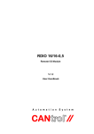
1
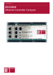
ZUNDEL Holding Enterprise
CE3CPU-P
Cell Controller
V.1.0
User Handbook
Copyright © BERGHOF Automationstechnik GmbH
Reproduction and duplication of this document and utilisation and communication of its content is
prohibited, unless with our express permission.
All rights reserved. Damages will be payable in case of infringement.
Disclaimer
The content of this publication was checked for compliance with the hardware and software described.
However, discrepancies may arise, therefore no liability is assumed regarding complete compliance.
The information in this document will be checked regularly and all necessary corrections will be included
in subsequent editions. Suggestions for improvements are always welcome.
Subject to technical changes.
Trademark
®
CANtrol // is a registered trademark of BERGHOFAutomationstechnik GmbH
General Information on this Manual
Content:
This manual describes the CANtrol module CE3CPU-P and its modifications. The product-related information contained herein was up to date at the time of publication of this manual.
Completeness:
This manual is complete only in conjunction with the user manual entitled
‘Introduction
to CANtrol Automation System’
and the product-related hardware or software user manuals required for the particular application.
Standards:
The CANtrol automation system, its components and its use are based on International Standard
IEC 61131 Parts 1 to 4 (EN 61131 Parts 1 to 3 and Supplementary Sheet 1).
Supplementary Sheet 1 of EN 61131 (IEC 61131-4) entitled ‘User Guidelines’ is of particular importance
for the user.
Order numbers:
Please see the relevant product overview in the ‘Introduction to CANtrol Automation System’ manual for
a list of available products and their order numbers.
Ident. No.:
2810520
You can reach us at:
BERGHOF Automationstechnik GmbH
Harretstr. 1
72800 Eningen / Germany
Phone: +49 7121 / 894-0
Telefax: +49 7121 / 894-100
e-mail: [email protected]
www.berghof-automation.de
BERGHOFAutomationstechnik GmbH works in accordance with DIN EN ISO 9001
BERGHOF Automation
CE3CPU-P
Update
Version
1.0
Date
19.04.07
Subject
First version
CE3CPU-P_HB_en_2D1052000ZD00.doc
3
CE3CPU-P
BERGHOF Automation
blank page
4
CE3CPU-P_HB_en_2D1052000ZD00.doc
BERGHOF Automation
CE3CPU-P
Contents
1.
GENERAL INSTRUCTIONS....................................................................................... 7
1.1.
Hazard Categories and Indications ......................................................................................................7
1.2.
Qualified users .......................................................................................................................................7
1.3.
Use as Prescribed ..................................................................................................................................8
2.
CE3CPU-P MODULE ................................................................................................. 9
2.1.
Overview .................................................................................................................................................9
2.2.
Technical Specifications .....................................................................................................................10
2.3.
Block Circuit Diagram..........................................................................................................................11
2.4.
Module View and Connection Assignment .......................................................................................12
2.5.
Subassembly Operation ......................................................................................................................13
2.5.1. Commissioning ........................................................................................................................13
2.5.2. Function Selection, Displays, Diagnostics...............................................................................13
2.5.3. Serial Interfaces .......................................................................................................................14
2.5.4. Ethernet Interface ....................................................................................................................15
2.5.5. USB Interface...........................................................................................................................16
2.5.6. CAN Interfaces (Standard Design) ..........................................................................................17
3.
ANNEX ..................................................................................................................... 19
3.1.
Environmental Protection ...................................................................................................................19
3.1.1. Emission ..................................................................................................................................19
3.1.2. Disposal ...................................................................................................................................19
3.2.
Maintenance/Upkeep............................................................................................................................19
3.3.
Repairs/Service ....................................................................................................................................19
3.3.1. Warranty ..................................................................................................................................19
3.4.
Nameplate .............................................................................................................................................20
3.5.
Addresses and Bibliography ..............................................................................................................22
3.5.1. Addresses ................................................................................................................................22
3.5.2. Standards/Bibliography............................................................................................................22
CE3CPU-P_HB_en_2D1052000ZD00.doc
5
CE3CPU-P
BERGHOF Automation
blank page
6
CE3CPU-P_HB_en_2D1052000ZD00.doc
BERGHOF Automation
General Instructions
1.
General Instructions
1.1.
Hazard Categories and Indications
The indications described below are used in connection with safety instructions you
will need to observe for your own personal safety and the avoidance of damage to
property.
These instructions are emphasised by bordering and/or shading and a bold-printed
indication, their meaning being as follows:
Immediate danger
Failure to observe the information indicated by this warning will result in death,
serious injury or extensive property damage.
Potential danger
Failure to observe the information indicated by this warning may result in death,
serious injury or extensive property damage.
Danger
Failure to observe the information indicated by this warning may result in injury or
property damage.
No hazard
Information indicated in this manner provides additional notes concerning the
product.
1.2.
Qualified users
Qualified users within the meaning of the safety instructions in this documentation
are trained specialists who are authorised to commission, earth and mark equipment, systems and circuits in accordance with safety engineering standards and
who as project planners and designers are familiar with the safety concepts of
automation engineering.
2VF100054FE01.doc
CE3CPU-P_HB_en_2D1052000ZD00.doc
7
General Instructions
1.3.
BERGHOF Automation
Use as Prescribed
This is a modular automation system based on the CANbus, intended for industrial
control applications within the medium to high performance range.
The automation system is designed for use within Overvoltage Category I
(IEC 364-4-443) for the controlling and regulating of machinery and industrial
processes in low-voltage installations in which the rated supply voltage does not
exceed 1,000 VAC (50/60 Hz) or 1,500 VDC.
Qualified project planning and design, proper transport, storage, installation, use
and careful maintenance are essential to the flawless and safe operation of the
automation system.
The automation system may only be used within the scope of the data and applications specified in the present documentation and associated user manuals.
The automation system is to be used only as follows:
•
as prescribed,
•
in technically flawless condition,
•
without arbitrary or unauthorised changes and
•
exclusively by qualified users
The regulations of the German professional and trade associations, the German
technical supervisory board (TÜV), the VDE (Association of German electricians)
or other corresponding national bodies are to be observed.
Safety-oriented (fail-safe) systems
Particular measures are required in connection with the use of SPC in safetyoriented systems. If an SPC is to be used in a safety-oriented system, the user
ought to seek the full advice of the SPC manufacturer in addition to observing any
standards or guidelines on safety installations which may be available.
As with any electronic control system, the failure of particular components
may result in uncontrolled and/or unpredictable operation.
All types of failure and the associated fuse systems are to be taken into account
at system level. The advice of the SPC manufacturer should be sought if necessary.
8
CE3CPU-P_HB_en_2D1052000ZD00.doc
2VF100054FE01.doc
BERGHOF Automation
CE3CPU-P Module
2.
CE3CPU-P Module
2.1.
Overview
Order number
The order/part no. is located on the nameplate of the individual modules for separate ordering.
Function
The Cell Controller is a real-time-capable control module with a broad spectrum of
data interfaces. The module can be programmed in “C” or in accordance with
IEC 61131-3 (CoDeSys 2.3).
Ethernet
An Ethernet interface operating at 10/100 MB/s is available. TCP/IP and UDP/IP
protocols permit extremely flexible linkage to visualization software, higher-level
control units or to the IT infrastructure.
USB
The USB host interface offers a widely used peripheral device interface. It can be
used, for example, in conjunction with a USB stick to carry out an application update or data download. Please contact our Technical Support staff is driver support
is not available for a specific USB device.
CAN interfaces
The Cell Controller is equipped with 1 standard CAN interface, which can be employed up to 1 MB/s.
Serial interfaces
The programming interface (RS232) can also be used by the application.
Overview of performance characteristics
Standard delivery
•
Motorola PowerPC 5200 CPU / 400 MHz
•
Application program and data memory (RAM):
64 MB on board; 32 MB for the application
•
Application program memory (Flash):
16 MB on board; 8 MB for the application
•
Retain memory: 16 KB
•
1 Ethernet 10/100 interface
•
1 USB Host interface
•
1 CAN interface
•
1 serial RS232 interface for programming tools and application
•
Maintenance free due to lack of backup battery
The standard control module delivery comprises:
•
2VF100128FE00.doc
CE3CPU-P control module
CE3CPU-P_HB_en_2D1052000ZD00.doc
9
CE3CPU-P Module
2.2.
BERGHOF Automation
Technical Specifications
Module data
Versions
Part no.
Development environment
Dimensions, WxHxD [mm]
Weight
Installation
Expansion
Operating temperature range
CPU
Programming software
CE3CPU-P-1131
203105000
CP1131 (as of V2.3) or CPC++
124 x 170 x 85.5 (in series dimensions W = 113/118.5)
approx. 700 g
Bearer rail, NS 35/7.5 EN 50022
No
5° C to 50° C (non-condensing) convection cooling assured
PPC 5200 / 400 MHz
IEC 61131-3 or high language “C” with real-time operating system
Application memory
Application program and data memory (RAM)
Application program memory
(Flash)
Retain memory
64 MB on board / 32 MB for the application
16 MB on board / 8 MB for the application
16 KB
EMI, protection class, insulation test, protection method
Interference emission
Interference resistance
Protection class
Insulation resistance
Protection method
EN 50081-2, industrial areas
EN 50082-2, industrial areas
III
EN 61131-2; DC 500 V test voltage
IP 20
Supply voltage, current consumption
Power supply, module electronics
(connection voltage)
Power supply, digital I/Os
Power consumption
Supply voltage polarity reversal
protection
Potential isolation
SELV DC +24 V < 0.4 A (EN 61131-2)
DC +24 V (EN 61131-2) divided into 3 groups
At Ue= DC +24 V in neutral, a max. of 500 mA,
Fuses, depending on the I/O loads: max. 10 A
Yes
Yes
Ethernet interface
Number / type of interfaces
Protocols
Connection technique
1 Ethernet 10/100 interface
TCP/IP and UDP/IP
RJ45 (ETH, X10)
USB interface
Number / type of interfaces
1 USB Host interface, V1.1 (X30)
Serial data interfaces
Number / type of interfaces
1 RS232 (X9) for programming / application
CAN interfaces
Number / type of interfaces
1 CAN ISO11898
CAN channel 0 (X7/X8) on the cover
Operating / display elements
LEDs
Operating mode selector switch
Programming
10
5 status LEDs; (not for the special timer inputs/outputs)
Yes, on the cover (S0)
Via Ethernet or RS232 port (X9)
CE3CPU-P_HB_en_2D1052000ZD00.doc
2VF100128FE00.doc
BERGHOF Automation
2.3.
CE3CPU-P Module
Block Circuit Diagram
X10
X9
X8
X7
SIO
SIO
Transceiver
CAN 0
CAN
Transceiver
UCST
S0 +
Status-LED
E-Bus
Interface
CAN0
SIO
CPU
RAM
DC
+5V
Mi
+8V
SMPN
DC
UCCPU
Serial
EEPROM
2VF100301DG00.cdr
2VF100128FE00.doc
CE3CPU-P_HB_en_2D1052000ZD00.doc
11
CE3CPU-P Module
2.4.
BERGHOF Automation
Module View and Connection Assignment
M1
L1+ / +24 V =
module electr.
1
2
I/O1
I/O2
I/O3
I/O4
IN5
IN7
IN6
IN8
IN9
IN10
IN11
IN12
I/O13
I/O14
I/O15
I/O16
M1
X1
1
2
3
4
5
6
7
8
9
10
11
12
13
14
15
16
17
18
X2
19
20
21
22
23
24
25
26
27
28
29
30
31
32
33
34
35
36
X3
37
L2+
38
I/O1
39
I/O2
40
I/O3
41
I/O4
42
IN5
43
IN6
44
IN7
45
IN8
46
IN9
47
IN10
48
IN11
49
50
51
53
52
IN12 I/O13 I/O14 I/O15 I/O16
Printable area for I/O labelling
54
L3+
Status LEDs
2
3
1
green
1
2
3
4
green
green
4
5
red
red
5
Power CAN
ON
active
S0
application specific
Nameplate
USB Host
X4
X5
X6
L4+ I/O17 I/O18 I/O19 I/O20
55
57
58
56
59
IN21
60
IN22
61
IN23
62
IN24
63
IN25
64
IN26
65
IN27
66
IN28
67
I/O29 I/O30 I/O31 I/O32
68
71
69
70
L5+
72
74
75
76
77
78
79
80
81
82
83
84
85
86
87
88
89
90
91
92
93
94
95
96
97
98
99
100
101
102
103
104
105
106
107
108
L6+
M6
IN27
IN28
I/O29
I/O30
I/O31
I/O32
73
I/O17
I/O18
I/O19
I/O20
IN21
IN22
IN23
IN24
IN25
IN26
Betriebswahlschalter /
operation mode selector switch
Printable area for I/O labelling
2VF100302DG00.cdr
12
CE3CPU-P_HB_en_2D1052000ZD00.doc
2VF100128FE00.doc
BERGHOF Automation
2.5.
CE3CPU-P Module
Subassembly Operation
Do not connect, apply, disconnect, or touch connectors during operation!
This could result in destruction or incorrect function. Prior to any work on the modules, switch all feeds off including those from connected peripheral devices, separately powered actuators, programming devices, etc.
2.5.1.
Commissioning
Before applying the supply voltage perform one last check of all connections to
make sure they are wired correctly and have the correct polarity.
Switch the supply voltage on.
For more information, please refer to the associated software documentation.
2.5.2.
Function Selection, Displays, Diagnostics
Operating mode
selector switch
Operating status
Used to switch between operating modes and to restart the module. This function
is software dependent.
Switch position
CP1131
CPC++
RUN (R)
CP1131 program in the RUN state; can be
changed with the programming device.
Freely programmable
STOP (S)
CP1131 program in the STOP state
Freely programmable
RESET (F)
CP1131 program (in RAM) and the
RETAIN variables will be deleted.
Freely programmable
Five operating status LEDs provide information concerning the current state of the
power supply, the module mode and other functions.
The status LEDs are also used to display error messages.
Operating status
LED state
Logical state
1
L1+ (green)
ON =
2
CAN status 2 (green)
ON =
Correct supply voltage to the module
electronics
CAN 0 send active
Operating status, CPC++
LEDs 3 to 5 can be controlled by the application software.
2VF100128FE00.doc
CE3CPU-P_HB_en_2D1052000ZD00.doc
13
CE3CPU-P Module
BERGHOF Automation
Operating status, CP1131
2.5.3.
Status3
(green)
Status4
(red)
Status5
(red)
Either
Either
On
At least one variable is force controlled
(FORCE).
On
Off
Either
Application program in the RUN state.
Off
On
Either
Application program in the STOP state.
Off
Flashing
Either
Application program in the ERROR STOP
state.
Flashing
On
Either
Application program in the breakpoint
STOP state.
Description
Serial Interfaces
The module is equipped with a serial interface (RS232) which can be used for programming or for the application.
X9:
RS232 programming interface
Pin
14
Signal
Description
1
Reserved
Do not connect
2
RXD
Received data
3
TXD
Transmitted data
4
Reserved
Do not connect
5
GND
Signal ground
6
Reserved
Do not connect
7
Reserved
Do not connect
8
Reserved
Do not connect
CE3CPU-P_HB_en_2D1052000ZD00.doc
2VF100128FE00.doc
BERGHOF Automation
2.5.4.
CE3CPU-P Module
Ethernet Interface
An Ethernet interface operating at 10/100 MB/s is available. TCP/IP and UDP/IP
protocols permit extremely flexible linkage to visualization software, higher-level
control units or to the IT infrastructure.
PC / HUB / CANtrol
Verbindungskabel 10BaseT mit Stecker RJ45
Interconnecting cable 10BaseT with plug RJ45
E TH E R N E T X 10
Kabel Kategorie 5 (KAT.5) / Cable Categorie 5 (CAT.5)
Aderquerschnitt / core cross-section min. 0,22 mm²
1 TD+ Stecker / plug
2 TD- contact view
Stecker / plug TD+ 1
contact view TD- 2
1
8
1
8
RD+ 3
RD- 6
3 RD+
6 RD-
CANtrol / Ethernet
Patch-Kabel 10BaseT mit Stecker RJ45
Interconnecting cable 10BaseT with plug RJ45
E TH E R N E T X 10
Kabel Kategorie 5 (KAT.5) / Cable Categorie 5 (CAT.5)
Aderquerschnitt / core cross-section min. 0,22 mm²
1 TD+ Stecker / plug
2 TD- contact view
Stecker / plug TD+ 1
contact view TD- 2
1
8
crossing pin 1 / 3
crossing pin 2 / 6
twisted pair
8
1
3 RD+
6 RD-
RD+ 3
RD- 6
2VF100238DG00.cdr
X10:
2VF100128FE00.doc
Ethernet pin assignment
Pin
Signal
Description
1
TD+
2
TD-
3
RD+
4
NC
Do not connect
5
NC
Do not connect
6
RD-
7
NC
Do not connect
8
NC
Do not connect
CE3CPU-P_HB_en_2D1052000ZD00.doc
15
CE3CPU-P Module
2.5.5.
BERGHOF Automation
USB Interface
Devices with USB connectors (x30) can be connected to the USB port (Rev. 1.1).
This is a USB host interface which delivers up to 500 mA of current at +5V.
The subassembly power pack also supplies the electronics on the E-bus expansion modules. If more than 100 mA are required at the USB interface, the maximum number of E-bus subscribers is reduced.
Pin assignment
X30
USB
B1
VCC
B2
D-
B3
D+
B4
GND
The only USB devices classes which can be employed for CoDeSys users are
USB sticks. A mouse can only be employed at the Linux level. The following points
must be taken into consideration when USB sticks are employed:
A USB stick may only be pulled during operation if all file operations have
been completed, otherwise the USB stick may become unusable!
If programs still have files open, the directory will no longer be able to be removed once the USB stick has been pulled. In this situation file or directory operations will result in blockages because information is to be read from a device
that is no longer available in the system. Therefore, always make sure that no
program still has open files in the USB stick before pulling the stick.
•
USB memory sticks can be inserted and pulled during operation. The inserted
device is automatically detected and mounted in the /media/usbX directory.
When the USB stick is pulled, the associated /media/usbX directory automatically “disappears” provided no program is currently accessing it (see above).
•
Either the first partition or, if there are no partitions, the entire memory will be
mounted on the memory stick, in other words, the associated directory appears
automatically.
•
The first stick is mounted under /media/usb0, the second under /media/usb1,
and so on. A maximum of 8 sticks may be inserted simultaneously
(/media/usb[0-7]). If a new (or previously inserted, then pulled) stick is inserted
it will be placed on the directory with the lowest number. Connecting a USB
hub allows multiple sticks to be operated at a given USB interface. Care must
be taken that no USB devices are still inserted in the hub when the hub is itself
inserted or pulled.
The mechanical structure of the USB port is designed for a maximum insertion
cycles.
16
CE3CPU-P_HB_en_2D1052000ZD00.doc
2VF100128FE00.doc
BERGHOF Automation
2.5.6.
CE3CPU-P Module
CAN Interfaces (Standard Design)
The CPU module is equipped with 1 CAN interface with CAN bus voltage levels in
accordance with ISO/DIS11898.
The standard CAN interfaces correspond to the description contained in the manual, “Introduction to CANtrol Automation Systems”.
CAN channel 0
X7/X8 on the front face
Aside from its duty as an application-specific communications interface, channel 0
also serves as the programming interface.
The max. baud rate is 1 MB/s and can be adjusted by software.
CAN Channel 0
CAN Channel 0
X7
CAN
CAN Channel 0
X8
CAN
CAN
Contr.
CPU
X9
SIO
2VF100303DG00.cdr
X7 / X8:
Pin assignment
Pin
Signal
Description
1
Reserved
Do not connect
2
CAN_L
CAN Low Signal
3
CAN_GND
Signal ground
4
Reserved
Do not connect
5
(CAN_SHLD)
Optional CAN shield
6
(GND)
Optional Signal ground
7
CAN_H
CAN High Signal
8
Reserved
Do not connect
9
(CAN_V+)
Optional external driver supply
For more information about connecting the CAN interface, please refer to the
manual, “Introduction to CANtrol Automation Systems”.
2VF100128FE00.doc
CE3CPU-P_HB_en_2D1052000ZD00.doc
17
CE3CPU-P Module
BERGHOF Automation
blank page
18
CE3CPU-P_HB_en_2D1052000ZD00.doc
2VF100128FE00.doc
BERGHOF Automation
Annex
3.
Annex
3.1.
Environmental Protection
3.1.1.
Emission
When used correctly, our modules do not produce any harmful emissions.
3.1.2.
Disposal
At the end of their service life, modules may be returned to the manufacturer
against payment of an all-inclusive charge to cover costs. The manufacturer
will then arrange for the modules to be recycled.
3.2.
Maintenance/Upkeep
Do not insert, apply, detach or touch connections while in operation – risk
of destruction or malfunction.
Disconnect all incoming power supplies before working on our modules; this also
applies to connected peripheral equipment such as externally powered sensors,
programming devices, etc. All ventilation openings must always be kept free of
any obstruction.
The modules are maintenance-free when used correctly.
Clean only with a dry, non-fluffing cloth.
Do not use detergents.
3.3.
Repairs/Service
Repair work may only be carried out by the manufacturer or its authorised service
engineers.
3.3.1.
Warranty
Sold under statutory warranty conditions. Warranty lapses in the event of unauthorised attempts to repair the equipment and/or product, or in the event of any other
form of intervention.
2VF100055FE01.doc
CE3CPU-P_HB_en_2D1052000ZD00.doc
19
Annex
3.4.
BERGHOF Automation
Nameplate
2VF100080DG01.cdr
20
CE3CPU-P_HB_en_2D1052000ZD00.doc
2VF100055FE01.doc
BERGHOF Automation
Annex
1
Barcode
same as identification number.
2
Module type
plain-text name of module.
3
Identification no.
module's identification number.
4
Model/order no.
You only need to give this number when ordering a module. The module will be
supplied in its current hardware and software version.
5
Version
defines the design-level of the module as supplied ex-works.
6
Supply voltage
7
Date
internal code.
8
CE mark
The ‘Version’ (supply version) panel specifies the design-level of the module as supplied ex-works.
When replacing a module, users, with the CNW (CANtrol Node Wizard) tool, can
read off the current software version of the newly supplied module, and then reload their 'own' software version for a particular project if necessary.
With the latter in mind, before the download you should always keep a record of
the existing software levels in your project documentation (software version, node
IDs, baud rate, etc.).
2VF100055FE01.doc
CE3CPU-P_HB_en_2D1052000ZD00.doc
21
Annex
BERGHOF Automation
3.5.
Addresses and Bibliography
3.5.1.
Addresses
CiA
'CAN in Automation', international manufacturers and users organisation
for CAN users in the field of automation:
CiA - CAN in Automation e.V.
Am Weichselgarten 26
D-91058 Erlangen /Germany
e-mail: [email protected]
http://www.can-cia.de
DIN-EN Standards
Beuth Verlag GmbH or
10772 Berlin
VDE-Verlag GmbH
10625 Berlin
IEC Standards
VDE Verlag GmbH
10625 Berlin
Internet search
http://www.iec.ch/
3.5.2.
or
Standards/Bibliography
IEC61131-1/EN61131-1
Programmable controllers Part 1: General information
IEC61131-2/EN61131-2
Programmable controllers Part 2: Equipment requirements and tests
IEC61131-3/EN61131-3
Programmable controllers Part 3: Programming languages
IEC61131-4/EN61131Bl1
Programmable logic controllers
Supplementary Sheet 1: User guidelines
EN 50081 Parts 1+2
German EMC Act: Emitted interference
EN 50082 Parts 1+2
German EMC Act: Noise immunity
ISO/DIS 11898
Draft International Standard: Road vehicles - Interchange of digital information Controller Area Network (CAN) for high-speed communication
EN 954-1
Safety of machinery: Safety-related parts of control systems (Part 1)
Bibliography
A variety of specialist publications on the CANbus is available from specialist
bookshops, or can be obtained through the CiA users' organisation.
Our Technical Support team will be glad to provide other literature references on
request.
22
CE3CPU-P_HB_en_2D1052000ZD00.doc
2VF100055FE01.doc