1
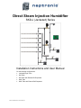
Direct Steam Injection Humidifier SKD-J (Jacketed) Series Installation Instructions and User Manual For the following configurations: Jacketed Single Tube Mini Rack Mini Rack with External Re-Evaporator Multi-Tube Multi-Tube with External Re-Evaporator SKD-J Humidifier Manual-140401-ESL.docx Direct Steam Injection Humidifier Installation Instructions and User Manual Foreword and Safety Instructions Neptronic Company Overview Founded in 1976, we’re a private corporation that designs, manufactures and distributes products for the HVAC industry. Our product line includes intelligent controllers, electronic actuators, actuated valves, humidifiers and electric heaters. Our products are designed and manufactured by over 250 dedicated employees in our 7,500 m2 (80,000 ft2) state-of-the-art facility located in Montreal, Canada. Using a vertical integration model, our entire manufacturing chain is under one roof from software and hardware development, to SMT circuit board assembly, to sheet metal fabrication, to product testing ensuring that our products are engineered to last. We currently hold several national and international patents and with our continued commitment to research and development, we provide innovative products and technologies for the ever-evolving challenges of the HVAC industry. Exporting over 70% of our sales, we have an exclusive distribution network around the globe that provides comprehensive solutions to our worldwide customers. About the Manual These installation and operation instructions have been developed to facilitate the installation of the Direct Steam Injection Humidifier. The strict application of these instructions will ensure the conformity of your installation and operation as per the manufacturer's recommendations. The application of these instructions is one of the conditions for the application of the warranty. The application of these instructions does not ensure, at any time conformity to procedures, regulation or local codes, regarding electric installation and connection to local water supply. This product has been declared to conform to the applicable Canadian and American safety standards and directives and bear the CSA (c) & (us) mark. The Certificate of Conformity, CSA is available, upon request with the manufacturer. 2012©: All rights reserved. This document cannot be reproduced totally or partially by any means whether, electronic, mechanical, photocopy, recording or other, without prior written authorization of Neptronic. Electricity All work concerned with electrical installation MUST only be performed by skilled and qualified technical personnel such as an electrician or a technician with appropriate training). The customer is always responsible for ensuring the suitability of the technical personnel. Please observe the local regulations concerning the provision of electrical installations. Correct Use Neptronic systems and its products are designed only for humidification use. Any other application is not considered appropriate for the intended purpose. The manufacturer cannot be made liable for any damage resulting from incorrect use. www.neptronic.com Page | i Direct Steam Injection Humidifier Installation Instructions and User Manual List of Figures Illustration 1 ‐ Jacketed Single Tube ............................................................................................................. 3 Illustration 2‐ Mini Rack ................................................................................................................................ 4 Illustration 3 ‐ Mini Rack with External Re‐Evaporator ................................................................................. 4 Illustration 4 ‐ Multi‐Tube ............................................................................................................................. 5 Illustration 5 ‐ Multi‐Tube with External Re‐Evaporator .............................................................................. 6 Illustration 6 ‐ Multi‐Tube for Large Capacities ............................................................................................ 7 Illustration 7 ‐ Installation Stages ................................................................................................................. 9 Illustration 8 ‐ Manifold Installation ........................................................................................................... 10 Illustration 9 ‐ End Mounting Bracket and Escutcheon Plate ..................................................................... 10 Illustration 10 ‐ Steam Header with Union ................................................................................................. 11 Illustration 11 ‐ Mini Rack ........................................................................................................................... 11 Illustration 12 ‐ Control Valve Orientation and Control Valve Angle .......................................................... 12 Illustration 13 ‐ Control Valve Connection to Steam Distributor without Header ..................................... 12 Illustration 14 ‐ Control Valve Connection with Header ............................................................................. 13 Illustration 15 ‐ Separator Proper Installation ............................................................................................ 13 Illustration 16 ‐ Separator Incorrect Installation ........................................................................................ 13 Illustration 17 ‐ Single Steam Distributor Separator Correct Installation ................................................... 14 Illustration 18 ‐ Single Steam Distributor Separator Incorrect Installation ................................................ 14 Illustration 19 ‐ Separator Connection to Control Valve ............................................................................ 14 Illustration 20 ‐ Re‐Evaporator Installation ................................................................................................. 15 Illustration 21 ‐ Re‐Evaporator Connections ............................................................................................... 15 Illustration 22 ‐ Temperature Sensor Separator Installation ...................................................................... 16 Illustration 23 ‐ Temperature Sensor Jacket Installation ............................................................................ 16 Illustration 24 ‐ Temperature Sensor Installation for Re‐Evaporator ......................................................... 17 Illustration 25 ‐ Separator Steam Trap Installation ..................................................................................... 17 Illustration 26 ‐ Steam Trap Installation: Distance from Temperature Sensor .......................................... 18 Illustration 27 ‐ Steam Trap Installation (Mini Rack and Multi‐Tube) ........................................................ 18 Illustration 28 ‐ Float and Thermostat Steam Trap Installation for Re‐Evaporator .................................... 19 Illustration 29 ‐ Control Valve Orientation and Control Valve Angle .......................................................... 19 Illustration 30 ‐ Jacketed Single Tube ......................................................................................................... 20 Illustration 31 ‐ Mini Rack and Multi‐Tube ................................................................................................. 21 www.neptronic.com Page | ii Direct Steam Injection Humidifier Installation Instructions and User Manual Contents Technical Specifications ................................................................................................................................ 1 Product Description .................................................................................................................................. 1 Configurations ............................................................................................................................................... 3 Jacketed Single Tube ................................................................................................................................. 3 Mini Rack ................................................................................................................................................... 4 Mini Rack with External Re‐Evaporator .................................................................................................... 4 Multi‐Tube ................................................................................................................................................ 5 Multi‐Tube with External Re‐Evaporator .................................................................................................. 6 Large Capacity Multi‐Tube ........................................................................................................................ 7 Handling and Packing .................................................................................................................................... 8 Installation Overview .................................................................................................................................... 9 Installation Method Statement ................................................................................................................. 9 Stage 1 – Steam Jacketed Distributor Installation .............................................................................. 10 Stage 2 – Steam Header Installation ................................................................................................... 11 Stage 3 – Control Valve Installation .................................................................................................... 12 Stage 4 – Steam Separator Installation ............................................................................................... 13 Stage 5 – Re‐Evaporator Installation .................................................................................................. 14 Stage 6 – Temperature Sensor Installation ......................................................................................... 16 Stage 7 – Float and Thermostatic Steam Trap Installation ................................................................. 17 Stage 8 – Isolating Valve Installation .................................................................................................. 19 Stage 9 – Y‐Strainer Installation .......................................................................................................... 20 Stage 10 – Electronic Steam Controller (SKDESC‐J) ............................................................................ 22 Initial Verification ........................................................................................................................................ 36 Installation .............................................................................................................................................. 36 Electrical .................................................................................................................................................. 36 Drain if needed (Mini Rack or Multi‐Tube) ............................................................................................. 36 Steam Supply .......................................................................................................................................... 36 Controls ................................................................................................................................................... 36 Start‐Up Procedure ..................................................................................................................................... 37 Start‐up ................................................................................................................................................... 37 Safety Test ............................................................................................................................................... 37 Reset the Set Point and Control Mode ................................................................................................... 37 End .......................................................................................................................................................... 37 General Conditions of Sales and Warranty ................................................................................................. 38 General warranty policy .............................................................................................................................. 38 Special agreement on components under warranty .................................................................................. 38 Notes ........................................................................................................................................................... 39 www.neptronic.com Page | iii Direct Steam Injection Humidifier Installation Instructions and User Manual Technical Specifications Product Description The Direct Steam Injection Humidifier injects and disperses atmospheric or low pressure steam into a building's air supply system to attain and maintain the desired humidity level. It uses steam from an inhouse boiler to humidify the air. The Direct Steam Injection Humidifier is controlled by an Electronic Steam Controller (SKDESC-J) that has been specifically designed to control and operate the humidifier. It comes with user-friendly features such as easy start-up and diagnostics, large LCD display, simple configuration options, and factory configured settings. It controls the sequence of operations to optimize energy efficiency and prevents condensate ejection. The following are the features of the Direct Steam Injection Humidifier and their functions: Jacketed Tube Steam Distribution. The steam dispersion tubes are made with stainless steel (1 3/8”). The jacketed tube steam distribution consists of a single tube or multiple horizontal tubes on a common vertical header. Upon a demand for humidity, the SKDESC-J controller opens the isolating valve to preheat the outer jacket. This prevents any condensate from forming in the inner tube that could wet the duct or AHU floor when steam is flowing through the tubes’ nozzles. When the jacket reaches its operating temperature, the ESC controller slowly opens the steam modulating valve feeding steam directly into the inner tube(s). The steam escapes the tube(s) through multiple calibrated nozzles and mixes with the airflow to maintain the desired humidity level. The following configurations are available with the jacketed tube steam distribution: o Single Tube o Multi-Tube o Mini Rack Each configuration suits a specific requirement and provides the following advantages: Low, medium, and high capacity applications o Average and short non-wetting distances o Duct, AHU, and limited space installations Separator. The separator is constructed with stainless steel. The separator supplies condensate-free steam to the steam control valve and discharges condensate to the steam trap. Control Valves. The Direct Steam Injection Humidifier comes with normally closed globe valve with equal percentage flow characteristics to control the flow of steam. It comes in variants such as bronze body and brass trim (stainless steel trim optional). The linear electric actuator is equipped with a heat shield. The control valves provide full modulation of the low pressure steam flow for a better control of the humidity level. Isolating Valves. The valves are the normally closed full port ball valve type made with bronze body and stainless steel trim. The valves control supply of the steam to the jacket in a multitube configuration or to the heat exchanger in a Direct Steam Injection Humidifier. Electronic Steam Controller (SKDESC-J). The SKDESC-J is a microprocessor based steam controller equipped with a backlit LCD display that allows programming the humidity setpoints and monitoring parameters such as actual humidity, airflow switch, interlock, temperature sensors efficient and easy. www.neptronic.com o Page | 1 Direct Steam Injection Humidifier Installation Instructions and User Manual Strainer. The strainer strains foreign matter from pipelines and protects the components of the steam humidifier. RTD Temperature Sensors. The Direct Steam Injection Humidifier comes with RTD temperature sensors integrated in a brass thermowell. The temperature sensors monitor steam temperature and detect abnormal condensate levels to ensure safe operations. Float and Thermostatic Steam Trap. The design comes with universal four port design, all stainless steel internal components with the option of a stainless steel body construction as well. The Float and thermostat eliminates condensate from the steam line. Steam Header with External Re-Evaporator. This option is available only with Multi-Tube with External Re-Evaporator and Mini Rack with External Re-Evaporator configurations. The header contains a re-evaporator that re-evaporates the condensate formed within the header and the steam dispersion tubes. The re-evaporator is made of copper with stainless steel connection. The re-evaporator is sized as per the system steam pressure to eliminate all the condensate produced. Therefore, no condensate is drained while in operation, resulting in reduction of energy wastage. www.neptronic.com Page | 2 Direct Steam Injection Humidifier Installation Instructions and User Manual Configurations The following configurations are available for Direct Steam Injection Humidifier. Jacketed Single Tube Illustration 1 - Jacketed Single Tube www.neptronic.com Page | 3 Direct Steam Injection Humidifier Installation Instructions and User Manual Mini Rack ISOLATING VALVE STRAINER ESCUTCHEON PLATES CONTROL VALVE SEPARATOR TEMPERATURE SENSOR FOR SEPARATOR VENTILATION DUCT STEAM JACKET DISTRIBUTOR AND HEADER (SINGLE PART) TEMPERATURE SENSOR FOR JACKET FLOAT AND THERMOSTATIC STEAM TRAP Illustration 2- Mini Rack Mini Rack with External Re-Evaporator ISO LATING VALVE STRAINER ESCUT CHEO N PLATES CO NT RO L VALVE SEPARATO R T EM PERATURE SENSO R FO R SEPARAT OR F LOAT AND THERM O STATIC STEAM TRAP VENTILATIO N DUCT STEAM JACKET DISTRIBUTOR AND HEADER (SING LE PART ) RE -EVAPO RATO R TEM PERATURE SENSOR FO R JACKET TEM PERATURE SENSO R FO R EXTERNAL RE -EVAPO RATO R FLO AT AND THERM O STATIC STEAM TRAP Illustration 3 - Mini Rack with External Re-Evaporator www.neptronic.com Page | 4 Direct Steam Injection Humidifier Installation Instructions and User Manual Multi-Tube ISOLATING VALVE (E) STEAM JACKET DISTRIBUTOR E STRAINER (H) A C I CONTROL VALVE (D) B HEADER (G) B SEPARATOR B 3/4'' NPT C B TEMPERATURE SENSOR FOR SEPARATOR (3/4" NPT) 3/4'' NPT VENTILATION DUCT FLOAT AND THERMOSTATIC STREAM TRAP (3/4" NPT) ESCUTCHEON PLATES TEMPERATURE SENSOR FOR JACKET (3/4" NPT) Illustration 4 - Multi-Tube www.neptronic.com Page | 5 Direct Steam Injection Humidifier Installation Instructions and User Manual Multi-Tube with External Re-Evaporator ISOLATING VALVE STRAINER HEADER VENTILATION DUCT CONTROL VALVE SEPARATOR STEAM JACKETED DISTRIBUTOR TEMPERATURE SENSOR FOR SEPARATOR FLOAT AND THERMOSTATIC STEAM TRAP ESCUTCHEON PLATES RE-EVAPORATOR TEMPERATURE SENSOR FOR RE-EVAPORATOR TEMPERATURE SENSOR FOR JACKET FLOAT AND THERMOSTATIC STEAM TRAP Illustration 5 - Multi-Tube with External Re-Evaporator www.neptronic.com Page | 6 Direct Steam Injection Humidifier Installation Instructions and User Manual Large Capacity Multi-Tube ISOLATING VALVE (E) ESCUTCHEON PLATES STRAINER (H) B C A B CONTROL VALVE (D) B B SEPARATOR TEMPERATURE SENSOR FOR JACKET 1 B B (3/4" NPT) B 3/4" NPT FLOAT AND THERMOSTATIC STEAM TRAP B ( TEMPERATURE SENSOR FOR SEPARATOR B HEADER (G) C 3/4" NPT) (3/4" NPT) 3/4'' NPT VENTILATION DUCT STEAM JACKETED DISTRIBUTOR FLOAT AND THERMOSTATIC STEAM TRAP ( 3/4" NPT) TEMPERATURE SENSOR FOR JACKET 2 (3/4" NPT) Illustration 6 - Multi-Tube for Large Capacities Note: This configuration is also available with re-evaporator option. www.neptronic.com Page | 7 Direct Steam Injection Humidifier Installation Instructions and User Manual Handling and Packing Handling and Lifting Lifting or handling MUST be carried out by trained and qualified personnel. Ensure that the lifting operation has been properly planned, assessed for risk and that the equipment has been checked by a competent Health & Safety representative, and effective control measures are in place. It is the customer’s responsibility to ensure that the operators are trained in handling heavy goods and to enforce the relevant lifting regulations. The Direct Steam Injection Humidifier MUST always be handled and lifted with care and should remain in its original packaging for as long as possible prior to installation. The Direct Steam Injection Humidifier package may be carried using a forklift from the underside. Caution should be exercised to ensure balanced load before lifting. Unpacking The Direct Steam Injection Humidifier is shipped inside carton boxes or in a wooden crate. Remove packing and skids prior to commissioning. www.neptronic.com Page | 8 Direct Steam Injection Humidifier Installation Instructions and User Manual Installation Overview All installation work must comply with local regulations. All work related to the installation of the Direct Steam Injection Humidifier MUST only be performed by skilled and qualified technical personnel such as plumbers or technicians with appropriate training. The customer is responsible for ensuring their suitability. For the installation of the Direct Steam Injection Humidifier and associated components, there are no specific tooling requirements. Installation Method Statement Stage 1 – Steam Jacketed Distributor Installation Stage 2 – Steam Header Installation (only with Mini Rack and Multi-Tube models) Stage 3 – Control Valve Installation Stage 4 – Steam Separator Installation Stage 5 – Installation of re-evaporator (only for models with re-evaporator option) Stage 6 – Temperature Sensor Installation Stage 7 – Float and Thermostatic Steam Trap Installation Stage 8 – Isolating Valve Installation Stage 9 – Y-Strainer Installation Stage 10 – Electronic Steam Controller (SKDESC-J) Illustration 7 - Installation Stages www.neptronic.com Page | 9 Direct Steam Injection Humidifier Installation Instructions and User Manual Stage 1 – Steam Jacketed Distributor Installation General Considerations Any installation work must be carried out by suitably qualified personnel. Consider the following points before deciding the location for the Direct Steam Injection Humidifier steam distribution system: Plan a location that is easy to access and permits an easy inspection and servicing of the humidifier. Do not install the humidifier where failure of the appliance could cause damage to the building structure or to other expensive equipment. Verify that the construction of the duct or AHU wall is suitable to support the steam distributors through the duration of the installation life. Positioning the Steam Distributors The steam distributors must be installed to ensure that the visible steam trail is kept to the shortest possible length. Steam nozzles should face the airflow to minimize the absorption and non-wetting distance. Locate the steam distributors far enough from elbow or fan to be in laminar air flow to ensure proper evaporation distance. There must be sufficient straight duct downstream from the steam distributors for absorption of the steam. Union Steam Jacketed Distributors Escutcheon plate End mounting plate Illustration 8 - Manifold Installation For Jacketed Single Tube applications, position the steam distributor in the middle of the duct. For Multi-Tube, position the steam distributors so that the distance between them is the same. Use proper size unions to connect the jacket of each steam distributor together. For Mini Rack models, position the system evenly so that the spacing between the top distributors and the duct/AHU is the same as the bottom distributors and the duct/AHU. Use metal screws to mount the escutcheon plate to the wall of the duct or AHU. Secure the end of the steam distributor with 3/8" (19.5 mm) rods either vertically or horizontally. Illustration 9 - End Mounting Bracket and Escutcheon Plate www.neptronic.com Page | 10 Direct Steam Injection Humidifier Installation Instructions and User Manual Stage 2 – Steam Header Installation Any installation work must be carried out by suitably qualified personnel. Steam Header Installation (Mini Rack and Multi-Tube only) Align the outlets of the steam header with the steam inlet of each steam distributor. For Multi-Tube, use proper size union to connect the steam header to the steam distributors. Refer to Illustration 10 - Steam Header with Union. The distance between the header and the steam distributor’s inlet port must not exceed 8” (203 mm) and both header and steam distributor ports must be aligned, no elbows can be used to pipe the connection. For Mini Rack models, the connections between the steam header and the steam jacketed distributors are assembled at the factory. The steam distributors and the header assembly come as separate, single parts. 8" (203 mm) Max Header Steam Dispersion Tube Union Illustration 10 - Steam Header with Union ISOLATING VALVE STRAINER ESCUTCHEON PLATES CONTROL VALVE SEPARATOR TEMPERATURE SENSOR FOR SEPARATOR VENTILATION DUCT STEAM JACKET DISTRIBUTOR AND HEADER (SINGLE PART) TEMPERATURE SENSOR FOR JACKET FLOAT AND THERMOSTATIC STEAM TRAP Illustration 11 - Mini Rack www.neptronic.com Page | 11 Direct Steam Injection Humidifier Installation Instructions and User Manual Stage 3 – Control Valve Installation Any installation work must be carried out by suitably qualified personnel. Control Valve Positioning The body of the valve must be positioned properly to have the steam supply going into the A port and exiting from the AB port. Do not refer to the orientation of the actuator head for positioning, since the head can be reversed. Install the actuated valve between 20 to 30 degrees from the vertical line to reduce the radiant heat to the actuator head. Illustration 12 - Control Valve Orientation and Control Valve Angle Control Valve Installation without Header (Jacketed Single Tube) Use the proper size union to connect the control valve to the steam distributor. The maximum distance between the steam control valve and the dispersion tubes port should be 8” (203 mm). UNION CONTROL VALVE WITH ACTUATOR STEAM DISTRIBUTOR Illustration 13 - Control Valve Connection to Steam Distributor without Header www.neptronic.com Page | 12 Direct Steam Injection Humidifier Installation Instructions and User Manual Control Valve Installation with Header (Mini Rack or Multi-Tube) Connect the steam control valve to the steam header by using a length of treaded pipe of the proper dimension. The connection between those must not exceed 8” (203 mm) and the steam control valve port must be aligned with the header inlet port. STEAM HEADER TO STEAM DISTRIBUTOR CONTROL VALVE WITH ACTUATOR Illustration 14 - Control Valve Connection with Header Stage 4 – Steam Separator Installation Any installation work must be carried out by suitably qualified personnel. Steam Separator Positioning The steam separator must be installed so that the steam inlet is always on top. The steam inlet and the condensate outlet must be vertical. S T E A M IN L E T M U ST ALW AYS BE O N TOP STEAM O UTLET CO NDENSATE O UTLET M U ST ALW AYS BE O N THE BOTTOM Illustration 15 - Separator Proper Installation S TE AM O U TLE T CONDENSATE O UTLET S T E A M IN L E T Illustration 16 - Separator Incorrect Installation Steam Separator Installation with Jacketed Single Tube Position the steam separator so that the steam inlet is always located on the top. The steam separator must be connected to the outlet of the jacketed distribution tube and must be positioned below the tube to avoid a build up of condensate in any area in the piping. www.neptronic.com Page | 13 Direct Steam Injection Humidifier Installation Instructions and User Manual D IS T R IB U T O R CO NTRO L VALVE W IT H A C T U A T O R SEPARATO R Illustration 17 - Single Steam Distributor Separator Correct Installation Illustration 18 - Single Steam Distributor Separator Incorrect Installation Steam Separator Installation (Mini Rack and Multi-Tube) Position the steam separator so that the steam inlet is always located on the top. The separator steam outlet port must be aligned with the steam control valve inlet port and the distance between the two must not exceed 8” (203 mm). Use the proper size of threaded pipe to connect the steam separator to the control valve. Reducing coupling might be needed to perform the installation between the separator and the steam control valve. Steam header Control valve with actuator Steam inlet Separator Steam outlet Condensate outlet 8" (203 mm) Maximum Illustration 19 - Separator Connection to Control Valve Stage 5 – Re-Evaporator Installation Any installation work must be carried out by suitably qualified personnel. Install a tee upstream the Isolating valve as indicated in the Illustration 20 - Re-Evaporator Installation. The Tee could also be on the vertical section of the piping between the jacket inlet and the isolating valve. www.neptronic.com Page | 14 Direct Steam Injection Humidifier Installation Instructions and User Manual ISOLATING VALVE CONTROL VALVE SEPARATOR RE-EVAPORATOR STEAM JACKET DISTRIBUTOR AND HEADER (SINGLE PART) Illustration 20 - Re-Evaporator Installation Connect that tee on the pressurized steam inlet port of the external re-evaporator as indicated in Illustration 21 - Re-Evaporator Connections. Illustration 21 - Re-Evaporator Connections Position the external re-evaporator lower than the header so that the atmospheric condensate generated within the header can flow down by gravity to the external reevaporator. Connect the header to the atmospheric condensate inlet of the external re-evaporator as indicated in Illustration 21 - Re-Evaporator Connections. Note that both side ports (atmospheric condensate inlet and capped port) can accept the atmospheric condensate. Cap the side port that is not connected to the header. Do not rotate external re-evaporator. The pressurized condensate connections must point vertically. www.neptronic.com Page | 15 Direct Steam Injection Humidifier Installation Instructions and User Manual Stage 6 – Temperature Sensor Installation Any installation work must be carried out by suitably qualified personnel. Temperature Sensor Installation General One temperature sensor shall be installed downstream of the condensate outlet of the steam separator. Refer to Illustration 22 - Temperature Sensor Separator Installation. SEPARATOR TEMPERATURE SENSOR SEPARATOR CAP Illustration 22 - Temperature Sensor Separator Installation Mini Rack and Multi-Tube applications will require at least one additional temperature sensor to be installed at the outlet of the steam jacket distributor. Depending on the total steam distributor length and number, the humidifier might require up to 4 temperature sensors on the steam jacket distributors. The system requires 1 temperature sensor for each 50 linear feet (15m) of steam distributors. Refer to Illustration 23 - Temperature Sensor Jacket Installation. Separator Condensate Outlet Temperature Sensor Separator Steam Jacket Distributor Outlet Cap Temperature Sensor Jacket Cap Illustration 23 - Temperature Sensor Jacket Installation www.neptronic.com Page | 16 Direct Steam Injection Humidifier Installation Instructions and User Manual Temperature Sensor Installation for Re-Evaporator If using the external re-evaporator option, an additional temperature sensor must be installed downstream the pressurized steam outlet of the re-evaporator as indicated in Illustration 24 - Temperature Sensor Installation for Re-Evaporator. Illustration 24 - Temperature Sensor Installation for Re-Evaporator Stage 7 – Float and Thermostatic Steam Trap Installation Any installation work must be carried out by suitably qualified personnel. Float and Thermostat Steam Trap Installation Install a float and thermostatic steam trap at each condensate outlet of the Direct Steam Injection Humidifier system. Do not combine return steam lines into one steam trap. Steam traps can only be combined on the condensate side. The outlet of the float and thermostat steam trap should be connected to the condensate return pipe of the steam boiler system. The distance between the temperature sensor and the steam trap must be between 5” and 7” (100-175 mm). SEPARATOR TEMPERATURE SENSOR SEPARATOR CAP FLOAT AND THERMOSTATIC STEAM TRAP Illustration 25 - Separator Steam Trap Installation www.neptronic.com Page | 17 Direct Steam Injection Humidifier Installation Instructions and User Manual 6" (152 mm) Illustration 26 - Steam Trap Installation: Distance from Temperature Sensor Separator Condensate Outlet Steam Jacket Distributor Outlet Steam Header Condensate Outlet Float and Thermostatic Steamtrap Header Steamtrap Illustration 27 - Steam Trap Installation (Mini Rack and Multi-Tube) For Mini Rack and Multi-Tube applications, connect the header steam trap, refer to Illustration 27 - Steam Trap Installation (Mini Rack and Multi-Tube), to the drain since there is no pressure upstream of the steam control valve to push the condensate back to the boiler. Therefore, normal draining design applies on the condensate side of the header steam trap slope to evacuate the condensate, and a P-trap (6” or 152 mm) to avoid the steam vapor coming from the drain. All other steam traps can be connected to the condensate return line. If draining condensate is not desired, select the external re-evaporator option to be able to return all condensate to the condensate return line. Float and Thermostat Steam Trap Installation for Re-Evaporator If using the re-evaporator option, the steam trap connected to the re-evaporator can be connected to the condensate return line as shown in the Illustration 28 - Float and Thermostat Steam Trap Installation for Re-Evaporator. www.neptronic.com Page | 18 Direct Steam Injection Humidifier Installation Instructions and User Manual Illustration 28 - Float and Thermostat Steam Trap Installation for Re-Evaporator Stage 8 – Isolating Valve Installation Any installation work must be carried out by suitably qualified personnel. Isolating Valve Positioning The valve body must be positioned properly to have the steam supply going into the A port and exiting from the AB port. Do not refer to the orientation of the actuator head for positioning, since the head can be reversed. Install the actuated valve between 20 to 30 degrees from the vertical line to reduce the heat transfer to the actuator head. Illustration 29 - Control Valve Orientation and Control Valve Angle www.neptronic.com Page | 19 Direct Steam Injection Humidifier Installation Instructions and User Manual Stage 9 – Y-Strainer Installation Any installation work must be carried out by suitably qualified personnel. Strainer Positioning The strainer must be installed upstream the separator and the isolating valve for any Direct Steam Injection Humidifier configuration. On the Jacketed Single Tube applications, install the strainer before installing the isolating valve. Refer to Illustration 30 - Jacketed Single Tube. For Mini Rack and Multi-Tube applications, install the strainer before the steam line splits between the separator and the isolating valve. Refer to Illustration 30 - Jacketed Single Tube. Isolating Valve Ventilation Duct Strainer Control Valve Steam Jacketed Distributor Separator Escutcheon Plate Temperature Sensor for Separator Float and Thermostatic Steam trap Illustration 30 - Jacketed Single Tube www.neptronic.com Page | 20 Direct Steam Injection Humidifier Installation Instructions and User Manual STRAINER (H) ISOLATING VALVE (E) C ESCUTCHEON PLATE A E CONTROL VALVE (D) B F D B SEPARATOR 3/4" NPT F C HEADER TEMPERATURE SENSOR FOR SEPARATOR (3/4" NPT) E 3/4'' NPT VENTILATION DUCT STEAM JACKET DISTRIBUTOR WITH HEADER ( SINGLE PART ) FLOAT AND THERMOSTATIC STEAM TRAP (3/4" NPT) TEMPERATURE SENSOR FOR JACKET 1 (3/4" NPT) FLOAT AND THERMOSTATIC STEAM TRAP (3/4" NPT) Illustration 31 - Mini Rack and Multi-Tube Note: The above illustration is shown without the re-evaporator option. www.neptronic.com Page | 21 Direct Steam Injection Humidifier Installation Instructions and User Manual Stage 10 – Electronic Steam Controller (SKDESC-J) Models SKDESC-J SKDESC-JB with BACnet Communication SKDESC-JD with Modbus Communication Description The Electronic Steam Controller SKDESC-J is made specifically for Neptronic SKD-J (Jacketed) Humidifiers. Features Conserves energy and eliminates condensate (dry operation) o Manages isolating and modulating valves o Pre-heats tube jackets on demand for humidity ESC Steam Controller Series Automatic temperature sensor adjustment On/Off or Modulating control Selectable internal or external control Configurable proportional control band & dead band Selectable Fahrenheit or Celsius scale BACnet or Modbus models available 24 Vac power supply (by others) Easy start up and troubleshooting Backlit LCD with simple icon and text driven menus Technical Specifications Description Power Supply Power Consumption Relay Output Relay Rating Communication Operating Temperature Storage Temperature Relative Humidity Weight Dimensions A = 6.3” | 160mm B = 5” | 126mm C = 2.25” | 57mm SKDESC-J SKDESC-JB 24 Vac 50 VA 2 relay 125 Vac, resistive load 10 amps BACnet 0ºC to 50ºC [32ºF to 122ºF] -30ºC to 50ºC [-22ºF to 122ºF] 5 to 95% non condensing 635 g. [1.4 lb] A SKDESC-JD Modbus C B www.neptronic.com Page | 22 Direct Steam Injection Humidifier Installation Instructions and User Manual Wiring We strongly recommend that all Neptronic products be wired to a separate grounded transformer and that transformer shall service only Neptronic products. This precaution will prevent interference with, and/or possible damage to incompatible equipment. On/Off 5 4 2 1 6 5 4 3 2 1 NC 3- Control Signal 24 Vac 4- 24 Vac TS5 2 COM 3 TS6 1 NC 3 2 Steam Relay TB3 NO KCOM 2 TS4 1 RE 24VAC 2- Not used Isolating Valve Signal NO 1 COM 3 Common Temperature Sensor REEVAP TO1 1- Common Common Steam on Relay Status Alarm Relay 4 2 J4 COM 24VAC 3 TS3 Temperature Sensor Jacket 4 AT060 TO2 24 Vac COM 2 1 Common J3 Isolating Valve Actuator 1 3 TS2 Temperature Sensor Inputs TB12 TB13 COM Temperature Sensor Jacket 2 Temperature Sensor Jacket 3 TB11 TS1 2 J2 TO3 Alarm Relay TB4 AI4 1 J1 NO PD Switch On/Off Common or 24 Vac COM KCOM Supply 3 Common NC DI1 TB5 COM Temperature Sensor Separator Temperature Sensor Jacket 1 Analog Inputs TB10 2 S1 AI3 NC TB9 High Limit Humidity Sensor2 TB2 3 AI2 Room Humidity Sensor Analog Outputs COM 1 AI1 2 0 – 10 Volts AO2 1 External Demand/Setpoint1 COM 4 Not used -5 AO1 3 Common Not used -4 24VAC 2 Control Signal -3 1 24 Vac Control Valve Signal DI2 3 5 OUT B- High Limit (digital)2 TB1 4 OUT A+ TB8 COM Common -1 24 Vac -2 Network* 3 AM060-ESC 2 Steam Control Valve Actuator IN A+ IN B- DI3 COM DI4 Digital Input TB7 1 * Network available only on SKDESC-JB or SKDESC-JD Interlock 3 SKDESC-J 5 Interlock: Contact opening = alarm and unit shutdown 4 Hi Limit: Contact opening = alarm and unit shutdown 3 COM 2 PD Switch: Contact opening = alarm and unit shutdown 1 Demand: Contact closure = Override and force 100% demand Temperature Sensor Jackets 1-2-3-4-reevap sensor are optional, depending on system configuration. Step Step 12, “Control Mode” = extern Description Used for external control signal Step 12 “Control Mode” = intern and Used for external setpoint signal Terminal Block TB9 Pin 1 Step 17, “Externa Humidty Setpnt” = on Step 23, “High limit sensor” = digital Used for connecting high limit sensor (Digital) TB1 Pin 4 Step 23, “High limit sensor” = analog Used for connecting high limit sensor (Analog) TB10 Pin 1 www.neptronic.com Page | 23 Direct Steam Injection Humidifier Installation Instructions and User Manual Symbols used in this manual Humidity Temperature Communication/Network Air Flow Timer/Clock Programming Mode Press to enter edit mode * Setting Description Setting Value Scroll or change value when in edit mode Press to exit To enter the Programming Mode, perform the following steps: 1. Press to start and enter password (see Step 1 “enter passwrd” ). 2. Use the arrows buttons 3. Press 4. Once in edit mode, use the arrows buttons automatically saved. 5. Press 6. Return to step 2 or press minutes. or to navigate the menu. to enter edit mode of the displayed value. or to change values. Changed values are to exit edit mode of the displayed value. to exit the mode. Auto exits if no actions are taken after 5 “enter passwrd” 1. Value: 637 Enter the password within 1 minute. After entering the correct password, press to proceed. If you enter the wrong password, the controller returns to the normal operation mode and you have to repeat this step. “languag” 2. Default: Range: ENG (English) ENG (English) Select the desired language. 3. “metric display units” Default: ON Range: ON (metric units - ºC, kg H2O/Hr), OFF (imperial units - ºF, lbs H2O/Hr) Select the desired measurement system. www.neptronic.com Page | 24 Direct Steam Injection Humidifier Installation Instructions and User Manual “econo mode” 4. Default: Range: OFF (econo mode deactivated) ON (econo mode activated), OFF (econo mode deactivated) In Econo mode, the isolation valve will be closed when there is no demand. Important: For correct operation, set the econo mode feature to OFF (econo mode deactivated). 5. “working capacit in pct” Default: 100% Range: 10 to 100% Increment: 5% This option enables you to adjust the maximum demand capacity of the full system capacity in %. This percentage is a factory setting. We recommend that you do not change this value without consulting Neptronic. 6. “separat temper offset” Default: 0 Range: -10 to 10ºC Increment: 0.1ºC [-18 to 18ºF] [0.1ºF] Set the desired temperature reading. “Jacket1 temper offset” 7. Default: Range: Increment 0 -10 to 10ºC 0.1ºC [-18 to 18ºF] [0.1ºF] This option appears only if the number of temperature switches is greater than 1. Adjust the temperature reading by using the offset. “Jacket2 temper offset” 8. Default: Range: Increment: 0 -10 to 10ºC 0.1ºC [-18 to 18ºF] [0.1ºF] This option appears only if the number of temperature switches is greater than 2. Adjust the temperature reading by using the offset. 9. “Jacket3 temper offset” Default: 0 Range: -10 to 10ºC Increment: 0.1ºC [-18 to 18ºF] [0.1ºF] This option appears only if the number of temperature switches is greater than 3. Adjust the temperature reading by using the offset. 10. “Jacket4 temper offset” Default: 0 Range: -10 to 10ºC Increment: 0.1ºC [-18 to 18ºF] [0.1ºF] This option appears only if the number of temperature switches is greater than 4. Adjust the temperature reading by using the offset. www.neptronic.com Page | 25 Direct Steam Injection Humidifier Installation Instructions and User Manual 11. “reevap temper offset” Default: 0 Range: -10 to 10ºC Increment: 0.1ºC [-18 to 18ºF] [0.1ºF] This option is only available on humidifiers with the "re-evaporator" feature. Adjust the temperature reading by using the offset. 12. “Control Mode” Default: Range: Extern Intern, Extern, Net Select the desired control mode from the available options. If Intern is selected: the humidifier is controlled by the SKDESC-J. If Extern is selected: the humidifier is controlled by an external signal. If Net is selected: the humidifier is controlled over the network. This option is available only on SKDESC-JB and SKDESC-JD models. If you selected Intern or Net, go to Step 14“network room humidty”. 13. “demand signal range” Default: 2-10 Vdc Range: 0-10 Vdc, 2-10 Vdc Select the desired relative humidity sensor signal. 14. “network room humidty” Default: OFF Range: OFF, ON This option is only available on BACnet or Modbus models (SKDESC-JB or SKDESC-JD). Select ON if you want to control the humidity over the network. If you selected ON, go to Step 17 “Externa Humidty Setpnt”. If you selected Intern at Step 12 “Control Mode”, go to Step 16 “Room humidty signal range”. 15. “room humidty offset in pct” Default: 0% RH -10 to 10% RH Range: Increment: 0.1% RH Adjust the room relative humidity reading by using the offset. 16. “Room humidty signal range” Default: Range: 2-10 Vdc 0-10 Vdc, 2-10 Vdc Select the desired signal range from the available options. If you selected Extern at Step 12 “Control Mode”, go to Step 23 “High limit sensor”. 17. “Externa Humidty Setpnt” Default: Range: OFF OFF, ON Select ON if you want to use an external setpoint for humidity. If you selected OFF, go to Step 19 “interna humidty setpnt in pct”. www.neptronic.com Page | 26 Direct Steam Injection Humidifier Installation Instructions and User Manual 18. “setpnt signal range” Default: 2-10 Vdc Range: 0-10 Vdc, 2-10 Vdc Select the desired relative humidity sensor signal. Go to Step 20 “control dead band in pct”. 19. “interna humidty setpnt in pct” Default: 40% RH Range: 10% to 90% RH Increment: 1% RH Set the desired humidity setpoint in % RH. 20. “control dead band in pct” Default: 2.0% RH Range: 0% to 5% RH Increment: 0.1% RH Set the desired control dead band. 21. “control Prop ramp in pct” Default: 5.0% Range: 1% to 10% Increment: 0.1% Set the desired control proportional ramp. 22. “control integra ramp in pct” Default: 5.0% Range: 1% to 10% Increment: 0.1% Set the desired control integral ramp. 23. “High limit sensor” Default: Digital (On/Off) Range: Disable, Analog, Digital (On/Off), Network Select the desired type of high limit sensor from the available options. The Network option is available only on BACnet or Modbus models (SKDESC-JB or SKDESC-JD). If you selected Digital, go to Step 28 "High limit max demand in pct”. If you selected Disable, go to Step 29 "end of season delay in hr”. 24. “High limit setpnt in pct” Default: 80% RH Range: 10% to 90% RH Increment: 1% RH Set the high limit relative humidity setpoint. 25. “High limit prop ramp in pct” Default: 10.0 % Range: 0% to 20% Increment: 0.1% Set the desired high limit proportional ramp. If you selected Network at Step 23 “High limit sensor”, go to Step 28 "High limit max demand in pct”. www.neptronic.com Page | 27 Direct Steam Injection Humidifier Installation Instructions and User Manual 26. "High limit humidty offset in pct” Default: 0% RH Range: -10% RH to 10% RH Increment: 0.1% RH Adjust the relative humidity reading of the room. 27. "High limit signal range” Default: 2-10 Vdc Range: 0-10 Vdc, 2-10 Vdc Select the high limit signal range. 28. "High limit max demand in pct” Default: No default (information display only) Displays the actual reading of the high limit sensor. 29. "end of season delay in hr” Default: 100 hours Range: 100 to 250 hours Increment: 5 hours This option does not appear if you have selected econo mode at Step 4 “econo mode”. Indicates that the isolation valve will be turned off after 100 hours if there is no demand. 30. "service delay in hr” Default: 1000 hours Range: 400 to 1500 hours Increment: 100 hours Set the number of hours running at 100% capacity before servicing is due. 31. "service runtime in hr” Default: No default (information display only) Displays the running time in hours at 100% capacity since the last service has been performed. To reset this value to 0 and reset any associated alarms, press the edit button and then press and hold both and arrow keys. 32. “runs while service alarm” Default: ACt (active) Range: INACt (Inactive), ACt (active) Select ACt to enable the system to run even when the servicing is due. 33. “total runtime in hr” Default: No default (information display only) Displays the running time in hours at 100% capacity. www.neptronic.com Page | 28 Direct Steam Injection Humidifier Installation Instructions and User Manual 34. "auto baud rate” Default: Range: ON ON, OFF This option is available only on BACnet or Modbus models (SKDESC-JB or SKDESC-JD). Enable or disable Auto Baud Rate detection. When enabled, the controller automatically configures its baud rate by detecting the network speed upon connection to the network. When disabled, you must manually select the baud rate. (go to Step 35, “baud rate”) 35. “baud rate” Default: Range: BACnet Modbus No default (information display only) 9.6k, 19.2k, 38.4k, 76.8k 9.6k, 19.2k, 38.4k, 57.6k This option is available only on BACnet or Modbus models (SKDESC-JB or SKDESC-JD). If you selected ON at the previous step, the controller automatically detects and displays the baud rate. If you selected OFF at the previous step, select the baud rate value from the available options. 36. “network address” BACnet Default: Range: 0 0 to 254 Modbus Default: Range: 1 1 to 246 This option is available only on BACnet or Modbus models (SKDESC-JB or SKDESC-JD). Select the desired address. 37. “adjust device instance” Default: Range: 0153001 No, Yes To change the device instance, select Yes. If you select No, the device instance will be modified automatically according to the MAC address. 38. “network parity” Default: None Range: None, Odd, Even This option is available only on Modbus model (SKDESC-JD). Select the desired parity control from the available options. 39. “network stop bits” Default: 1 Range: 1,2 This option is available only on Modbus model (SKDESC-JD). Select the desired network stop bits. 40. “Network fallback timeout” Default: 0 sec Range: 0 to 900 sec Increment: 1 sec This option appears if you've set one of the inputs to Net at Step 12 “Control Mode”. Set the desired network fallback timeout. www.neptronic.com Page | 29 Direct Steam Injection Humidifier Installation Instructions and User Manual 41. “Network fallback setpoint” Default: 0.0% Range: 0% to 100% Increment: 0.1% This option appears if you've set one of the inputs to Net at Step 12 “Control Mode”. Set the desired network fallback setpoint. 42. “Network fallback counter” Default: 0 sec Range: 0 to 900 sec Increment: 1 sec This option appears if you've set one of the inputs to Net at Step 12 “Control Mode”. Set the desired network fallback counter. 43. "control output signal in mv" Default: No default (information display only) Displays the control valve output in mV. 44. “isolat valve output state” Default: No default (information display only) Range: INACt (closed), ACt (open) Displays whether the isolating valve is open or closed. 45. "alarm relay output state” Default: No default (information display only) Range: INACt (closed), ACt (open) Displays whether the alarm relay is open or closed. 46. “steam on output relay output state” Default: No default (information display only) Range: INACt (closed), ACt (open) Displays whether the steam output relay is open or closed. 47. “separat temper input signal in mv” Default: No default (information display only) Displays the separator temperature sensor reading in mV. 48. “jacket1 temper input signal in mv” Default: No default (information display only) This option appears only if the number of temperature switches is greater than 1. Displays the jacket temperature sensor reading in mV. www.neptronic.com Page | 30 Direct Steam Injection Humidifier Installation Instructions and User Manual 49. “jacket2 temper input signal in mv” Default: No default (information display only) This option appears only if the number of temperature switches is greater than 2. Displays the jacket temperature sensor reading in mV. 50. “jacket3 temper input signal in mv” Default: No default (information display only) This option appears only if the number of temperature switches is greater than 3. Displays the jacket temperature sensor reading in mV. 51. " jacket4 temper input signal in mv” Default: No default (information display only) This option appears only if the number of temperature switches is greater than 4. Displays the jacket temperature sensor reading in mV. 52. “reevap temper input signal in mv” Default: No default (information display only) This option is only available on humidifiers with the "re-evaporator" feature. Displays the reevap temperature sensor reading in mV. 53. “demand input signal in mv” Default: No default (information display only) This option appears only if you've selected Extern at Step 12 “Control Mode”. Displays the reading of demand in mV. 54. “room humidity input signal in mv” Default: No default (information display only) This option does not appear if you've selected OFF at Step 14 “network room humidty”. Displays the relative humidity reading of the room in mV. 55. “setpnt input signal in mv” Default: No default (information display only) This option appears only if you've selected ON at Step 17 “Externa Humidty Setpnt”. Displays the setpoint reading in mV. 56. “high limit input signal in mv” Default: No default (information display only) This option appears only if you've selected Analog at Step 23 “High limit sensor”. Displays the high limit sensor reading in mV. www.neptronic.com Page | 31 Direct Steam Injection Humidifier Installation Instructions and User Manual 57. “extern demand input state” Default: No default (information display only) Range: INACt (closed), ACt (open) This option appears only if you've selected Extern at Step 12 “Control Mode”. Displays if the demand is open or closed. 58. “air flow input state” Default: No default (information display only) Range: INACt (closed), ACt (open) Displays if the air flow switch is open or closed. 59. “high limit switch input state” Default: No default (information display only) Range: INACt (closed), ACt (open) This option appears only if you've selected Digital at Step 23 “High limit sensor”. Displays if the high limit switch is open or closed. 60. “intrlck input state” Default: No default (information display only) Range: INACt (closed), ACt (open) Displays if the interlock is open or closed. 61. “micro temper” Default: No default (information display only) Displays whether the microcontroller temperature is in ºC or ºF mode. 62. “PCB temper” Default: No default (information display only) Displays whether the PCB temperature is in ºC or ºF mode. www.neptronic.com Page | 32 Direct Steam Injection Humidifier Installation Instructions and User Manual Alarms and Notifications The following is a list of alarms and notifications displayed by the Steam Controller under different conditions. When each one of these occurs, the controller performs certain actions as described in the table. The alarm symbol, is displayed along with the all the alarms and notifications. Display no air flow Alarm Description Indicates that the air flow sensor is not detected. - control valve is closed isolating valve is closed Indicates that the duct humidity has exceeded the high limit level. high limit cutout Alarm - control valve is closed isolating valve is closed alarm relay is activated Indicates that the servicing is due in less than 100 hours. service warning Alarm service unit Alarm - alarm relay is activated Service the unit and reset the unit by pressing the arrow keys , for three seconds. Indicates that the service is due. This alarm is displayed only if you've set the option to inact at Step 32 “runs while service alarm”. - control valve is closed isolating valve is closed alarm relay is activated Indicates that the inter lock is activated. inter lock Alarm flooded separate steam trap Failure flooded jacket1 steam trap Failure flooded jacket2 steam trap Failure flooded jacket3 steam trap Failure flooded jacket4 steam trap Failure www.neptronic.com - control valve is closed isolating valve is closed alarm relay is activated Indicates that either the separator steam trap is flooded or the temperature is too low. - control valve is closed alarm relay is activated Indicates that either the jacket steam trap is flooded or the temperature is too low. - control valve is closed alarm relay is activated Indicates that either the jacket 2 steam trap is flooded or the temperature is too low. - control valve is closed alarm relay is activated Indicates that either the jacket 3 steam trap is flooded or the temperature is too low. - control valve is closed alarm relay is activated Indicates that either the jacket 4 steam trap is flooded or the temperature is too low. - control valve is closed alarm relay is activated Page | 33 Direct Steam Injection Humidifier Installation Instructions and User Manual Display flooded reevap steam trap Failure Description Indicates that either the reevap steam trap is flooded or the temperature is too low. - control valve is closed alarm relay is activated Indicates that the separator sensor is defective. separat temper sensor Failure - control valve is closed isolating valve is closed alarm relay is activated Indicates that the jacket sensor is defective. jacket1 temper sensor Failure - control valve is closed isolating valve is closed alarm relay is activated Indicates that the jacket 2 sensor is defective. jacket2 temper sensor Failure - control valve is closed isolating valve is closed alarm relay is activated Indicates that the jacket 3 sensor is defective. jacket3 temper sensor Failure - control valve is closed isolating valve is closed alarm relay is activated Indicates that the jacket 4 sensor is defective. jacket4 temper sensor Failure - control valve is closed isolating valve is closed alarm relay is activated Indicates that the reevap sensor is defective. reevap temper sensor Failure - control valve is closed isolating valve is closed alarm relay is activated Indicates that the room humidity sensor has failed. room humidity sensor Failure - control valve is closed isolating valve is closed alarm relay is activated Indicates that the high limit humidity sensor has failed. high limit humidity sensor Failure - control valve is closed isolating valve is closed alarm relay is activated www.neptronic.com Page | 34 Direct Steam Injection Humidifier Installation Instructions and User Manual Power Up Upon power up, the LCD illuminates and all segments appear for 2 seconds. The thermostat then displays its serial number, model, and revision for 2 seconds. In the Operation Mode, the information is displayed automatically in a sequence. If you wish to scroll the information quickly, use the , arrow keys. Humidity Levels The following humidity levels are displayed: Humidity Setpnt in pct - Humidity setpoint in % RH Room Humidty in pct - Room humidity reading in % RH High limit Humidty in pct - Duct sensor reading in % RH Control Parameters The following control parameters are displayed: control demand in pct - Current demand of the total system capacity measured in % control output in pct - Current output of the total system capacity measured in % control demand - Current demand measured in kg/hr or lbs/hr control output - Current output measured in kg/hr or lbs/hr Temperature Levels The following temperature levels are displayed: separat temper - Separator temperature measured in ºC or ºF jacket 1 temper - Jacket 1 temperature measured in ºC or ºF jacket 2 temper - Jacket 2 temperature measured in ºC or ºF jacket 3 temper - Jacket 3 temperature measured in ºC or ºF jacket 4 temper - Jacket 4 temperature measured in ºC or ºF reevap temper - Reevap temperature measured in ºC or ºF www.neptronic.com Page | 35 Direct Steam Injection Humidifier Installation Instructions and User Manual Initial Verification Any installation work must be carried out by suitably qualified personnel. Installation Ensure that the humidifier is installed properly according to the installation manual. Check that steam distributors are properly installed into the ventilation duct. Ensure that there is no leakage on the Direct Steam Injection Humidifier piping. Electrical Confirm that 24Vac is present between tab 1&4 of terminal block TB5 on the SKDESC-J Controller. Drain if needed (Mini Rack or Multi-Tube) If there is a steam trap on the header, confirm that the drain piping is properly connected with a pitch of least ¼’’ (1.5 mm) per 40’’ (1m). There is no header on the Jacketed Single Tube configuration and therefore there is no steam trap on the header. Steam Supply If there is a steam trap on the header, confirm that the drain piping is properly connected with a pitch of least ¼’’ (1.5 mm) per 40’’ (1m). There is no header on the Jacketed Single Tube configuration and therefore there is no steam trap on the header. Controls Ensure that a high limit duct humidistat is installed, properly connected to the SKDESC-J and the set point is properly adjusted. Verify that the room humidistat or returned air duct humidistat is installed, properly connected to the SKDESC-J, and the set point is properly adjusted. Turn on the power at the disconnect switch. Confirm the control set-up of the humidifier. The humidifier is factory set with EXTERNAL control set-up, which means that the humidity demand is controlled by the room or duct humidistat. Ensure that the type of signal (0-10 Vdc, 2-10 Vdc or 4-20 mA) of the humidistat corresponds to the type set in the humidifier control set-up. www.neptronic.com Page | 36 Direct Steam Injection Humidifier Installation Instructions and User Manual Start-Up Procedure Start-up Proceed to start-up the humidifier as follows: Make sure that the steam is supplied to the Direct Steam Injection Humidifier. Switch on the SKDESC-J. Make sure that there is no alarm. If the A6 alarm stays on, it means that the steam does not reach the separator or there is a problem with evacuating the condensate from the separator steam trap. Wait for a call for humidity or create it by setting the SKDESC-J “Control Mode” to “Internal” (step # 12), and the “Externa Humidty Setpnt” to OFF (step #17). Then, adjust the set point to a higher value than the room humidity reading (operation mode B). Set the SKDESC-J econo mode to ON. The isolating valve will open within 30 seconds. If not, check for alarms (no air flow, enable/disable off). If there is no alarm, there is no humidity demand. Make sure there is a demand and redo start up procedure (d). After the isolating valve opens, the temperature of the jacket will increase. Within 30 seconds, the temperature of the jacket should be higher than 212°F (100°C). The temperature is displayed on the SKDESC-J LCD. Once the temperature is high enough, the control valve will open slowly. The start-up is completed and the humidifier is now functional. Safety Test Check for steam or condensate leakage while the humidifier is in operation. Reset the Set Point and Control Mode If the humidity set point is controlled by the SKDESC-J, reset the set point to the desired relative humidity % (set #20) as suits the room. If the humidity set point is controlled by another device than the SKDESC-J, set the internal control signal to OFF. The humidifier is ready for normal operation. End www.neptronic.com Page | 37 Direct Steam Injection Humidifier Installation Instructions and User Manual General Conditions of Sales and Warranty General warranty policy Provided that the terms of payment are observed, the purchaser is offered a warranty of 24 months from the original purchase date of delivery for any Neptronic Humidifier SK300, SKR, SKE, SKS, SKD-J and SKG Series, provided the equipment has been properly installed and operated in accordance with Neptronic instructions. The warranty covers faulty manufacture, design and/or defective materials and is limited to the equipment and components. The warranty shall cease to be valid in the event of misapplication, incorrect installation, improper maintenance or any other incorrect uses or misuse of the product. For the SK Series, the warranty furthermore ceases to be valid if the user disconnects or removes any electronic or mechanical components prior disconnecting the input power. Neptronic assumes no responsibility for repairs made on equipment, unless performed by Neptronic’s authorized personnel. All defective product or component under warranty must have a valid Return Material Authorization (RMA) number issued prior to be processed. To request an RMA number, purchaser must provide the model number and serial number/date code of humidifier and certain components such as sensor and PC board etc. Neptronic agrees under the warranty to repair or replace (at the discretion of Neptronic) such standard products or components, which on examination by Neptronic are found to be defective. Product or component replaced or repaired under warranty will be sent back to the purchaser, standard ground freight paid by Neptronic. Expenses in connection with travelling time, dismantling and mounting shall not be paid by Neptronic. Guarantee for products or components sold but not manufactured by Neptronic, is only given to the same extent as given to Neptronic, however, not exceeding the normal Neptronic warranty. Parts used for repairs are warranted for the balance of the term of the warranty on the original humidifier or 90 days, whichever is longer. Any repairs made at the Neptronic facilities after the original warranty period are warranted for 1 month from the date of repair. Special agreement on components under warranty For certain defected components under warranty, based on valid reasons, the purchaser has two options: 1) Send back immediately the defective component(s) for inspection and the purchaser is responsible for freight to Neptronic. The full purchase price will be credited once the defective component(s) is received and the manufacturing defect is found upon inspection by Neptronic. OR 2) Replacements will be sent without requiring returning of the defective component(s), standard ground freight paid by Neptronic at zero value invoice. Although the purchaser must hold defective component(s) for a period of 12 months whereas Neptronic reserves the right to claim the defective component(s) back for inspection at any time. If the claim is found to be out of warranty coverage upon inspection by Neptronic, the replacement parts sent free of charges will be then charged to the purchaser. www.neptronic.com Page | 38 Direct Steam Injection Humidifier Installation Instructions and User Manual Notes 400 Lebeau blvd, Montreal, Qc, H4N 1R6, Canada www.neptronic.com Toll free in North America: 1-800-361-2308 Tel.: (514) 333-1433 Fax: (514) 333-3163 Customer service fax: (514) 333-1091 Monday to Friday: 8:00am to 5:00pm (Eastern time)