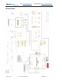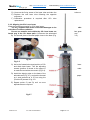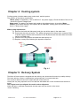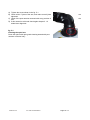
1
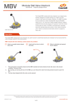
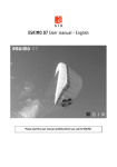
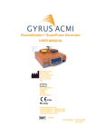
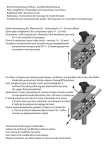
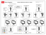
HQ: www.mediclase.com
Mediclase
Asia Marketing: www.mediclaseint.com
Healing by Light
Model: Miran
Superpulse
CO2 LASER SURGICAL SYSTEM
Mediclase Ltd
ALL RIGHTS RESERVED
Page 1 / 17
HQ: www.mediclase.com
Mediclase
Asia Marketing: www.mediclaseint.com
Healing by Light
CAUTION
Use of controls, adjustments or performance of procedures other than those specified in this user
manual may result in hazardous radiation exposure.
SPECIFICATIONS SUBJECT TO CHANGE
WTHOUT NOTICE
Version 1.0
General information:
The following chapters of this user manual contain the maintenance, troubleshooting and repairing
of principal parts of the Miran 25 CO2 Surgical Laser System. The person servicing the Miran 25
must be thoroughly familiar with the contents of this manual.
Service
This manual has been prepared to aid authorized technical personnel to understand and service the
Miran CO2 Laser system.
Special tools required: CO2 Power meter
Diode laser aligning tool
Delivery system aligning tool
Mediclase Ltd
ALL RIGHTS RESERVED
Page 2 / 17
HQ: www.mediclase.com
Mediclase
Asia Marketing: www.mediclaseint.com
Healing by Light
Components Position:
1. Control system: LCD control PCB and Main board
2. Power supply: HV laser power supply and low power supply
3. Cooling system: water pump, water tank, water sensor, fan
4. Laser source: Diode laser and CO2 laser
5. Optic and delivery system
Mediclase Ltd
ALL RIGHTS RESERVED
Page 3 / 17
HQ: www.mediclase.com
Mediclase
Asia Marketing: www.mediclaseint.com
Healing by Light
Wiring diagram
Mediclase Ltd
ALL RIGHTS RESERVED
Page 4 / 17
HQ: www.mediclase.com
Mediclase
Asia Marketing: www.mediclaseint.com
Healing by Light
Chapter 1: Control system
The main board administrates all the controls and commands of the system. The chips and the
connections designed for interfacing with the other electronics, and with the rest of the system.
Fig. 1.1
1.1_ Connections description:
Conn. J1 – power supply
Low power supply P 9 - 5V
P11, 12 – GND
P 1 – 12V
P 2 - -12V
High power supply
P6, P14, P8, P7, P15
Conn. J2 – Mechanics
P1 - Footswitch
P2 – Footswitch
P9 – Footswitch
P3 – Water sensor
P10 – Water sensor
P4 – Interlock
P11 – Interlock
P7 – Diode laser – P14 – Diode laser
+
P6- Diode lamp – P13 – Diode lamp
+
P8 – Resistor for aiming beam density adjustment
P15 – Resistor for aiming beam density adjustment
Conn. J5
Mediclase Ltd
ALL RIGHTS RESERVED
Page 5 / 17
HQ: www.mediclase.com
Mediclase
Asia Marketing: www.mediclaseint.com
Healing by Light
P1 – Pump
P3 – High power supply
Conn. J6 LCD
Conn. J7 Key board Conn. J8 Software
downloads
1.2. Controller Replacement
Main board replacement
A) Unplug connector J6 on the main board
B) Unscrew the main board from the unit.
C) Calibration procedures are required after the main board replacement.
LCD board replacement
A) Unplug connector J 202 on the LCD Board.
B) Unscrew the LCD board from the unit.
C) Calibration procedures are not required after LCD board replacement.
1.3. Calibration procedures
A)
B)
C)
D)
E)
F)
G)
Remove the handpieces from the articulated arm.
Ensure the CO2 laser beam enters the power meter.
Switch on the system.
Set the laser operation mode in CW mode and tissue exposure mode in Continuous.
Press "READY" key
Press "CALIBRATE" Key for seconds and the system display as follows.
Press "SELECT" Key, the cursor will move to the right side of Power value that is about to
calibrate.
H) Press "MODE" key, and move the cursor to the "DATA list", press UP and DOWN key to
calibrate the data unit. The power value that is displayed on the power meter equals to the
calibrating power.
I) Press "SELECT" Key and move to the next power value calibration needs. The procedures
are as above.
J) After all the power value calibration steps, press the "SAVE" key to store all the data.
Mediclase Ltd
ALL RIGHTS RESERVED
Page 6 / 17
HQ: www.mediclase.com
Mediclase
Asia Marketing: www.mediclaseint.com
Healing by Light
LASER OPERATION MODE: CW
_
POWER
0.5W
1W
2W
3W
4W
5W
6W
7W
8W
DATA
10
15
20
25
30
35
40
45
50
CALIBRATION
Note:
Moving the cursor up or down by pressing the SELECT key.
Moving the cursor left or right by pressing the MODE key.
Mediclase Ltd
ALL RIGHTS RESERVED
Page 7 / 17
HQ: www.mediclase.com
Mediclase
Asia Marketing: www.mediclaseint.com
Healing by Light
Chapter 2: Power supply
The Miran 25 CO2 Surgical Laser system can be operated either at 220V A.C. or 110V A.C.
Changing operating voltage cannot be performed.
Power supply of Miran 25 CO2 Surgical Laser includes: A) Low voltage
power supply
B) H.V. laser power supply
2.1 Low power supply
Caution:
High voltage inside.
Do not remove the cover of the low power supply!
AC Input: 220V _ 20% (Fig. 2.1)
110V _ 20% (Fig. 2.2)
Fig. 2.1
Fig. 2.2
DC Output:
V1: 5V 3.0A
V2: 12V 1.0 A
V3: -12V 0.5A
2.2 H.V. Laser power supply
Mediclase Ltd
ALL RIGHTS RESERVED
Page 8 / 17
HQ: www.mediclase.com
Mediclase
Asia Marketing: www.mediclaseint.com
Healing by Light
Lay out of the power supply
Mediclase Ltd
ALL RIGHTS RESERVED
Page 9 / 17
HQ: www.mediclase.com
Mediclase
Asia Marketing: www.mediclaseint.com
Healing by Light
2.2.1. Testing point (+12V) of the power supply is indicated in the following diagram
2.2.2. Power supply replacement (Fig. 2. 3):
Mediclase Ltd
ALL RIGHTS RESERVED
Page 10 / 17
HQ: www.mediclase.com
Mediclase
Asia Marketing: www.mediclaseint.com
Healing by Light
Fig. 2. 3
Power supply replacement Procedure: A) Switch off
the system.
B) Cut the connections of laser tube. Yellow wire connects the cathode of the laser tube. Red
wire connects the anode of the laser tube.
Warning:
The anodes of CO2 laser tube contain high voltage.
Electric shock hazard.
Never touch the anodes unless discharged.
C) Unscrew the power supply board from the unit.
D) Calibration procedure is required after H.V. laser power supply replacement.
Refer to Chapter 1.3 for calibration procedures.
Mediclase Ltd
ALL RIGHTS RESERVED
Page 11 / 17
HQ: www.mediclase.com
Mediclase
Asia Marketing: www.mediclaseint.com
Healing by Light
Chapter 3: Laser source
3.1 Diode laser resource
In view of the invisible beam of the 10.6um CO2 laser, a visible red diode laser is emitted
coaxially with the CO2 laser to assist the operator to locate the laser beam conveniently.
Diode laser wavelength 650 nm max
3mW CW adjustable
3.1.1. Diode laser Replacement Procedure:
A) Remove the plastic cover of the unit, and
unscrew the base of the articulated arm,
including diode laser (Fig. 3.1)
B) Disconnect the diode laser from the unit, and
the diode laser out.
C) Place a new diode laser which is already
aligned.
take
F
fig. 3.1
3.1.2 The diode laser alignment procedures are as follow:
A) Supply 3V to the diode laser needs alignment. Put the diode laser into the tube with a cover
with a hole in the center as fig. 3.2, the aiming
beam lit.
B) Trim the adjusting screws (position A) to center
the
red beam (Fig.3.3).
C) Install the aligning tube on the tube; proceed
as in
B) but using the Position B screws of fig 3.3.
F
Fig. 3.2
Mediclase Ltd
ALL RIGHTS RESERVED
Page 12 / 17
HQ: www.mediclase.com
Mediclase
Asia Marketing: www.mediclaseint.com
Healing by Light
Fig. 3.3
Position
A
Position
B
D) Repeat points B) and C) until no more adjustments are needed
(Fig.3.4).
Fig. 3.4.
3.2 CO2 Laser source
The technician must wear the protection goggles for invisible radiation at 10.6 microns in Class 4.
In the operative conditions, the anode of the CO2 tube contains a 20,000 volts voltage. Such voltage
might be LETHAL.
The technician must never touch the anode of the CO2 tube with bare
hands or with metallic tools.
Risk of Death!
3.2.1. CO2 tube replacement
A) Remove the back panel and let out all the water in the system.
B) Desolder the wires and disconnect from the power supply. The yellow wire connects the
cathode of the laser tube. Red wire connects the anode of the laser tube.
Warning:
The anodes of CO2 laser tube are under high voltage.
Electric shock hazard.
Never touch the anodes unless discharged.
C) Disconnect the two tubes of the cooling circuit; Pay special attention at the one at anode
side.
Mediclase Ltd
ALL RIGHTS RESERVED
Page 13 / 17
HQ: www.mediclase.com
Mediclase
Asia Marketing: www.mediclaseint.com
Healing by Light
D) Unscrew the fixing screw of the laser tube and take the
E) Replace the new laser tube following the opposite
sequence.
F) Calibration procedure is required after CO2 tube
replacement.
tube out.
3.2.2. Aligning the CO2 Laser beam
Wear the protection goggles for CO2 laser beam.
The CO2 radiation can cause irreversible damages to the
with direct or diffuse radiation.
Do not use metallic tools within the CO2 laser beam nor
hands stay in the CO2 beam path. A) Remove the articulated
B) Put a small piece of thermal paper close to the base (Fig.
skin
let your
arm.
3.5)
Fig.3.6
Fig. 3.5
C) Active the footswitch mutual position of CO2
and diode laser beam. Trim the adjusting
screws (position A) closer to the output in
to make the two beams concentric (Fig.3.6).
laser
order
D) Install the aligning tube on the base of the
articulate arm (Fig. 3.7), and put the thermal
on it and proceed as in C) but using the
(Position B) screws of fig. 3.6.
paper
E) Repeat points C) and D) until no more
adjustments are required.
Fig.3.7
Mediclase Ltd
ALL RIGHTS RESERVED
Page 14 / 17
Chapter 4: Cooling system
Cooling system includes water pump, water tank, and air system.
The position of the above components:
Water pump: is supplied by 110V or 220V A.C. net power supply. Check the label of the unit to
ensure the correct voltage input.
Water tank: The water in the water tank needs to be replaced every six months. Water
sensor: gives audio warning if the system lack of water Air: mainly gives out the heat from
the H.V. laser power supply.
Water pump replacement
C) Remove the back and side panel, and give out all the water in the water tank.
D) Disconnect the wires of pump. The yellow wire ground; the brown wire connects C24-L
of power supply; the blue wire connects C24-N. E) Disconnect the water tube from water
sensor and water tank.
F) Unscrew the fixing screws and take the water pump out.
G) Replace a new pump following the opposite sequence.
Fig. 4.1
Chapter 5: Delivery System
The Miran 25 laser system is wrapped with the delivery arm demounted for ensuring a safety delivery.
The beam delivery system is a lightweight, spring-balanced 7-joint articulated arm.
The connector base is fixed on the output terminal of the laser unit.
Usually the only thing required to do is to install the articulated arm on the connector base and lock it
tightly.
The surgical arm is pre-aligned. No need for mirror alignment.
When the laser is improper transported, the laser spot may not remain in the center.
Do the Following:
Mediclase Ltd
ALL RIGHTS RESERVED
Page 15 / 17
A) Tighten the screw shown in the fig. 5.1.
B) Check all the 7 joints of the arm, and make sure all joints
tightened.
C) Check if the spot remains centered with every position of
arm.
D) If this cannot be achieved check again chapter 3.1.2.
diode laser alignment.
are
the
fig. 5.1.
Cleaning the optic lens
Clean the optics with optic grade cleaning wetted with pure
acetone or ethanol only.
Mediclase Ltd
ALL RIGHTS RESERVED
Page 16 / 17
Chapter 6: Troubleshooting
Symptom
No switch on
The display does not
light up
Water pump does not
rotate
No aiming beam
No laser emits
No laser emits
No laser emits
No laser emits
No laser emission
Mediclase Ltd
Condition
Key switch turned on
Verify that
A) There is a correct connection of the plug in the
system’s inlet, and in the main plug. The red
main switch is turned on.
B) Emergency switch turned upwards. The inlet
plug’s fuses are O.K. The right voltage is
present in the main plug.
Key
switch on,
A) Perfect connection of J1
emergency switch on,
B) The presence of 5V between P9 and P11 of
J1
pump rotated
C) Replacement of display board
Key
switch
on, A) The correct voltage (220V A.C.) in
emergency switch
B) Deflation from the pump.
On, keyboard lit
C) Mechanical problem in the pump itself
Key
switch on,
A) Perfect connection of J2
emergency switch on,
B) The presence of 3V between P7 and P14 of
J2
keyboard lit on
C) Replacement of new Diode laser
Key
switch on,
A) Perfect connection of J2
emergency switch on,
B) Perfect connection between J1-P6, P14 of
keyboard lit on
control board and CZ1 of power supply;
between J1-P7, P15 and CZ3 of power
supply
Above condition met
A) Laser beam Alignment to avoid emitting to the
wall of articulate arm (refer to chapter 5)
Above condition met
A) Activity of shutter in the front of laser tube
aperture once the footswitch stepped.
B) No crack on the laser tube
C) Presence of laser light in laser tube once
footswitch stepped.
D) Replacement of laser tube
Above condition met
A) The presence of normal data according to all
the power value in Calibration mode
B) Calibration and raise the data (refer to chapter
1.3.)
Above condition met
A) The presence of 12V on the testing point of
power supply (see chapter 2.2.2)
ALL RIGHTS RESERVED
Page 17 / 17