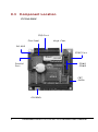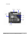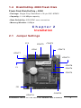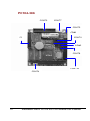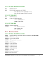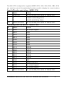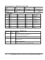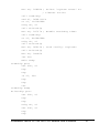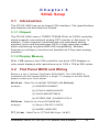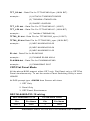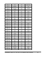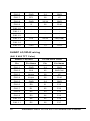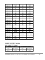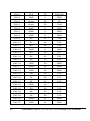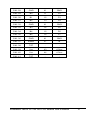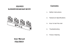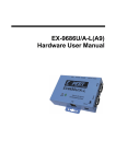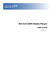
1
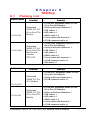
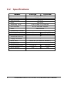
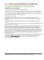
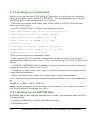
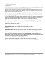
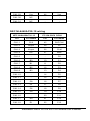
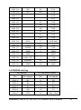
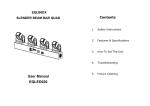
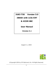
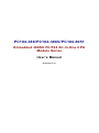
PC104-386/PC104-386V/PC104-6051 Embedded 386SX PC/104 All-in-One CPU Module Series User’s Manual (Version 3.1) Copyright Notice This document is copyrighted, 2000 by Nagasaki International Corp. All rights are reserved. The information in the manual is subject to change without notice in order to improving products. No part of this manual may be reproduced, copied, translated or transmitted in any form or by any means without the prior written permission of the manufacturer. Nagasaki International Corp. assumes no responsibility for any inaccuracies that may be contained in this document. Nagasaki International Corp. makes no commitment to update or to keep current the information contained in this manual. Copyright 2000 by Nagasaki International Corp. All rights reserved. Ver.2.1 2000, Printed in Taiwan Trademarks Acknowledgments All brand names and trademarks are the properties and registered brands of their respective owners. ii Table of Contents Chapter 0 0.1 0.2 0.3 Chapter 1 1.1 1.2 1.3 1.4 Introduction Features ..................................................................... 6 Specifications ............................................................ 7 VGA Interface............................................................. 8 DiskOnChip ................................................................ 9 Chapter 2 2.1 Startup Packing List ............................................................... 1 Specifications ............................................................ 1 Component Location ................................................. 3 Installation Jumper Settings......................................................... 9 2.1.1 PC104-386V ..................................................... 11 2.1.2 PC104-3026 PC104-386V-4M PC104-3610 PC104-6051 ....................................................................... 11 2.1.3 PC104-386 ....................................................... 11 2.2 Connectors .............................................................. 11 2.2.1 PC104-386V ..................................................... 11 2.2.2 PC104-6051 ..................................................... 12 2.2.3 PC104-386 ....................................................... 12 2.3 DiskOnChip/EPROM/Flash ROM Disk ...................... 13 2.3.1 Setting Up a DiskOnChip 2000 Flah Disk........ 13 2.3.2 Setting Up a Flash Disk................................... 14 2.3.3 Setting Up an EPROM Disk ............................. 14 2.4 Watchdog Timer ....................................................... 16 Chapter 3 3.1 3.2 SVGA Setup Introduction ............................................................. 23 3.1.1 Chipset ............................................................ 23 3.1.2 Display Memory............................................... 23 Flat Panel BIOS and Wiring ..................................... 23 Warranty iii Chapter 0 Startup 0.1 Packing List Product Name PC104-386 PC104-386V Product Name Function Package l PC104-386 Embedded 386SX PC/104 Aii-in-One CPU Module Embedded l Utility and Drivers Diskette x 1 386SX PC/104 l FDD cable x 1 All-in-One CPU l HDD cable x 1 Module l RS232 cable x 2 l Printer cable with bracket x 1 l AT KB connector cable x 1 l PC104-386V Embedded 386SX PC/104 All-in-One CPU Module Embedded l Utility and Drivers Diskette x 1 386SX PC/104 l FDD cable x 1 All-in-One CPU l HDD cable x 1 Module with onboard l RS232 cable x 2 CRT/LCD l Printer cable with bracket x 1 l AT KB connector cable x 1 l VGA cable x 1 Function Embedded 386SX PC/104 CPU Module Package l PC104-6051 Embedded 386SX PC/104 All-in-One CPU Module l Utility and Drivers Diskette x 1 l AT KB connector cable x 1 PC104-6051 PC104-386 l PC104-386 Embedded 386SX PC/104 All-in-One CPU Module Embedded l Utility and Drivers Diskette x 1 386SX PC/104 All-in-One CPU l FDD cable x 1 l HDD cable x 1 Module l RS232 cable x 2 l Printer cable with bracket x 1 l AT KB connector cable x 1 Embedded 386SX PC/104 AIO CPU Module User's Manual 1 0.2 Specifications Features PC104-386 DM&P(ALi) M6117D Chipset 386SX-40 on-die Processor Multi I/O Chip ALi 5113 BIOS AMI BIOS Watchdog Timer Bus Interface From 30.5µs to 512 seconds PC/104 standard compliant 4MB onboard RAM 1 DiskOnChip Sockets Display X VGA/LCD VGA CRT/LCD Chip X TOPRO TP65081Q Enhanced IDE Port 1 Floppy Connector 1 Serial Port RS232 X 2 (or RS232x1,RS485x1) 1 Parallel Port Power Requirement Board Weight Board Size 2 PC104-386V +5V @0.8A +5V @1A 105g 130g 90mm x 96mm Embedded 386SX PC/104 AIO CPU Module User's Manual Features PC104-386 PC104-6051 DM&P(ALi) M6117D Chipset 386SX-40 on-die Processor Multi I/O Chip ALi 5113 BIOS AMI BIOS Watchdog Timer Bus Interface From 30.5µs to 512 seconds PC/104 standard compliant 4MB onboard RAM Display X Enhanced IDE Port 1 Floppy Connector 1 X Flash Disk / DiskOnChip Socket 1 x Flash Disk / EPROM Socket x 2 RS232 X 2 X 1 X Serial Port Parallel Port Power Requirement Board Weight Board Size +5V @0.8A +5V @0.6A 105g 90mm x 96mm Embedded 386SX PC/104 AIO CPU Module User's Manual 3 0.3 Component Location PC104-386V FDD Port Flat Panel Keyb. Cont. RS-485 EIDE Port Parallel Port COM1 COM2 CRT SVGA +5V/GND 4 Embedded 386SX PC/104 AIO CPU Module User's Manual PC104-386 FDD Port Keyb. Cont. Parallel Port COM1 COM2 EIDE Port +5V/GND Embedded 386SX PC/104 AIO CPU Module User's Manual 5 Chapter 1 Introduction 1.1 Features The contains all standard motherboard features such as : 386SX-40 compatible CPU, 4 MB DRAM onboard, CRT and Flat Panel SVGA controller, serial and parallel ports, floppy and EIDE disk controller. The SSD modules' socket can accommodate a DiskOnChip ® 2000, a new generation of high performance single-chip Flash Disks of up to 144 MB. The ICOP-605X is a core module for high performance control applications in demanding embedded applications. Because the module implements all key functions of a full PC/AT compatible system any standard PC compiler or debugger can be used, resultng in a significantly reduced software develop-ment cycle. I/O and Enhanced IDE In addition, the 605X has one PS/2 mouse port, two serial ports (RS-232 and/or RS-485), one bidirectional printer port that supports SPP, ECP andEPP modes, an enhanced IDE HDD interface that supports PIO mode 4, and a floppy disk controller. Flash or EPROM Disk or DiskOnChip The onboard socket can accept up to 2 MB EPROM (PC104-6051) or 1 MB Flash memory. Both sockets can by jumper setting be assigned to hold a DiskOnChip. There areno combinations possible of devices, it is either Flash, EPROM or DiskOn-Chip. Watchdog Timer The watchdog timer optionally monitors system operation and can invoke asystem reset when your application loses control over the system. The timing of the watchdog timer is programmable by software. 6 Embedded 386SX PC/104 AIO CPU Module User's Manual 1.2 Specifications • Embedded CPU: DM&P(ALi) M6117D is an implementation of an INTEL compatible 386SX-40 CPU, Realtime clock, a watchdog timer and ALi’s M1217B chipset • BIOS: Y2K compliant AMI system BIOS • DRAM Memory: 4MB EDO DRAM onboard • Bus Interface: PC/104 • Data Bus: 16-bit • Bus Speeds: PC/104 - 8 MHz (above values are defaults, bus speeds are programmable up to 16 MHz) • DMA Channels: 7 • Interrupt Levels: 15 • Enhanced IDE: supports one port and up to two hard drives or Enhanced IDE devices of PIO mode 4. BIOS enabled/disabled • Watchdog Timer: generates either a RESET, NMI or an IRQ when your application loses control over the system. Optionally the watchdog can trigger a user specified interrupt. The watchdog is configurable from 30.5 µs to 512 seconds (in 30.5 µs segments) • Real-time Clock: included in M6117D with onboard lithium battery backup for 10 years of data retention. CMOS data backup of BIOS setup and BIOS default. • Keyboard and Mouse Connectors: Internal 5-pin header for AT-keyboard Internal 5-pin header for PS/2-mouse High Speed Multi I/O • Chipset: ALi 5113 or SMS CFDC37C669 • Serial ports: one high speed RS-232 port, one high speed RS-232/485 port (jumper selectable). Both with 16C550 UART and 16 byte FIFO. BIOS enabled/ disabled • Floppy Disk Drive Interface: supports up to two floppy drives, 5¼ “ (360 KB or 1.2 MB) and 3½ “ (720 KB, 1.44 MB). BIOS enabled / disabled • Bi-directional Parallel Port: supports SPP, EPP and ECP mode. BIOS enabled/disabled Environmental and Power • Power Requirements: single voltage +5 V Embedded 386SX PC/104 AIO CPU Module User's Manual 7 • Board Dimensions: 90 (L) x 96 (W) mm. • Board Weight: 105 g • Extended Operating Temperature: -20~+60 °C 1.3 VGA Interface (PC104-386V) • Chipset: TOPRO TP65081Q • Memory: 1 MB onboard • System Bus: 16-bit ISA bus • Panel Data Bus: 24-bit • Display: CRT and Flat Panel Mono/TFT/DSTN/EL • Supported Flat Panels: NEC NL-6448AC30-10 TFT 9.4" 640X480 NEC NL-6448AC30-03 TFT 9.4" 640X480 NEC NL-6448AC33-10 TFT 10.4" 640X480 NEC NL-6448AC33-13 TFT 10.4" 640X480 NEC NL-6448AC33-18 TFT 10.4" 640X480 NEC NL-8060BC31-09 TFT 12’1 800X600 NEC NL-8060AC31-02 TFT 10.4" 800X600 NEC NL-8060AC31-01 TFT 10.4" 800X600 SHARP LQ10D42 TFT 10.4" 640X480 SHARP LQ10D421 TFT 10.4" 640X480 SHARP LQ12531 TFT 12.1" 800x600 SHARP LM64C35P MONO 10.4" 640X480 Planar EL640.480-AA1 EL color 10.4" 640X480 8 Embedded 386SX PC/104 AIO CPU Module User's Manual 1.4 DiskOnChip 2000 Flash Disk Flash Disk DiskOnChip ® 2000 • Package: Single Chip FlashDisk in 32-pin DIP JEDEC • Capacity: 1-144 MByte capacity • Data Reliability: ECC/EDC error correction • Memory Window: 8 KByte Chapter 2 Installation 2.1 Jumper Settings JP2 CONT5 CON1 CONT3 CONT9 CONT7 CONT11 CONT8 CONT6 P1 CONT4 JP1 CONT10 CONT12 Embedded 386SX PC/104 AIO CPU Module User's Manual 9 PC104-386 CONT9 CONT7 CONT5 COM1 P1 CONT4 COM2 CONT8 CONT10 CONT6 10 Embedded 386SX PC/104 AIO CPU Module User's Manual 2.1.1 PC104-386/PC104-386V JP1 RESET Switch JP2 RS-232/485 selection for COM2 1-2: RS-232 mode (CONT6 active) 2-3: RS-485 mode (CONT7 active) 2.1.2 PC104-6051 JP1 RESET Switch JP2 Flash / EPROM slection close: EPROM Disk open: Flash Disk 2.1.2 PC104-386 CONT6 Power connector CONT8 1-2: RESET SWITCH 3-4: Power LED 5-6: IDE LED 2.2 Connectors 2.2.1 PC104-386/PC104-386V CON1 Internal 44-pin Flat Panel SVGA connector (PC104-386V) CONT1 PC/104 bus 64-pin CONT2 PC/104 bus 40-pin CONT3 AT-keyboard connector CONT4 PS/2 Mouse CONT5 FDD controller CONT6 COM2 RS-232 CONT7 COM2 RS-485 CONT8 COM1 RS-232 CONT9 IDE LED CONT10 Power Connector CONT11 IDE connector Embedded 386SX PC/104 AIO CPU Module User's Manual 11 CONT12 CRT SVGA connector P1 Parallel Port 2.2.2 PC104-6051 CONT1 PC/104 bus 64-pin CONT2 PC/104 bus 40-pin CN3 Keyboard Connector SP1 External Speaker U13 Socket for Flash/EPROM Disk U14 Socket for Flash/EPROM Disk 2.2.2 PC104-386 CONT2 PC/104 bus 64-pin CONT3 PC/104 bus 40-pin CONT4 PS/2 Mouse CONT5 Speaker Connector CONT7 Keyboard Connector CONT9 FDD controller CONT10 IDE connector COM1 COM1 RS-232 COM2 COM2 RS-232 P1 Parallel Port 12 Embedded 386SX PC/104 AIO CPU Module User's Manual 2.3 DiskOnChip/EPROM/Flash ROM Disk 2.3.1 Setup a DiskOnChip ® 2000 Flash Disk Installation Instructions 1. Make sure the ICOP-605X is powered OFF 2. Plug the DiskOnChip 2000 device(s) into its socket. Verify the direction is correct (pin 1 of the DiskOnChip 2000 is aligned with pin 1 of the socket) 3. Set address for both DiskOnChip devices (note that the last two settings are for normal EPROM or Flash devices) 4. Power up the system 5. During power up you may observe the messages displayed by the DiskOnChip 2000 when its drivers are automatically loaded into system’s memory 6. At this stage the DiskOnChip 2000 can be accessed as any disk in the system 7. If the DiskOnChip 2000 is the only disk in the system, it will appear as the first disk (drive C: in DOS) 8. If there are more disks besides the DiskOnChip 2000, the DiskOnChip 2000 will appear by default as the last drive, unless it was programmed as first drive. (please refer to the DiskOnChip 2000 utilities user manual) 9. If you want the DiskOnChip 2000 to be bootable: a - copy the operating system files into the DiskOnChip by using the standard DOS command (for example: sys d:) b - The DiskOnChip should be the only disk in the systems or should be configured as the first disk in the system (c: ) using the DUPDATE utility For more information on DiskOnChip2000 technology, visit M-Systems Web site http:// www.m-sys.com where you can find Utilities Manual, Data Sheets and Application Notes. In addition, you can find the lasted DiskOnChip 2000 S/W Utilities. Embedded 386SX PC/104 AIO CPU Module User's Manual 13 2.3.2 Setting up a Flash Disk Before you can use the ICOP-605X’s Flash disk you will have to initialize it using a software utility called “PC104.EXE”. This program can be found on the utility disk in the subdirectory “A:\FLASH” - Connect a keyboard and floppy disk ICOP-605X to the PC/104 bus and boot-up your system. - run PC104.EXE (this is a DOS command line utility) ICOP-605X FLASH disk initialize program V1.0 FLASH manufacturer : (1)ATMEL (2)SST Input manufacturer number (1,2) : 1 Input quantity of FLASH (1,2) : 2 Simulation disk: (1)DISK-A (2)DISK-B (3)DISK-C (4)DISK-D Input manufacturer number (1,2,3,4) : 1 FLASH-DISK initialize finish. (Text in bold should be entered by user) - After running the PC104.EXE configuration program reboot the system, while holding down the left “CRTL” key. This will bring you to the “Flash Disk Utility” - “CHANGE CURRENT DISK NUMBER” lets you select the drive you want to assign to the disk, either A, B, C or D - “CHANGE FLASH DISK SIZE” lets you select the amount of Flash EPROM chips that are onboard. - make selections and reboot the system after closing the program Your disk can now be formatted and setup with normal DOS commands such as FORMAT, FDISK, COPY, SYS etc. Note : when assigning the solid state disk as either C or D, you first have to run FDISK before formatting the drive ! 2.3.3 Setting up an EPROM Disk EPROMs should be inserted starting from Socket. All modules have to be of the same type. To create a ROM disk you will need the following: - EPROM devices 14 Embedded 386SX PC/104 AIO CPU Module User's Manual - EPROM programmer - ROM files The ROM files are hacked-up portions of your system and program files that should have the same size as your EPROM devices. On the utility disk you will find a program called: ROMIMAGE.EXE that will assist you in creating these files. Before using the program there are some files you will have to prepare first: 1. The system files, for example MSDOS.SYS, I/O.SYS, COMMAND.COM The program can pick these files up automatically from your boot deviceor from a bootable floppy. 2. Your application files and other necessary DOS files. Make a subdirectory that only contains these additional files. With “other DOS files” are meant files such as AUTOEXEC.BAT, CONFIG.SYS, EMM386.EXE etc 3. Prepare a directory that can temporarily hold the generated ROM files Once you prepared all the above, start the ROMIMAGE.EXE programSystem driver : location of system files (see 1) Source path: location of program files (see 2) Destination path: this is where the ROM files go (see 3) EPROM-size: depends on your choice Simulation-disk: set this to the drive letter the ROM disk should emulate After you have set all the right directories, use the Analysis file function to let the program determine how many files of what size it should generate. After using the Analysis function go to Create image, and generate the ROM files. Than exit the program. In the directory that was assigned to hold the ROM files you will find your ROM images: For example: ROM010.01 ROM010.02 Use an EPROM programmer to write the files to their EPROMs. Beware to keep track of their sequence when inserting the EPROM’s PRESS ESC KEY QUIT THIS PROGRAM Embedded 386SX PC/104 AIO CPU Module User's Manual 15 2.4 Watchdog Timer The watchdog timer uses a 32.768 KHz frequency source with a 24-bit counter. Its time range stretches from 30.5 ms to 512 sec. with a resolution of 30.5 ms. When the watchdog times out a System RESET, NMI or IRQ can be invoked. Watchdog timer control and the 24-bit counter itself occupy 6 consecutive 8-bit address locations. When functioning properly the system resets the watchdog timer periodically to prohibit that it times out. If the watchdog timer times out, it will RESET the system, or generate and NMI or IRQ, depending on its configuration. Watchdog or System Timer Another great application is to generate a periodic IRQ signal. Under DOS environment, the 8254, system timer 0, will generate IRQ0 every 54.9 ms. The watchdog is like system timer 0. It can be programmed to periodically generate a configurable IRQ. It may be clear that the selected IRQ, will be no longer available to the system. Configuring the Watchdog Timer in the BIOS The M6117D watchdog configuration register can be controlled by software or can be setup in the BIOS. To do so go to BIOS Setup’s “Advanched Chipset Setup” Watchdog Function = Enable/Disable Watchdog Signal = RESET, NMI or IRQ 3/4/5/6/7/9/10/11/12/14/15 Watchdog Timer = 1/2/4/8/16/32/64/128/256/512 Seconds The BIOS setup only offers a limited amount of time-out values. More a hiher resolution of timeout values refer to the next paragraph “Configuring the Watchdog Timer by Software” Note that in case of using the BIOS setup, the watchdog starts counting the moment it passes the BIOS setup. This means that if you set the time-out period to 1 second, the system will keep rebooting before being able to load operating system or software ! After you have finnished configuring you watchdog timer read “Timeout Status & Reset - INDEX 3CH” on page 12 and look at the example on page 15 to find out how to priodically reseting the timeout status to prevent the watchdog timer from invoking a RESET, NMI or IRQ. Configuring the Watchdog Timer by Software Chipset configuration registers 16 Embedded 386SX PC/104 AIO CPU Module User's Manual The M6117D configuration register INDEX 37H, 38H, 39H, 3AH, 3BH, 3Ch are used to control the watchdog functions and/or display its current status. Enable/Disable watchdog - INDEX 37H Bit Value Action 7 reserved Do not modify the value of these bits! 6 0 Disable watchdog timer 1 Enable watchdog timer Other function Do not modify the value of these bits! 5-0 Watchdog time out action - INDEX 38H Bit Value Action 7-4 0000 No output signal 0001 IRQ3 0010 IRQ4 0011 IRQ5 0100 IRQ6 0101 IRQ7 0110 IRQ9 0111 IRQ10 1000 IRQ11 1001 IRQ12 1010 IRQ14 1011 IRQ15 1100 NMI 1101 System RESET 1110 No output signal 1111 No output signal Other function Do not modify the value of these bits! 3-0 Embedded 386SX PC/104 AIO CPU Module User's Manual 17 Watchdog timer - INDEX 39H, 3AH, 3BH Index 3Bh 3Ah 39h Bits D7… … D0 D7… … D0 D7… … D0 counter [VSB… … … … … . … … … … … … … ... … … … ..LSB] For example Index 3Bh 3Ah 39h Time out 00h 00h 01h 30.5µ s 00h 00h 02h 61µ s 00h 01h 00h 7.8 ms 00h 02h 00h 15.6 ms 01h 00h 00h 2s 02h 00h 00h 4s FFh FFh FFh 512 s Timeout Status & Reset - INDEX 3CH Bit Value Action 7 0 Timeout has not occurred 1 Timeout has occured 1 Reset timer 0 Has no meaning 6 5 4-0 18 Other function, do not modify these bits Embedded 386SX PC/104 AIO CPU Module User's Manual Programming the watchdog To perform any operation on the M6117D configuration registers you always have to unlock first and lock the registers afterwards Unlock configuration register Lock configuration register mov al, 013h mov al, 013h out 22h, al out 22h, al nop nop nop nop mov al, 0c5h mov al, 000h out 23h, al out 23h, al nop nop nop nop Read the value of a configuration register For example, read INDEX 3Ch : Unlock configuration register mov al, 03ch out 22h, al nop nop in al, 23h nop nop push ax Lock configuration register pop ax ;AL - result Write data to configuration register For example, write 0FFh to INDEX 3Bh : Unlock configuration register mov al, 03bh out 22h, al nop nop mov al, 0ffh out 23h, al Embedded 386SX PC/104 AIO CPU Module User's Manual 19 nop nop Lock configuration register Watchdog Program Example We use the following sequence to initialize the watchdog timer: (1) Unlock configuration register. (2) Disable watchdog timer by setting INDEX 37H Bit 6 to ‘0’. (3) Set the expected counter value to INDEX 3BH, 3AH, 39H. (4) Select timeout action from INDEX 38H Bit 7-4. (5) Enable watchdog timer by setting INDEX 37H Bit 6 to ‘1’. (6) Lock configuration register. Example: Set timeout to 128 sec to generate a system RESET. ; Please use MASM to compiler the following program ; Execute under DOS environment dosseg . model small . stack 100h .code main proc mov ax, 0c513h ; Unlock config. register call writechip mov ax, 03737h ; Disable watchdog timer call readchip and al, 10111111b xchg ah, al call writechip mov ax, 0403bh ; Set the expected counter ; value call writechip ; to [400000h] mov ax, 0003ah ; 30.5*sec*400000h= 128 sec call writechip mov ax, 00039h call writechip 20 Embedded 386SX PC/104 AIO CPU Module User's Manual mov ax, 03838h ; Select “system reset” as ; timeout action call readchip and al, 00001111b or al, 11010000b xchg ah, al call writechip mov ax, 03737h ; Enable watchdog timer call readchip or al, 01000000b xchg ah, al call writechip mov ax, 00013h ; Lock config. register call writechip mov ax, 04c00h int 21h main endp readchip proc out 22h, al nop nop in al, 23h nop nop ret readchip endp writechip proc out 22h, al nop nop xchg ah, al out 23h, al nop nop Embedded 386SX PC/104 AIO CPU Module User's Manual 21 xchg ah, al ret writechip endp end main Reset watchdog timer Resets the watchdog timer periodically to prevent timeout. mov ax, 0c513h ; Unlock configuration ; register call writechip mov ax, 03C3Ch ; Reset watchdog timer ; counter call readchip or al, 00100000b ; The counter is reset at xchg ah, al ; out 23h, al call writechip mov ax, 00013h ; Lock configuration ; register call writechip (the above code uses readchip and writechip procedures) 22 Embedded 386SX PC/104 AIO CPU Module User's Manual Chapter 3 SVGA Setup 3.1 Introduction The PC104-386V has an on-board VGA interface. The specifications and features are described as follows: 3.1.1 Chipset The PC104-386V uses a TOPRO TP65081Q for its SVGA controller, which supports conventional analog CRT monitor or flat panel. In addition, it also supports interlaced and non-interlaced analog monitors (color and monochrome VGA) in high-resolution modes while maintaining complete IBM VGA compatibility. Multiple frequency (multisync) monitors are handled as if they were analog monitors. 3.1.2 Display Memory With 1 MB memory, the VGA controller can drive CRT displays or color panel displays with resolutions up to 1024 x 768 at 256 colors. 3.2 Flat Panel BIOS and Wiring Below is a list of optional Flat Panel SVGA BIOS. The VGA BIOS is combined with the system BIOS in a single. To change to another BIOS please contact your local dealer. MLCD.dat - Data File for MONO DSTN640*480 (Default) example : (1) HOSIDEN HLM6667 (2) HITACHI LMG5160XUFC (3) CASIO MD650TS00-01 (4) OPTREX DMF_50260NFU-FW -8 DSTN.dat - Data file for Color DSTN640*480 example : (1) Sanyo LCM-5331-22NTK (2) SHARP LM64C35P TFT_S1.dat - Data File for TFT640*480-Sync (16 BIT) Embedded 386SX PC/104 AIO CPU Module User's Manual 23 TFT_S2.dat - Data File for TFT640*480-Sync (18/24 BIT) example : (1) HITACHI TX26D60/TX24D55 (2) TOSHIBA LTM09C015A (3) SHARP LQ10D321 TFT_LP1.dat - Data File For TFT640*480-LP (16 BIT) TFT_LP2.dat - Data File For TFT640*480-LP (18/24 BIT) example : (1) Toshiba LTM09c015A) TFT86_S1.dat - Data File for TFT800*600_sync (16 BIT) TFT86_S2.dat Data File for TFT800*600_sync (18/24 BIT) example : (1) NEC NL8060AC26-05 (2) NEC NL8060AC26-04 (3) NEC NL8060BC31-02 EL.dat - Data File for EL640*480 example : (1) PLANAR EL640.480-A PLASMA.dat - Data File for PLASMA640*480 example : (1) PANASONIC S817 CRT/Flat Panel Mode All the above BIOS support either CRT only, Flat Panel only or CRT/Flat Panel simultaneously. To set the mode a Panel Switching Utility is used. USAGE: At DOS prompt type >SW508 then Screen will show 1. CRT Only 2. Panel Only 3. CRT/Panel Simutaneous NEC NL6448AC33-18 wiring NEC NL6448AC33-18 24 PC104-386V CON1 Pin Pin Name Pin Pin Name CN1-1 GND 3 GND Embedded 386SX PC/104 AIO CPU Module User's Manual CN1-2 CLK 35 SHFCLK CN1-3 Hsync 38 LP CN1-4 Vsync 36 FLM CN1-5 GND 4 - CN1-6 R0 27 P18 CN1-7 R1 28 P19 CN1-8 R2 29 P20 CN1-9 R3 30 P21 CN1-10 R4 31 P22 CN1-11 R5 32 P23 CN1-12 GND 33 - CN1-13 G0 19 P10 CN1-14 G1 20 P11 CN1-15 G2 21 P12 CN1-16 G3 22 P13 CN1-17 G4 23 P14 CN1-18 G5 24 P15 CN1-19 GND 34 - CN1-20 B0 11 P2 CN1-21 B1 12 P3 CN1-22 B2 13 P4 CN1-23 B3 14 P5 CN1-24 B4 15 P6 CN1-25 B5 16 P7 CN1-26 GND 39 - CN1-27 ENAB 37 MDE CN1-28 Vcc 43 Vcc Embedded 386SX PC/104 AIO CPU Module User's Manual 25 CN1-29 Vcc 44 Vcc CN1-30 NC - - CN1-31 NC - - NEC NL6448AC30-10 wiring NEC NL6448AC30-10 26 PC104-386V CON1 Pin Pin Name Pin Pin Name CN1-1 CLK 42 SHFCLK CN1-2 Hsync 38 LP CN1-3 Vsync 36 FLM CN1-4 DE 37 MDE CN1-5 - - P0 CN1-6 B0 10 P1 CN1-7 B1 11 P2 CN1-8 B2 12 P3 CN1-9 B3 13 P4 CN1-10 - 14 P5 CN1-11 - 15 P6 CN1-12 G0 16 P7 CN1-13 G1 17 P8 CN1-14 G2 18 P9 CN1-15 G3 19 P10 CN1-16 - 20 P11 CN1-17 R0 21 P12 CN1-18 R1 22 P13 Embedded 386SX PC/104 AIO CPU Module User's Manual CN1-19 R2 23 P14 CN1-20 R3 24 P15 CN1-21 - - P16 CN1-22 - - P17 CN1-23 - 27 P18 CN1-24 - 28 P19 CN1-25 - 29 P20 CN1-26 - 30 P21 CN1-27 - 31 P22 CN1-28 - 32 P23 CN1-29 PVcc 5 LCD Vdd CN1-30 Vcc 43 Vcc CN1-31 MODE 44 Vcc CN1-32 GND 3 GND CN1-33 GND 4 GND CN1-34 Vdd +12 1 +12 CN1-35 ENABKL 40 ENABKL CN1-36 GND 39 GND LJ32H028 wiring LJ32H028 PC104-386V CON1 Pin Pin Name Pin Pin Name CN1-1 D1 11 P2 CN1-2 D0 12 P3 CN1-3 D3 9 P0 CN1-4 D2 10 P1 CN1-5 CP2 35 SHF_CLK Embedded 386SX PC/104 AIO CPU Module User's Manual 27 CN1-6 GND 3,4 GND CN1-7 CP1 38 LP CN1-8 GND 33,34 GND CN1-9 S 36 FLM CN1-10 - - - CN1-11 - - - CN1-12 - - - CN1-13 +5V 43,44 +5V(Vdd) CN1-14 - - - CN1-15 +12V 1,2 +12V SHARP LQ10D42 wiring (640 X 480 TFT Color) SHARP LQ10D42 28 PC104-386V CON1 Pin Pin Name Pin Pin Name CN1-1 GND 3,4 GND CN1-2 CLK 42 SHFCLK CN1-3 Hsync 38 LP CN1-4 Vsync 36 FLM CN1-5 GND 3,4 GND CN1-6 R0 21 P12 CN1-7 R1 22 P13 CN1-8 R2 23 P14 CN1-9 R3 24 P15 CN1-10 R4 25 P16 CN1-11 R5 26 P17 Embedded 386SX PC/104 AIO CPU Module User's Manual CN1-12 GND 3,4 GND CN1-13 G0 15 P6 CN1-14 G1 16 P7 CN1-15 G2 17 P8 CN1-16 G3 18 P9 CN1-17 G4 19 P10 CN1-18 G5 20 P11 CN1-19 GND 3,4 GND CN1-20 B0 9 P0 CN1-21 B1 10 P1 CN1-22 B2 11 P2 CN1-23 B3 12 P3 CN1-24 B4 13 P4 CN1-25 B5 14 P5 CN1-26 GND 3,4 GND CN1-27 ENAB 40 M CN1-28 Vcc 43,44 Vcc +5V CN1-29 Vcc 43,44 Vcc +5V CN1-30 R/L - - CN1-31 U/D - - SHARP LQ12S31 wiring (800 X 600 TFT Color) SHARP LQ12S31 PC104-386V CON1 Pin Pin Name Pin Pin Name CN1-1 GND 3 GND Embedded 386SX PC/104 AIO CPU Module User's Manual 29 30 CN1-2 CLK 35 SHFCLK CN1-3 GND 4 GND CN1-4 Hsync 38 LP CN1-5 Vsync 36 FLM CN1-6 GND 8 GND CN1-7 GND 8 GND CN1-8 GND 8 GND CN1-9 R0 27 P18 CN1-10 R1 28 P19 CN1-11 R2 29 P20 CN1-12 GND 8 GND CN1-13 R3 30 P21 CN1-14 R4 31 P22 CN1-15 R5 32 P23 CN1-16 GND 39 GND CN1-17 GND 39 GND CN1-18 GND 39 GND CN1-19 G0 19 P10 CN1-20 G1 20 P11 CN1-21 G2 21 P12 CN1-22 GND 39 CN1-23 G3 22 P13 CN1-24 G4 23 P14 CN1-25 G5 24 P15 CN1-26 GND 41 GND CN1-27 GND 41 GND Embedded 386SX PC/104 AIO CPU Module User's Manual CN1-28 GND 41 GND CN1-29 B0 11 P2 CN1-30 B1 12 P3 CN1-31 B2 13 P4 CN1-32 GND 41 GND CN1-33 B3 14 P5 CN1-34 B4 15 P6 CN1-35 B5 16 P7 CN1-36 GND 41 GND CN1-37 ENAR 37 M CN1-38 TST - - CN1-39 Vcc 43 +5Vcc CN1-40 Vcc 44 +5Vcc CN1-41 TST - - Embedded 386SX PC/104 AIO CPU Module User's Manual 31 Warranty This product is warranted to be in good working order for a period of one year from the date of purchase. Should this product fail to be in good working orderat any time during this period, we will, at our option, replace or repair it at noadditional charge except as set forth in the following terms. This warranty doesnot apply to products damaged by misuse, modifications, accident or disaster. Vendor assumes no liability for any damages, lost profits, lost savings or anyother incidental or consequential damage resulting from the use, misuse of, orinability to use this product. Vendor will not be liable for any claim made by anyother related party. Return authorization must be obtained from the vendor before returned merchandise will be accepted. Authorization can be obtained by calling or faxing the vendor and requesting a Return Merchandise Authorization (RMA) number. Returned goods should always be accompanied by a clear problem description. 32 Embedded 386SX PC/104 AIO CPU Module User's Manual