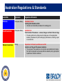
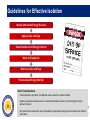
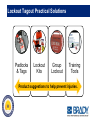
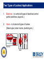
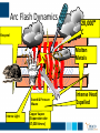
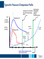
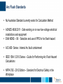
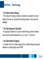
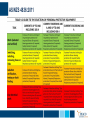
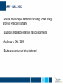
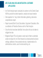
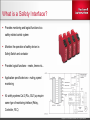
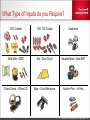
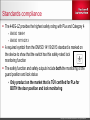
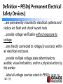
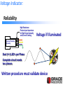
1
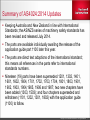
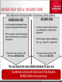
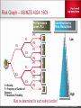
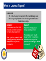
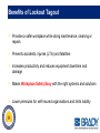
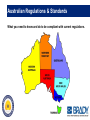
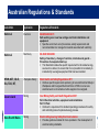
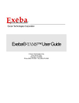
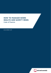
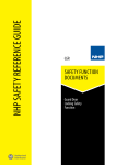
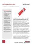
Machine and Plant Safety Seminar Agenda 1. Machine Safety Standards 9.00-9.30 2. Lockout Tagout 9.30-10.00 3. Arc Flash 10.00-10.30 Break 10.30-10.45 4. Integrated Safety Solutions 10.45-11.15 5.Safety Tools 11.15-11.45 Functional Safety Wayne Pearse Safety Consultant FSExpert (TÜV Rheinland, Machinery) FSEngineer (TÜV Rheinland, Machinery) Rev 5058-CO900D Copyright © 2013 Rockwell Automation, Inc. All Rights Reserved. Agenda 1. AS/NZS 4024:2014 Update 2. AS/NZS 4024:1503 (ISO 13849:2006) 3. Machine Safety / Functional Safety 4. TÜV Functional Safety Training 5. Safety Services Copyright © 2013 Rockwell Automation, Inc. All Rights Reserved. 4 Agenda 1. AS/NZS 4024:2014 Update 2. AS/NZS 4024:1503 (ISO 13849:2006) 3. Machine Safety / Functional Safety 4. TÜV Functional Safety Training 5. Safety Services Copyright © 2013 Rockwell Automation, Inc. All Rights Reserved. 5 AS4024:2006 AS4024:2006 was made up of 26 parts based on International Standard. Copyright © 2013 Rockwell Automation, Inc. All Rights Reserved. 6 Summary of AS4024:2014 Updates Keeping Australia and New Zealand in line with International Standards; the AS/NZS series of machinery safety standards has been revised and released July 2014. The parts are available individually awaiting the release of the application guide part 1100 later this year. The parts are direct text adoptions of the international standard; this means all references in the parts refer to international standards numbers. Nineteen (19) parts have been superseded 1201, 1302, 1401, 1601, 1602, 1604, 1701, 1702, 1703, 1704, 1801, 1803, 1901, 1902, 1903, 1904,1905, 1906 and 1907; two new chapters have been added (1303, 1503); and four chapters superseded and withdrawn (1101, 1202, 1301, 1802) with the application guide (1100) to follow. Copyright © 2013 Rockwell Automation, Inc. All Rights Reserved. 7 AS/NZS 4024:2014 Safety of Machinery AS/NZS 4024:2014 International Equivalent IOC/IEC/EN Part No…. Standard Title Safety of Machinery 4024.1100:2014 N/A Application Guide for the AS 4024.1 series. Still at drafting stage 4024.1101-2006 N/A Available but will not be part of the revised AS 4024.1 series 4024.1201:2014 ISO 12100:2010 This part supersedes the 2006 versions of parts 1201, 1202 and 1301 4024.1202-2006 Superseded by AS 4024.1201:2014 4024.1302:2014 EN 626-1:1994+A1:2008 This part supersedes the 2006 version of part 1302 4024.1303:2014 ISO/TR 14121-2:2012 New Part: This part provides guidance on risk estimation 4024.1401:2014 EN 614-1:2006+A1:2009 This part supersedes the 2006 version of part 1401 4024.1501-2006 ISO 13849-1:1999 This part will remain current and unchanged 4024.1502-2006 ISO 13849-2:2003 This part will remain current and unchanged 4024.1503:2014 ISO 13849-1:2006 New Part: This part designs control systems to Performance Levels (PL) 4024.1601:2014 EN 953:1997+A1:2009 This part supersedes the 2006 version of part 1601 4024.1602:2014 ISO 14119:2013 This part supersedes the 2006 version of 1602 4024.1603-2006 This part will remain current and unchanged 4024.1604:2014 ISO 13850-2006 This part supersedes the 2006 version of part 1604 4024.1701:2014 ISO 7250-1:2008 This part supersedes the 2006 version of part 1701 4024.1702:2014 EN 547-1:1996+A1:2008 This part supersedes the 2006 version of part 1702 4024.1703:2014 EN 547-2:1996+A1:2008 This part supersedes the 2006 version of part 1703 4024.1704:2014 EN 547-3:1996+A1:2008 This part supersedes the 2006 version of part 1704 4024.1801:2014 ISO 13857:2008 This part supersedes the 2006 version of part 1801 and 1802 4024.1802-2006 Superseded by AS 4024.1801:2014 4024.1803:2014 ISO 13854:1996 This part supersedes the 2006 version of part 1803 4024.1901:2014 EN 894-1:1997+A1:2008 This part supersedes the 2006 version of part 1901 4024.1902:2014 EN 894-2:1997+A1:2008 This part supersedes the 2006 version of part 1902 4024.1903:2014 EN 894-3:2000+A1:2008 This part supersedes the 2006 version of part 1903 4024.1904:2014 IEC 61310-1 Ed 2.0 This part supersedes the 2006 version of part 1904 4024.1905:2014 IEC 61310-2 Ed 2.0 This part supersedes the 2006 version of part 1905 4024.1906:2014 IEC 61310-3 Ed 2.0 This part supersedes the 2006 version of part 1906 4024.1907:2014 EN 981:1996+A1:2008 This part supersedes the 2006 version of part 1907 Copyright © 2013 Rockwell Automation, Inc. All Rights Reserved. 8 Agenda 1. AS/NZS 4024:2014 Update 2. AS/NZS 4024:1503 (ISO 13849:2006) 3. Machine Safety / Functional Safety 4. TÜV Functional Safety Training 5. Safety Services Copyright © 2013 Rockwell Automation, Inc. All Rights Reserved. 9 Functional Safety Standards Application Standards GENERIC Electrical Control Systems IEC EN AS 61508 Top level standard PROCESS Electrical Control Systems IEC AS 61511 MACHINERY Electrical Control Systems IEC EN AS 62061:2006 MACHINERY Control Systems ) (All technologies AS/NZS 4024:1503 (ISO 13849-1: 2006) Rating SIL Safety Integrity Level PL Performance Level Copyright © 2013 Rockwell Automation, Inc. All Rights Reserved. 10 AS/NZS 4024:1503 or AS 62061:2006 Both address the functional safety of machinery control systems AS 62061:2006 AS/NZS 4024:1503 • • Can the system be designed simply using the designated architectures? • Will the system include technologies other than electrical? e.g. Hydraulics, Pneumatics Are there complex safety functions e.g. depending on complex logic decisions? • Will the system require validation to SIL? e.g. Safety PLC, Safety PAC IF the answer to either question is YES THEN select AS/NZS 4024:1503 IF the answer to either question is YES THEN select AS 62061:2006 You can choose the most suitable standard for your use – Two Methods to Achieve the Same Goal of Risk Reduction – AS/NZS AS4024 is the usual choice 11 Copyright © 2013 Rockwell Automation, Inc. All Rights Reserved. 11 Risk Graph – AS/NZS 4024:1503 Performance Level, PLr P1 F1 Contribution to Risk Reduction a Low P2 S1 P1 b F2 P2 P1 c F1 P2 S2 P1 d F2 S = Severity F = Frequency or Duration of Exposure P = Avoidance Probability P2 e High Must be determined for each safety function! Copyright © 2013 Rockwell Automation, Inc. All Rights Reserved. What are Performance Level PL? B 1 2 3 4 + Reliability of the HW: Mean Time To Failure (dangerous – MTTFd) Quality of the diagnostic measures: DC (CAT. 2 and higher) Sufficient measures against Common Cause Failures (CCF) = Performance Level (PL) acc. To AS/NZS 4024:1503 a b c d Measures to avoid systematical failures (QM) Hardware Fault Tolerance – Categories (structure) e Copyright © 2013 Rockwell Automation, Inc. All Rights Reserved. System Requirements – Old vs. New AS4024:1501 AS/NZS 4024:1503 Requirements –Functional Safety standards bring additional requirements Copyright © 2013 Rockwell Automation, Inc. All Rights Reserved. 14 System Requirements – Old vs. New AS 4024:1501 AS/NZS 4024:1503 Requirements Copyright © 2013 Rockwell Automation, Inc. All Rights Reserved. 15 The New, Additional Requirements MTTFd Mean Time to Dangerous Failure Low 3 -10 Years Medium 10-30 Years High 30-100 Years DC Diagnostic Coverage = Ratio of Detected Dangerous Failures/ All Dangerous Failures None DC < 60% Low 60 < DC < 90% Medium 90 < DC < 99% High DC >99% CCF Common Cause Failure Two or more separate faults having a common cause shall be considered as a single fault. Copyright © 2013 Rockwell Automation, Inc. All Rights Reserved. 16 Relationship between PL and SIL Performance level (PL) Average probability of a dangerous failure per hour [1/h] Safety Integrity Level (SIL) a 10-5 to < 10-4 No special safety requirements b 3 x10⁻⁶ to < 10-5 1 c 10-6 to < 3 x10⁻⁶ 1 d 10-7 to < 10-6 2 e 10-8 to < 10-7 3 Copyright © 2013 Rockwell Automation, Inc. All Rights Reserved. 17 Calculations for Electro-Mechanical Components B10d = Number of cycles until a component fails dangerously dop = Number of days per year when the machine is operational hop = Number of hours per day the machine is operational tcycle = Mean time in seconds between the beginning of two consecutive cycles of the component To be determined: Number of switching cycles per year: Operation time of the component until it fails dangerously: Mean time to dangerous failure (MTTFd): nop d op hop 3600s / h tcycle T10d B10d nop MTTFd T10d 0.1 Copyright © 2013 Rockwell Automation, Inc. All Rights Reserved. 18 Two Types of Failure Data Mechanical or Electromechanical Failure is dependent on load and operating frequency B10d Number of operations where 10% of the sample has failed to danger. Electronic Failure is dependent on temperature and time. MTTFd or PFHd Mean time to failure - dangerous • Probability of dangerous failure per year MTTFd ≈ 1 / PFHd (must convert years to hours) Need to convert these to one data type to complete the analysis. We convert B10d to MTTFd. Copyright © 2013 Rockwell Automation, Inc. All Rights Reserved. Common Cause (CCF) Failure (b-factor) Common Cause Failures (CCF) result from a single cause and affect more than one channel. One part of the failures in both channels reveals as CC failures; that means due to one cause a failure in one channel is followed by the same failure in the other channel, either at the same time or some time later. Common causes are: External stress as excessive temperature, high e/m-interferences, e.g. Wireless devices, motorized devices Systematic design failures due to the high complexity of the product or missing experience with the new technology No spatial separation between channels, use of common cables, on one PCB, etc. Human errors during maintenance and repair Copyright © 2013 Rockwell Automation, Inc. All Rights Reserved. Agenda 1. AS/NZS 4024:2014 Update 2. AS/NZS 4024:1503 (ISO 13849:2006) 3. Machine Safety / Functional Safety 4. TÜV Functional Safety Training 5. Safety Services Copyright © 2013 Rockwell Automation, Inc. All Rights Reserved. 21 What Is Functional Safety? Functional Safety (FS) of machinery are those parts of the machine control system that ensures the safety of personnel and machinery. An example of Functional Safety is a simple interlock circuit. The Safety Function could be described as follows: The Safety Gate is opened, the relay detects the SensaGuard outputs going low and de-energises the contactors thus stopping the associated motor. Copyright © 2013 Rockwell Automation, Inc. All Rights Reserved. 22 Evolution of Safety Systems 1960 1970 1980 1990 2000 2010 Future Legacy Initial Safety Modern Safety • High Productivity • Low Safety • No Assessment • Lower Productivity • Medium to High Safety • Hazard Assessment • High Productivity • High Safety • Risk Assessment You invest in a safety system to protect people. You invest in advanced safety technology to enhance machine performance. 23 Copyright © 2013 Rockwell Automation, Inc. All Rights Reserved. Solving the Problem 28% traceable to changes 5. 1. Hazard or Risk Assessment Maintain & Improve Safety Life Cycle 4. Installation & Validation Functional Requirements 2. 3. Design & Verification 42% of Safety control accidents traceable to design & spec stage System design based on integrating safety & machine functionality. Copyright © 2013 Rockwell Automation, Inc. All Rights Reserved. 24 Modern Safety Thinking It’s a Culture; It’s a Process; It’s a design Philosophy It is a combination of people, systems, technologies and work habits It is a systematic approach – Not a component approach!!! For Machine and Process Safety — it is a lifecycle From System Concept, through Risk Assessment, Verification & Design, Install, Commissioning & Validation, Operations and Decommissioning Safety Specifications Drive the Safety Lifecycle 25 Copyright © 2013 Rockwell Automation, Inc. All Rights Reserved. Agenda 1. AS/NZS 4024:2014 Update 2. AS/NZS 4024:1503 (ISO 13849:2006) 3. Machine Safety / Functional Safety 4. TÜV Functional Safety Training 5. Safety Services Copyright © 2013 Rockwell Automation, Inc. All Rights Reserved. 26 Functional Safety Training RA Safety Services – TÜV Functional Safety Training Authorised TÜV Functional Safety Course Provider TÜV 1 Functional Safety Introduction TÜV The new standards regarding Functional Safety and relevant law and directives demand that people and organisations performing responsible (accountable) tasks during all life phases of a machine have to achieve and prove the required competencies. In this training, an introduction to the defined requirements regarding the design and the proof of Functional Safety of machines, in respect to the current standards and guidelines, are described and discussed in detail. TÜV 2 Functional Safety (FS Engineer Certification) The 4 .5 days are classroom instructions that provides detailed information and examples / discussions for understanding and mastering the requirements of IEC 62061, ISO 12100, ISO 13849-1 & 2, IEC 60204, and other relevant machine functional safety standards. There is an optional TÜV Functional Safety Certification examination, scheduled on the Friday morning following this course. This optional exam must be passed to receive the TÜV Functional Safety Engineer certification. The training can also be attended without taking the exam. Copyright © 2013 Rockwell Automation, Inc. All Rights Reserved. Functional Safety Training RA Safety Services – TÜV Functional Safety Training TÜV 3 Functional Safety (FS Technician Certification) – NEW for 2014 The 3 days are classroom instructions that provides detailed information and examples / discussions for the understanding and mastering the requirements of IEC 62061, ISO 12100, ISO 13849-1 & 2, IEC 60204, and other relevant machine functional safety standards. There is an optional TÜV Functional Safety Certification examination, scheduled on the last day morning following this course. This optional exam must be passed to receive the TÜV Functional Safety Technician Certificate. The training can also be attended without taking the exam. Copyright © 2013 Rockwell Automation, Inc. All Rights Reserved. Agenda 1. AS/NZS 4024:2014 Update 2. AS/NZS 4024:1503 (ISO 13849:2006) 3. Machine Safety / Functional Safety 4. TÜV Functional Safety Training 5. Safety Services Copyright © 2013 Rockwell Automation, Inc. All Rights Reserved. 29 The Value of RA Machine Safety Services • Help customers comply with current and emerging standards by providing Consulting Services for safety critical controls • Our solutions can help customers: • Reduce lost-time accidents • Enhance work-place Safety • Reduce unplanned downtime • Improve employee morale • These solutions ultimately deliver enhanced productivity Global Support. Local Address. Peace of Mind. Copyright © Rockwell Automation, Inc. All rights reserved. Copyright © 2013 Rockwell Automation, Inc. All Rights Reserved. Specific Services in the Safety Life Cycle • Risk Assessment • Hazard Assessment • Safety Audit • Production Floor Support • Conformance Audits • Safety Protocol Assessments 5. Hazard or Risk Assessment Maintain & Improve Safety Life Cycle 4. 1. • Development of Safety Requirements Specification (SRS) Installation & Physical Validation • Installation Services • Safety Product Training • Verify Safety Distance Calculation 2. 3. Design & Verification • Safety Circuit Analysis • Safety Circuit / Logic Design • Machine Stop Time and Safety Distance Calculation • Safety Product Training Functional Requirements Copyright © 2013 Rockwell Automation, Inc. All Rights Reserved. Machine Safety Seminar RA Safety Services – Machine Safety Seminar One day on-site / off -site training program The starting point for Machine Safety. Topics include: Risk Assessment process training Machine guarding requirements Safety circuit architectures Presence sensing safety device applications Standards and their application. Why would you want a Machine Safety Seminar? Looking for a starting point on the implementation of modern machine safety techniques Copyright © 2013 Rockwell Automation, Inc. All Rights Reserved. Safety Assessments • Rockwell Automation Machine Safety Services include the following Safety Assessments: – Team-based risk assessments – Safety audits – Hazard assessments 33 Copyright © 2013 Rockwell Automation, Inc. All Rights Reserved. Rockwell Automation has scalable assessment solutions to meet customers need! Conformity Audits Hazard / Guarding Assessment Safety Assessment / Audit Team-Based Risk Assessment Modular Assessments Identifies Primary Hazards Assessment & Estimate Detailed Risk Assessment Provides a scalable solution to help save $ Identifies guarding/ hazards for immediate plant actions Most common – provides report & estimates to develop safety plans In-depth analysis required for critical or special machines For Multiple machines • One Page Report identifying hazards and “Risk-in” rating only • Does not include: o Risk Out rating o Cost estimation o Pictures • Assessment led by RA Consultant, limited customer involvement • Report per standard Identification of primary hazards/tasks List non-compliance issues Risk In / Risk Out Rating Mitigation Guarding and Controls recommendations Prioritized recommendations for safety improvements Photograph of critical identified hazards (based on customer approval) Cost estimate per machine • Team-based assessment led by RA Consultant for all machine life phases • Report per standards Identification of primary hazards/tasks List non-compliance issues Risk In / Risk Out Rating Mitigation Guarding and Controls recommendations Prioritized recommendations for safety improvements Photograph of critical identified hazards (based on customer approval) Cost estimate per machine • Mitigation Drawing • Includes ergonomics review (slip, trip, and fall hazards) • Provides customers with a method of categorizing & prioritizing machines • Conformity audits that analyse guarding, LOTO, e-stops and circuit analysis and provides a list of complying & noncomplying machines to be assessed. A Conformity Audit is a new assessment that is scalable and can help save time & money! Copyright © 2013 Rockwell Automation, Inc. All Rights Reserved.Copyri Conformity Audit – Sample Audit Report Conformity Audit Results - A listing of machines with compliance status that can be used to prioritise next steps. Example Conformity Audit Report Conformity Audit Checklist Machine Identification Machine Name Machine # Guarding Location Existing Type Reach Penetration/S Movable Over/Under afe Dist. Guard Lock-out & Tag-out Interlocked Un-guarded Hazards Electrical Pneumatic Hydraulic Emergency Stops Other Energy sources Location Style Qty. Circuit Analysis Cat PL Modes of Interaction Action Type Notes Note area that can be used to identify duplicate machines and any urgent issues Copyright © 2013 Rockwell Automation, Inc. All Rights Reserved. Safety Circuit Analysis RA Safety Services – Safety Circuit Analysis RA Safety Consultant will review the machine safety circuit supplied by the customer for compliance to the safety circuit performance level specified by the customer If the circuit is not found to be in compliance, the corresponding areas of the drawing will be “red-lined” with notations that reference back to the standard showing the deficiency of the design A short written report will be provided documenting the findings Why would you want a Safety Circuit Analysis? To get a third party opinion that a safety circuit design conforms to the appropriate standards Especially appropriate for customers with less safety design experience Copyright © 2013 Rockwell Automation, Inc. All Rights Reserved. Machine Stop Time Measurements RA Safety Services – Machine Stop Time Measurements RA Safety Consultant will perform a physical measurement to determine the stop time of the machinery How long does it take the machine to reach a safe state? Why would you want a Stop Time Measurement? The stop time is used to determine what type of safeguarding techniques can be used as well as the appropriate mounting position For example, how far away from the hazard does a light curtain need to be mounted in order to give the machine enough time to stop after the light curtain determines that something is approaching the hazard Machine Stop Time is a key component of the safety distance calculation Copyright © 2013 Rockwell Automation, Inc. All Rights Reserved. Compliance Consulting • Rockwell Automation Safety Services include the following areas of Compliance Consulting: – Compliance audits • ISO, ANSI, IEC, CE, OSHA, NFPA, CSA, AS • Functional Safety (EN ISO 13849:1 and IEC EN AS 62061) • CE Mark Conformance – Lockout/Tagout compliance (North America) – Conformance audits – Safety protocol assessments 38 Copyright © 2013 Rockwell Automation, Inc. All Rights Reserved. Validation Services • Rockwell Automation Safety Services include the following Validation Services: – Safety system validation and design reviews – Safety circuit analysis – Machine stop time and safety distance calculations 39 Copyright © 2013 Rockwell Automation, Inc. All Rights Reserved. Installation and Production Services Rockwell Automation Machine Safety Services include the following Installation and Production Services: Project management Material procurement RA products Third party products (e.g. hard-guarding) Installation / assembly services Start-up assistance Factory acceptance Field support services Preventative maintenance programs Production floor safety system support 40 Copyright © 2013 Rockwell Automation, Inc. All Rights Reserved. Integrated Safety Architecture Shared Addsassets significant acrossvalue standard throughout & safetythe control manufacturing drives cost process. savings. Copyright © 2009 Rockwell Automation, Inc. All rights reserved. Copyright © 2013 Rockwell Automation, Inc. All Rights Reserved. Join our Safety Community Rockwell Automation Safety Portal http://discover.rockwellautomation.com/Safety RAGuard http://www.twitter.com/raguard Safety Automation Forum group http://www.linkedin.com/groups?gid=1950912 Rockwell Automation Safety Solutions November 19-20, 2014 Anaheim, CA www.safetyautomationforum.com Copyright © 2013 Rockwell Automation, Inc. All Rights Reserved. Questions. Follow ROKAutomation on Facebook & Twitter. Connect with us on LinkedIn. www.rockwellautomation.com Rev 5058-CO900D Copyright © 2013 Rockwell Automation, Inc. All Rights Reserved. Lockout Tagout Essentials Session Overview ► What is Lockout Tagout? ► Regulatory Responsibilities for Energy Isolation ► Guidelines for Effective Energy Isolation ► Practical Solutions for Energy Isolation What Is Lockout Tagout? PURPOSE To protect workers involved in the maintenance and servicing of equipment from the dangerous effects of hazardous energy. LOCKOUT A device such as a lock that physically prevents someone from activating equipment. TAGOUT Placement of a tag on an energy isolating device. The isolation point visually shows that the energy being Uses a positive means to hold an energy isolating device in the controlled and may not be safe position and prevent operated until the tagout device energisation. is removed. How does Lock Out Tag Out meet WHS? ► ► ► ► ► ► ► Companies must have a documented risk position when dealing with the three areas within any business: Live Electrical Work Confined Spaces Diving Whose responsibility is it to identify and implement Risk reduction Plans? Company Officers PCBU – for what is reasonably known What Is Lockout Tagout? Complete Lockout STEP 1 STEP 2 STEP 3 Choose Device and attach to energy source Choose Padlock and attach to device to secure Lockout Choose Tag and attach to padlock for communication + + Benefits of Lockout Tagout Provides a safer workplace while doing maintenance, cleaning or repairs Prevents accidents, injuries (LTIs) and fatalities Increases productivity and reduces equipment downtime and damage Makes Workplace Safety Easy with the right systems and solutions Lower premiums for self-insured organisations and limits liability Increase Safety & Lower Risks with Brady Customers are focused on Earning more revenue. The value we offer is delivering solutions that protect workers, prevent injuries and help manage workplace safety obligations. Level 1 Eliminate the hazards Level 2 Substitute the hazard with something safer Isolate the hazard from people Reduce the risks through engineering controls Level 3 MOST Reliability of control measures HIGHEST Level of health and safety protection Risk Control Hierarchy Reduce exposure to the hazard using administrative actions LOWEST Use personal protective equipment LEAST Source: Safe Work Australia, Code of Practice How to Manage Work Health and Safety Risks, December 2011 When is Lockout Tagout Required? ► Whenever a worker performing service or maintenance may be exposed to any form of hazardous energy. Rule of thumb is to use Lockout Tagout whenever: ► A machine guard must be bypassed. ► A worker must place any part of his body is a danger zone or point of operation. Lockout Tagout Industry User Groups Mining Manufacturing & Processing Healthcare Food & Beverage Utilities Australian Regulations & Standards What you need to know and do to be compliant with current regulations. Australian Regulations & Standards Jurisdiction Application Regulations & Standards National Electrical AS/NZS 4836:2011 Safe working on or near low-voltage electrical installations and equipment Specifies a minimum set of procedures, safety requirements and recommendations to manage the hazards associated with electricity. National Machinery AS 4024.1603-2006 Safety of machinery - Design of controls, interlocks and guards Prevention of unexpected start-up This Standard includes the specific requirement for all isolated energy sources to be locked, to ensure that it is not possible for somebody to inadvertently re-energise equipment that has been isolated. NSW, ACT, QLD, SA, TAS, NT, Workplace Safety Work Health and Safety Regulations 2011 Outlines specific requirements pertaining to General Electrical Safety in Workplaces and Energised Electrical Work. A PCBU must ensure electrical work is not carried out while equipment is energised. Queensland Mining Coal Mining Safety and Health Regulation 2001 Part 4 Electrical activities, equipment and installations Part 10 Plant Outlines the requirement for standard operating procedures for safety and controlling risks of unplanned energy release. New South Wales Mining Electrical Engineering Safety Electrical Isolation Provides guidance material for mine operators in the development of electrical safety standards. Australian Regulations & Standards Jurisdiction Application Regulations & Standards Victoria Workplace Safety WorkSafe Victoria Isolating Plant Guidance Note Includes recommended procedures for isolating plant. South Australia Workplace Safety SafeWork SA Plant Isolation Procedures - Lockout, Danger and Out of Service Tags Provides guidance to employers and employees on the appropriate isolation procedures for plant undergoing maintenance, cleaning, repair or construction. Western Australia Mining Department of Industry and Resources WA Isolation and Tag-out Procedures Guideline The purpose of the guidelines is to describe well established principles from which employers can develop effective isolation policy appropriate to particular minesite conditions. Guidelines for Effective Isolation Identify and Isolate Energy Sources Apply Locks and Tags Check Isolation and Energy Controls Work on Equipment Remove Locks and Tags Post Isolation Energy Start Up Other Considerations ► Communication is important. Tell affected workers about the isolation details. ► Isolation procedures should serve as a checklist that allows workers to move through the steps without confusion. ► Only authorised workers who have completed the appropriate training should undertake the Isolation procedures. Lockout Tagout Practical Solutions Padlocks & Tags Lockout Kits Group Lockout Training Tools Product suggestions to help prevent injuries. Two Types of Lockout Applications 1. Electrical – to control all types of electrical control points (switches, plugs etc.) 2. Valve – to lockout all types of valves (Steam pipe, boiler rooms, plumbing etc.) Electrical Valve Lockout Tagout Essentials Summary ► The purpose of Lockout Tagout is to protect workers from the dangerous effects of hazardous energy. ► Brady makes Workplace Safety Easy by helping customers manage their workplace safety obligations. ► Use the Regulations & Standards reference to be familiar with the operational benchmark your customer is working towards. ► An isolation procedure should serve as a checklist approach to facilitate an effective program. Questions Lockout Tagout Product & Application. Arc Flash- Dynamics,Standards, Field Installations and Safety Plan Presentation by David Cassidy Agenda 1. Arc Flash Dynamics /Characteristics 2. Arc Flash Related Standards 3. Field Installations of Arc Flash Contain Equipment 4. Safety Plan & Mitigation of Arc Flash Hazards Arc Flash Dynamics So what is an Arc Flash? Simply.... “An arc flash is a short circuit through the air.” In many instances, the arc is initiated by the actions of a person! Arc Flash Dynamics Shrapnel 20,000° C Molten Metals Sound & Pressure Waves Intense Light Copper Vapors (Expansion rate 67,000 times) Intense Heat Expelled Figures are Frightening! • Arc temperatures can reach up to ~20,000ºC (4 times the temperature on sun’s surface!) • Pressure Waves can snap the heads off 10mm bolts (and burst ear drums!) • Sound pressure levels greater than 140dB- louder then a jet! • Metal shrapnel flying @ 1,100 km per hour • A 10,000 Amp arc blast at 480 volts is equivalent to approx. 8 sticks of dynamite. • Clothing can be ignited several meters away Bolted Fault vs. Arc Fault Bolted faults • Low impedance and high current • Energy is contained by the conductor (bus or cable) • Cleared quickly by circuit breakers or fuses (Inst) • Arcing is confined within the circuit breaker or fuse • Relatively low safety risk to personnel Arcing faults • High impedance (air) results in lower current • Energy released into surrounding air • Persist longer (Inv Time) • Propagate along bus • High release of heat and blast energy • Are very destructive and dangerous to personnel Typical Arc Pressure & Temperature Profile Opening time of a 5 cycle breaker (83 ms) NOT including relaying latency T&P Total clearing time with coordinated overcurrent protection (up to 225 ms ) typical Temperature [C] >12,700 C (>23,000 F) 2·105 Pa (~29 PSI) Steel fire (~1550°C) Pressure [Pa] Copper fire (~1100°C) Cable fire (~600°C) 10 20 30 100 200 ms t Extensive damage to equipment and critical injury to personnel >250 ms I²t, kA² s calories Agenda 1. Arc Flash Characteristics / Dynamics 2. Arc Flash Related Standards 3. Field Installations of Arc Flash Contain Equipment 4. Safety Plan & Mitigation of Arc Flash Hazards Australian Standards for ARC Flash Arc Flash Standards • No Australian Standard currently exists for Calculation Method • AS/NZS 4836:2011 - Safe working on or near low-voltage electrical installations and equipment • ENA NENS – 09 - Selection and use of PPE for Arc flash hazard • AS 3439 Series : Internal Arc fault containment • IEEE 1584.1:2013 Series – Guide for Performing Arc Flash Hazard Calculations • NFPA 70E - 2012 Edition – Standard for Electrical Safety in the Workplace But First… Terminology • “Arc Flash Incident Energy” – The amount of energy a surface (or person) is exposed to at a set distance from an arc, typically the working distance. Units used are cal/cm2 • “Arc Flash Approach Boundary” – An approach distance for a given Incident Energy where if entered could result in second degree burns. (i.e. above 1.2 cal/cm2) • “Arc Flash Hazard Category” – A number (from 0 to 4) that aligns with an Incident Energy rating and identifies a corresponding level of PPE AS/NZS 4836:2011 • Safe working on or near LV installations – Revised in May 2011 to include Arc Flash Safety – Emphasises Risk Assessment & Risk Management – Lists suitable Safety Equipment and Tools. – PPE is not first line of defence, but to be used as a precautionary measure – Does not utilise Incident Energies to select HRC & PPE AS/NZS 4836:2011 Electrical Safety Standards – NFPA 70E (USA) NFPA 70E, the Standard for Electrical Safety in the Workplace – 2012 • Electrical Safety, including Arc Flash Hazards, are a focus of all users • Intended to help protect employees from electrical hazards • Users are looking for more safety-related features to be integrated into equipment • NFPA-70E is not a direct design standard for the installation, modification or construction of electrical systems Increasing focus on electrical safety and safety programs! IEEE 1584 - 2002 • Provides most accepted method for calculating Incident Energy and Flash Protection Boundary • Equations are based on extensive practical experiments • Applies up to 15kV, 106KA • Background physics now being challenged Agenda 1. Arc Flash Characteristics / Dynamics 2. Arc Flash Related Standards 3. Field Installations of Arc Flash Contain Equipment 4. Safety Plan & Mitigation of Arc Flash Hazards Arc Resistant Equipment • Arc Resistant is a term used to describe how a piece of equipment resists the effects of an internal arc fault (relates to arc flash exposure) • The level of arc flash protection is defined by the level to which an arc flash/blast is: – Extinguished or Controlled – Channeled away from personnel – Prevented from propagating • Testing must be performed to validate a level of resistance (protection) – Defined as the “Arc Resistant Accessibility Rating” • The equipment manufacturer is responsible to test to a given standard or guide to validate a given accessibility rating. The Accessibility Rating defines one of the performance characteristics for arc resistant equipment…. Arc Resistant Equipment Considerations • Tested to a relevant testing standard • Letter of Attestation should be available. • Global arc resistant testing guides and standards include: • • • • • AS 3439.1-2002 IEEE C37.20.7-2007 IEC 62271-200 (Annex A) EEMAC G14-1 IEC 61641 - 2008 Typical Test Setup A Successful Arc Test Arc Resistant Equipment Considerations IEEE C37.20.7-2007 - guide for testing metal-enclosed switchgear. • Scope expanded to include low voltage switchgear • Defines test criteria and assessment • Defines Accessibility Level of equipment and outlines the levels of arc flash protection • Accessibility Level ratings set expectations of equipment arc resistance performance IEEE C37.20.7-2007 is a recognized industry standard that applies to MV and some LV equipment Passing the Test • Passing* an IEEE C37.20.7-2007 test means: – Doors and covers do not open (bowing allowed) – No parts are ejected. – No holes in the exterior (in the applicable planes for the accessibility level) – 150 g/m2 - Cotton test indicators must not ignited or be perforated, (approximates typical industrial work clothes) – The grounding remain effective *Varies by guide/standard Safety Features Available for MCC Through the Door Viewing Windows Covers and Barriers High Visibility Yellow Door for Main Through the Door Network Connections Infrared Sightglass for Thermal Inspection Door Mounted Voltage Detection DeviceNet Programmer 193-DNCT SafeZone™ Laser Scanner Fiber Optic Arc Detection/Arc Clamping Systems Arc Resistant Equipment Considerations • Significant deviations to cabinet design may not be possible if arc resistant integrity is to be maintained – Some typical options may not be available – More Stringent Installation practices – Field modifications must be approved by the manufacturer – You don’t want to compromise the equipment’s ability to control an arc flash event It is critical to maintain the arc resistant capability of arc resistant equipment - as purchased! Installation Considerations • Where should the energy from an arc flash be directed? • An area inaccessible to personnel and no flammable materials are present • Venting - Externally is generally preferred, with a barrier used for weather & vermin protection. • If the arc gases are released into a control room, it must be designed to withstand: • Overpressure, up to 15-20 psi, on a transient basis • The effects of hot gases and flames as they are released into the room (i.e. non-flammable construction materials are required) • Special ventilation may be required Agenda 1. Arc Flash Characteristics / Dynamics 2. Arc Flash Related Standards 3. Field Installations of Arc Flash Contain Equipment 4. Safety Plan & Mitigation of Arc Flash Hazards The Importance of Arc Flash Safety Plan • Prevent personal injuries • Prevent potential loss to organisations through, • Loss of skilled manpower • Litigation fees • Higher insurance costs • Loss of company morale • Production losses WH&S refers to keeping workers safe around electrical equipment without referencing any specific standard(s) Safety Plan & Arc Flash Risk Mitigation • Arc Flash Analysis shall be part of the overall company safety plan-understand what you may not know • Adequate training and use of PPE shall be mandatory as per the safety procedures and plan. • Identify and label the hazards, as per risk assessment. • Use Arc fault resistance switchgears in the plant to minimise risk. Arc Flash Safety Plan – Actions List • Use Arc Fault contain equipment. – ( e.g. Centreline 2500 MCC ) • Install phase indicators. – (e.g. voltage vision from Grace port) • Implement remote controls. • Replace older protection devices • Add additional protection devices • Replace old & dangerous switchboards. Arc Flash Safety Plan – Actions List • Training - Establish Skills and Competencies • Change Control Procedures for Plant Maintenance. • Standard designs & equipment specification for new equipment • Regular updates to Arc Flash Studies • Purchase appropriate PPE Examples of PPE PPE – Categories 1 PPE – Categories 3 & 4 ARC FLASH ANALYSIS AND MITIGATION- CUSTOMER APPLICATION • Arc Flash Analysis report conducted at customer on the Central Coast NSW to provide the onsite inspection, analysis and report creation • Site inspection for 1 day, further information gathering delivered a comprehensive report. • Report covered Short Circuit Calculations, Equipment Evaluation, Miss co-ordination of Protective Devices and Arc Flash Analysis • Once the risks have been identified then actions that can be taken to mitigate the risks • Mitigation Report-This will present a road map for them to undertake actions to reduce the Arc Flash Hazards by revised protective device settings, additional of new protective devices, implementation of a administrative controls, use of remote switching, etc. Key Take Away • Arc resistant equipment offers a higher level of safety to personnel • Ensure that arc resistant equipment has been tested to relevant standards. • Avoid modifications to the standard tested designs. • Arc resistant equipment requires some additional engineering steps to successfully implement • Arc resistant equipment requires more diligence for proper installation. • Inaco can help you with Arc Flash Analysis and Mitigation Reports Arc resistant equipment can be a vital part of a comprehensive program for improving personnel safety Integrated Safety SolutionsSafety Controllers & Interfaces, Communication Portals, Voltage Indicators & IR windows Presentation by David Cassidy Safety Interfaces Rev 5058-CO900B Copyright © 2012 Rockwell Automation, Inc. All rights reserved. What is a Safety Interface? Provides monitoring and logical functions to a safety related control system Monitors the operation of safety device i.e. Safety Switch and contactor Provides logical functions – resets, timers etc… Application specific devices – muting, speed monitoring All safety systems Cat 2 (PLc, SIL1) up require some type of monitoring inteface (Relay, Controller, PLC) Copyright © 2012 Rockwell Automation, Inc. All rights reserved. Selecting a Safety Interface 1. How complex is your safety system? 2. What type of input devices? 3. What type of outputs are required? 4. What category stop is required? 5. What is the required Performance Level? 6. Do you require communications? Copyright © 2012 Rockwell Automation, Inc. All rights reserved. 105 Zoning Copyright © 2012 Rockwell Automation, Inc. All rights reserved. 106 What is the complexity of system? 1 Zone 1-3 Zones GSRx 4+ Zones GSRx SmartGuard GSRx SmartGuard MSRx MSR300 Copyright © Rockwell Automation, Inc. All rights reserved. GuardLogix Copyright © 2012 Rockwell Automation, Inc. All rights reserved. What Type of Inputs do you Require? 2 NO Contacts 1 NO 1 NC Contact Quadrature Solid State - OSSD Mat – Short Circuit Induction Motor – Back EMF 2 Hand Control – 500ms C/O Edge – Circuit Resistance Inductive Prox. – Hi Freq. Copyright © 2012 Rockwell Automation, Inc. All rights reserved. 108 What types of output devices? Contactors Motor Drives Motion Drives Pneumatic Valves Hydraulic Valves Load Type Output Type AC Load DC Load – High Current Electromechanical Relay DC Load – Low Current Solid State Lasers Thermal Other Copyrght © Rockwell Automation, Inc. All rights reserved. Copyright © 2012 Rockwell Automation, Inc. All rights reserved. What category of stop is required? Cat 0 – Immediate removal of power (coast to stop) Cat 1 – Brake and then removal of power Cat 2 – Stop with power left to actuators Stop Category Output Timing 0 Immediate 1 Immediate and Off Delay 2 Not used for Safety Is other delay timing required? Is a jog function required? Copyright © 2012 Rockwell Automation, Inc. All rights reserved. What is the PLr? PLd / SIL 2 Input devices can be cascaded Two channels in one interlock Monitoring, where practicable PLe / SIL 3 Electromechanical devices must be connected directly to relay Some self-monitoring input devices can still be connected in series, for example SensaGuard Redundant outputs must be monitored Copyright © Rockwell Automation, Inc. All rights reserved. Copyright © 2012 Rockwell Automation, Inc. All rights reserved. Are Communications Required? Most safety systems use an auxiliary status signal (or contact) to communicate ON and OFF status to the machine control system. Generally communications are only available with electronic programmable controllers GSR Roadmap to include an DLR Ethernet diagnostics module complete with Logix AOP Copyright © Rockwell Automation, Inc. All rights reserved. Copyright © 2012 Rockwell Automation, Inc. All rights reserved. Safety Logic Controllers MSR100 - Single Function Relays GSR – Modular Relay System MSR200 – Modular Safety Relay System MSR300 – Configurable Safety Relay System Copyright © 2012 Rockwell Automation, Inc. All rights reserved. 113 Highlight – MSR100 Safety Relay Broad range of safety monitoring relays Applications up to Cat. 4, PLe EN & SIL 3 Wide range of input voltages 24AC/DC,110AC, 240AC 22.5mm & 45mm housing OSSD or dry contact inputs & outputs Wide range of contact layouts Auto / manual reset & EDM functionality Delayed outputs modules - control stop to EN60204-1 2 Hand Control, Muting, Stop Motion, Back EMF, Mats, Edges & Expansion Packs Copyright © 2013 Rockwell Automation, Inc. All Rights Reserved. 114 Highlight – MSR57P Safe Stop Zero Speed Monitoring Safe Limited Speed Safe Direction Safe Acceleration and Deceleration Dead man switch control Programmable with Drive Explorer Multi-axis applications 8 Diagnostics LED 6 OSSD Outputs Stop Category 0,1,2 4 Solid State Auxiliary Outputs SIL3, PLe, Cat. 4 2 x Encoder Input, TTL or Sin/Cos Non K6K and PF755 customers will require MSR57P to solve their safety applications Copyright © 2013 Rockwell Automation, Inc. All Rights Reserved. 115 Highlight – GuardMaster Safety Relay Platform for future Safety Relay development 2012 “Control Engineering” Engineers Choice Award 22.5mm housing for 2 x dual channel inputs Configuration & zoning via selector switch 7 x modules consolidate 85% of MSR applications SI – Single Input DI – Dual Input Relay Out DIS – Dual Input OSSD Out CI – Terminal Layout as MSR EM – Expansion Module EMD – Expansion Module Delayed Outputs GLP – Prox. Monitor for Safe Stop Copyright © 2013 Rockwell Automation, Inc. All Rights Reserved. 116 Highlight – GuardMaster Safety Relay Universal Inputs Supports numerous sensor types such as EStops, interlock switches, light curtains and mats Automatic enabling of cross-loop monitoring Logic Simple AND/OR logic between stand-alone units via single wire cascading logic combination of input devices on dual input modules Configuration Automatic/manual and manual monitored Reset Logic for inputs and SWC Timing functions and ranges on Timer modules Single Wire Cascading (SWC) Cascading of safety functions in multi zone applications Logic combination of stand alone units Copyright © 2009 Rockwell Automation, Inc. All rights reserved. Copyright © 2013 Rockwell Automation, Inc. All Rights Reserved. Highlight – GuardMaster Safety Relay New addition - GSR GLP Safe Speed and Zero Speed Monitor Uses 2 x Prox (3KHz Frequency) SIL2, PLd Works with SafeSpeed Drives Works with TLSZ-GD2 =SLS Coming Soon – GSR COMMS Remote Diagnostics DeviceNet EthernetIP - DLR OK Copyright © 2013 Rockwell Automation, Inc. All Rights Reserved. 118 AB Safety Relay Family Positioning Overview MSR57 MSR22LM / MSR42 (Light Curtain Muting) Price MSR200 Relays MSR300 Relays GSR - Next Generation Guardmaster Safety Relays Mat Controllers Safedge MSR100 MSR127 Relays MSR125 (2 HC) MSR126 Single Function Configurable/Modular Specialty HOME 119 Copyright © 2013 Rockwell Automation, Inc. All Rights Reserved. NEW- Guardmaster 440C-CR30 Software Configurable Safety Relay CR30 Software Configurable Safety for machine safety applications PLe and SIL 3 22 Safety I/O Supports expanded standard I/O via plug-in Configured using free Connected Components Workbench™ software Intuitive software simplifies configuration PUBLIC INFORMATION Copyright © 2013 Rockwell Automation, Inc. All Rights Reserved. Guardmaster 440C-CR30 Safety Relay 2080 Plug in Support 2080-IQ4OB4 plug-in for expansion I/O: Standard Input Expansion: Use standard inputs for standard signals such as circuit resets, Reset feedback monitoring or muting sensors Feedback Monitoring Muting Sensors Standard Diagnostics: Land auxiliary contacts of series wired safety devices and share with PanelView Component terminals Use standard outputs to drive indicator LEDs or send gate unlock commands Expansion I/O with no impact to panel footprint PUBLIC INFORMATION Copyright © 2013 Rockwell Automation, Inc. All Rights Reserved. Guardmaster 440C-CR30 Safety Relay Single Wire Safety Support Supports Single Wire Safety for easy integration of GSR relays: Add Safety Relay Outputs Add multiple dry contact outputs by utilizing GSR EM (Expansion module) while only consuming a single safety output configured for Single Wire Safety Connect Upstream GSR Relays Expand inputs and functionality using GSR relays by connection through Single Wire Safety PUBLIC INFORMATION Copyright © 2013 Rockwell Automation, Inc. All Rights Reserved. NEW-Guardmaster 440G-LZ Safety certified to PLe and Cat. 4 EN/ISO 13849-1 EN/ISO 14119:2013 Solid state design and monitored outputs Scalable protection with Unique or Standard coded RFID actuators High holding force of 1300N (Fzh) Energy Efficient “Green” Device: only uses 2.5W IP69K and hygienic design Power-to-Release and Power-to-Lock versions Compact design optimized for ease of mounting Diagnostic info provided with 2 bright 270° LEDs Actuator Metal holding bolt (inserts into the metal bracket and sensor assembly) Bar code with URL link to user manual LEDs (both sides) Global approvals Slim, clean design, sealed body (IP69k) Copyright © 2013 Rockwell Automation, Inc. All Rights Reserved. Standards compliance The 440G-LZ provides the highest safety rating with PLe and Category 4 EN/ISO 13849-1 EN/ISO 14119:2013 A required symbol from the EN/ISO 14119:2013 standard is marked on the device to show that the switch has this safety-rated lock monitoring function The safety function and safety outputs include both the monitoring of the guard position and lock status Only product on the market that is TÜV certified for PLe for BOTH the door position and lock monitoring Copyright © 2013 Rockwell Automation, Inc. All Rights Reserved. Solid-state safety outputs and design With the 440G-LZ solid state design it can be connected in series with other devices such as Light Curtains and SensaGuard™ switches while maintaining a PLe rating Exceeds requirements of ISO TR 24119 referenced in the new EN/ISO 14119:2013 standard Short circuit protection Overload protection Cross fault (channel to channel) detection Designed to switch DC powered devices Supports switching of up to 200 mA 125 Copyright © 2013 Rockwell Automation, Inc. All Rights Reserved. NEW- TLS-Z GD2 Overview RFID door target M12-pin QD Fully flex Actuator • PL(e) to EN/ISO 13849-1 • Solid-state contacts • Same mounting as TLS GD2 Copyright © 2012 Rockwell Automation, Inc. All rights reserved. 126 Key Features RFID door target…………………………………………….. Solid-state contacts…… Identical profile to standard TLS GD2…… TÜV certified to Performance Level “e” to EN ISO 13849-1………… Available in power-to-release or power-to-lock format… Easy wiring with M12 8-pin quick disconnect…… Easy-to-connect Visual diagnostic………………….. Copyright © 2012 Rockwell Automation, Inc. All rights reserved. 127 RFID Door target Uniquely coded RFID door target and a built-in inductive sensor inside the switch signals the door position to the internal microprocessor Mounts close coupled to the fully flexible actuator Based on proven SensaGuardTM technology Automatic learn process at startup, can choose either “one-time” or “multi-time” learn (8x) Available as a spare part Will detect if the key breaks or if the actuator separates from its door mounted position 128 Copyright © 2012 Rockwell Automation, Inc. All rights reserved. Integrated Safety SolutionsVoltage Indicators Communication Portals and IR Windows Definition – PESDs( Permanent Electrical Safety Devices): ...are permanently mounted to electrical systems and reduce arc flash and shock hazard risks. …provide voltage verification without exposure to voltage. …are directly connected to voltage(s) source(s) within an electrical enclosure. …provide multiple voltage state determinations; audible, visual indications, and/or a physical action by the worker. …label all voltage sources wired to PESDs (NFPA 70E 120.1(1)) Voltage Indicator: A ‘Voltage Only’ device that illuminates when voltage is present between any 2 phases. Hardwired Checks L1-L2-L3-GRD Simultaneously 24/7/365 AC/DC Operation (40-750VAC/30-1000VDC) L2 L3 P O W ER L1 D A N G ER Class 1 Division 2 Rated Powered by Line Voltage - No Batteries Cat III & IV Rated L1 L2 L3 Long Life LED’s 131 Voltage Indicator: Reliability High Resistance Passive Input Impedance for High Surge Immunity and Current Limiting Voltage if Illuminated Internal Flashing Circuitry VA C Dual (+/-) LED’s per Phase Complete circuit needs two phases Written procedure must validate device VDC - - L2 L3 + + P O W ER L 1+ + GN D - - D A N GER Voltage Indicator: Advantages over a Voltmeter • ‘Voltage only’ device. • Hardwired to the voltage source. • Permanent-less opportunity for damage. • Checks L1-L2-L3-GRD 24/7/365. • Detects both AC & DC (Stored energy). • Self-powered (no batteries). • ‘Visual blade’ indication. NEW Medium Voltage Indicator Bolts to each LOAD SIDE phase. Red flashing LED’s can be viewed through enclosure window. Point towards window. In Stock 134 Example Graceports(R) • No need to open panel doors for programming - increases safety and productivity • Can be configured with your choice of connector. • Port can be powered with Australian 240v outlet. • Just let us know what configuration you require! Example Graceports(R) IR Windows: Save Time and Stay Safe Before After Note: the reduced levels of PPE due to the equipment being in a closed and guarded condition. www.graceport.com [email protected] www.graceport.com Getting The Right Lens Material Application Consideration Is the window for indoor or outdoor use? Subjected to severe environmental conditions such as: UV Exposure Humidity Rain Snow www.graceport.com Sea water Acids or alkalis Extreme temperatures Vibration [email protected] www.graceport.com Find Voltage Before it Finds You! Rockwell Automation Safety Automation Builder David Cassidy Safety Automation Builder • Rockwell Automation Safety Automation Builder is a free tool that will allow you to• • • • • Enter a project and safety requirements Design a layout for the solution Select Products according to safety requirements Export the document to Sistema Open Proposal Works and generate a BOM Safety Automation Builder • Lets get started! Safety Automation Builder Safety Automation Builder Safety Automation Builder Safety Automation Builder Safety Automation Builder Safety Automation Builder Safety Automation Builder Safety Automation Builder Safety Automation Builder Safety Automation Builder Safety Automation Builder Safety Automation Builder Safety Automation Builder- Summary • Safety Automation Builder makes your project easier! • Allows you to design your system, layout and product selection in the one document. • Makes product selection less complicated Questions / Notes