1
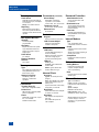
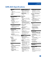
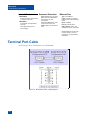
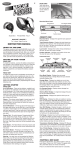
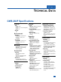
APPENDIX A
TECHNICAL DATA
CWR-264P Specifications
Physical
Size
Length: 19.0"
Height: 7.8" (10.5" of rack space)
Depth: 3.2"
Weight
4lb.
Environmental
Storage
Temperature: -50ºC to 85ºC
Humidity: 0 to 95%, noncondensing
Operating
Temperature: -40ºC to 72ºC
Humidity: 0 to 95%, noncondensing
Mounting
Standard: mounts in 19" rack
Optional: 23" rack mounting
brackets available
Construction
Chassis
Fully enclosed, anodized
aluminum
Externally accessible keypad,
LEDs and connectors
Electrical
All components mounted on
conformal coated, internal PCBs
Power
Voltage
Range: 10 to 36Vdc
Consumption
Typical: 6W
Maximum: 7W
Isolation
Power
Minimum: 3800Vdc from B and
N terminals to chassis
Internal Modem
Designed to meet FCC part 68
standards
Ethernet Port
Minimum: 3800Vdc to any
terminal
Capacities
CWR-264S
1 to 16 Secondary Units
Programmable Inputs
Virtual: 32, user assigned
Timer: 999, user assigned
Outputs
Relays: 4, dual form C, rated for
2A at 24Vdc or 1A at 125Vac,
maximum switching capacity of
125VA or 60W, service life
1 million electrical (typical)
Event Storage
Standard: 1,816,045 records
Memory Full: 129th day overwrites first day, newest data overwrites oldest data
Ethernet Port
Quantity: 1
Type: 10/100 Base-T
RS-232 Port
Quantity: 2, for use with a PC
Emulation: ANSI
Baud Rates: 300, 600, 1200,
2400, 4800, 9600, 19,200,
38,400, 57,600, 115,200
Bit Format: N-8-1
Printer Port
Quantity: 1, parallel, for use with
inkjet and laserjet printers
Capacities (continued)
Liquid Crystal Display
Characters: 80 total on 4 lines
Character Set: A-Z upper- and
lower-case, 0-9, various symbols
Viewing Area: 2.8" by .8"
Front Panel Keypad
Quantity: 20 keys
Keys: 0-9, Browse, Alpha, Setup,
Esc, Enter, Print, left, right, up/.,
down/-
Virtual Inputs
Quantity
32, user assigned
Definitions
Any logical association shared by
1 to 4 variables (i.e., Digital,
Analog, Timer or Virtual Inputs)
Assigned by defining the state of
the Virtual Input for each combination of variable states
Reporting
Creates standard Event Record
Relays can be controlled by each
Virtual Input
Modem can be set up to dial-out
Event Record
Timer Inputs
Quantity
999, user assigned
Programming
Any Digital, Analog, Virtual or
Timer Input can be assigned as
the trigger source
Any Digital, Analog or Virtual
Input can be assigned as the
terminating source
On or Off events can be assigned
as the trigger or terminating
source
113
MICRO-AIDE
CWR-264XC USER MANUAL
Timer Inputs (continued)
Limit Values
Separate high and low limits per
assigned Timer Input, in multiples
of .1 seconds
Range: 0.0 to 999.9 seconds
Reporting
Measured Time is reported in
each Timer Input Event Record
Violation of Limit Values are also
reported
Train Speed Monitor
Quantity
16 total, separately
programmable
Operation
Reports excessive train speed
Logs standard Event Record
Sensors are wired to 2 spare
Digital Inputs
Limit Values
5 to 180mph
Distance between
Sensors
50' to 5280'
Memory
Type
Non-volatile, Event Records and
Setup Database are stored in
flash memory chips
Storage Longevity
Infinite with power off
Rated for 1 million write
operations
Connectors
Terminal Ports (2)
DE-9 male, configured as DCE
Printer Port
DB-25 female, standard parallel
printer configuration
Power
Detachable, screw-down, 4-position, 12 to 22AWG
Dual B and N terminals
114
Connectors (continued)
Alarm Relays
Detachable, screw-down,
12-position, 12 to 22AWG
4 sets of N.O., N.C. and common
Telephone Line (2)
RJ-11 female, wired in parallel
Ethernet Port
RJ-45 female
Controls
Keypad
20 keys, located on front panel
LCD Contrast Adjust
Single-turn potentiometer,
located on front panel
Indicators
LCD Panel
Includes LED back lighting for
enhanced visibility
Displays numerous command
menus for configuring the
recorder and retrieving data
LEDs (3)
Power: green
Terminal: green, flashes with
send/rcv data
Modem: green, flashes with
send/rcv data and ring-in
Internal Clock
Accuracy
Typical: ±1 minute per month
(20ppm)
Sync: spare Digital Input used to
synchronize real-time clock of
Primary Unit
Synchronizes clock of Secondary
Unit(s) every 10 seconds
Resolution
Event Records are time stamped
to nearest .01 seconds
Operation
Full calendar, auto-adjusted for
leap year
Non-volatile with power off
Y2K compliant
Password Protection
Administrative Level
Access to all functions, limit
8 characters
Restricted Level
Access to Event Record and
Setup Database viewing only,
limit 8 characters
Passcode
Protects against alterations to
Setup Database via front panel,
limit 8 digits
Internal Modem
Type
V.34, 33,600 Baud, data
compression and error correction
Usage
Remote access via auto-answer
operation
Allows dial-out alarm reporting of
Virtual Input records
Compliance
Designed to meet FCC part 68
standards
Dial-out Alarms
Calling Method
Primary and secondary dial
numbers, multiple attempts
Tone or pulse dialing
Data
Issues Event Record for enabled
Virtual Inputs
Ethernet Port
Type: 10/100 Base-T
Usage: normally connected to
LAN via CAT-5 cable to Ethernet
Switch
Speed: 100Mbps
Protocol: TCP/IP, Telnet
LED Indicators: Green - link
established; Yellow - data activity
MICRO-AIDE reserves the right
to make changes, at its sole
discretion, to any specifications
listed herein.
APPENDIX A
TECHNICAL DATA
CWR-264S Specifications
Physical
Size
Isolation (continued)
Input to Adjacent Input
Analog Input Accuracy
Typical Vdc: ±1% full scale
Length: 19.0"
Digital: minimum 3800Vdc
Typical Vac: ±1.5% full scale
Height: 7.8" (10.5" of rack space)
Analog: minimum 3200Vdc
Typical Current: ±2% full scale
Depth: 3.8"
Weight
7lb.
Environmental
Storage
Ethernet Port
Minimum: 3800Vdc to any
terminal
Capacities
Inputs
Temperature: -50ºC to 85ºC
Digital: 256, all opto-isolated
Humidity: 0 to 95%, noncondensing
Analog: 8 total, 4 can measure
current
Operating
Temperature: -40ºC to 72ºC
Humidity: 0 to 95%, noncondensing
Mounting
Event Storage
Standard: 100,000 Event Record
buffer used to save records
before polling by Primary Unit
Type: non-volatile flash memory
Ethernet Port
Standard: mounts in 19" rack
Quantity: 1
Optional: 23" rack mounting
brackets available
RS-232 Port
Construction
Chassis
Fully enclosed, anodized
aluminum
Externally accessible LED and
connectors
Electrical
All components mounted on
conformal coated, internal PCBs
Power
Voltage
Range: 10 to 36Vdc
Consumption
Type: 10/100 Base-T
Quantity: 1, for use with a PC
Usage: serves as a diagnostic
port
Emulation: ANSI
Baud Rates: 300, 600, 1200,
2400, 4800, 9600, 19,200,
38,400, 57,600, 115,200
Bit Format: N-8-1
Inputs
Input Impedance
Digital: minimum 10KOhms,
opto-isolated
Analog: minimum 10MOhms
Range
Typical: 6W
Digital Input - On: 5 to 40Vdc
Maximum: 7W
Digital Input - Off: 0 to 2Vdc
Isolation
Power
Minimum: 3800Vdc from B and
N terminals to chassis and inputs
Digital Inputs
Minimum: 3800Vdc to any
terminal
Analog Inputs
Minimum: 3800Vdc to any
terminal
Analog DC Voltage: 3 scales,
±25.5, +51.1, ±255
Analog AC Voltage: 2 scales,
25.5, 255
Analog Current: 2 scales
(optional), ±25.5Adc, 25.5Aac
Event Validation Times
Digital: .01 to 327.67 seconds,
compatible with fixed rate
flashing circuits
Analog: fast and slow filter
settings
Analog Limit Values
Voltage
Separate high and low limits, in
multiples of .1V or 1V
Current
Separate high and low limits, in
multiples of .1A
Internal Temperature
Separate high and low limits,
-67ºF to 257ºF
Memory
Type
Non-volatile, Event Records and
Setup Database are stored in
flash memory chips
Storage Longevity
Infinite with power off
Rated for 1 million write
operations
Connectors
Digital and Analog Inputs
Detachable, screw-down, 6 or
8 terminals each, 12 to 22AWG
Terminal Port
DE-9 male, configured as DCE
Power
Detachable, screw-down, 4-position, 12 to 22AWG
Dual B and N terminals
Ethernet Port
RJ-45 female
Current Sensor
DE-9 female, used with CWR-CS
Indicators
LED: power, green
Internal Clock
Accuracy
Typical: ±1 minute per month
(20ppm)
Sync: Primary Unit synchronizes
each Secondary Unit cloc every
10 seconds
115
MICRO-AIDE
CWR-264XC USER MANUAL
Internal Clock (continued) Password Protection
Resolution
Event Records are time stamped
to nearest .01 seconds
Operation
Full calendar, auto-adjusted for
leap year
Non-volatile with power off
Ethernet Port
Type: Restricted only, access to
Event Record and Setup Database viewing only, limit
8 characters
Type: 10/100 Base-T
Entire Setup Database is under
control of the Primary Unit
Speed: 100Mbps
Usage: applies only to Terminal
Port
Y2K compliant
Usage: normally connected to
LAN via CAT-5 cable to Ethernet
Switch
Protocol: TCP/IP, Telnet
LED Indicators: Green - link
established; Yellow - data activity
MICRO-AIDE reserves the right
to make changes, at its sole
discretion, to any specifications
listed herein.
Terminal Port Cable
The following cable is included with every CWR-264XC.
Figure 13 - Terminal Port Cable - Wiring Diagram
116