1
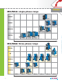
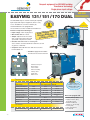
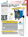
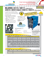
Introduction
pages 3-2 & 3-3
WELDING POWER SOURCES
Transformer technology power sources
EASYMIG 131 / 151 / 170 DUAL
page 3-6
MAXISTAR 180 M / 200 M / 250 T / 280 T
page 3-7
BLUMIG 241 C / 281 C / 243 C / 253 C / 283 C / 353 C
page 3-8
BLUMIG 303 S / 353 S / 403 S / 503 S
page 3-9
TF 300 / 400 / 400 H (wire feeders for BLUMIG S)
MIG/MAG
WELDING EQUIPMENT
CHAPTER 3
MIG/MAG welding
page 3-10
Inverter technology power sources
PRECISA 201 SG
page 3-11
PRECISA 420 PH
pages 3-12 & 3-13
Thyristor technology power source
MT 603 S(H)
pages 3-14 & 3-15
Options and accessories
Rollers for wire feeders, pressure regulators / flowmeters etc...
page 3-16
TORCHES
MIG/MAG torches
page 3-17
Wear parts for MIG/MAG torches
page 3-18
For all accessories
and protection products,
consult our WELDLINE
catalogue and visit
our website
www.weldline-alw.com.
3-1
MIG/MAG Welding Process
A TYPICAL MANUAL MIG/MAG WELDING INSTALLATION
mask
pressure regulator/ flowmeter
protective
clothing
fume extraction
work
piece
earth clamp
gas
power source
with wire feeder
torch harness
earth cable
METAL TRANSFER MODE
Torch
Nozzle
Contact tip
Gaseous protection
Molten weld pool
Electrode wire
Weld bead
MIG/MAG Welding Process
The MIG/MAG welding processes use
an arc under gaseous protection.
The electrode is a metallic wire.
The electrode, the metal transferred in the arc
and the weld bead are protected from the
atmosphere by an inert gas for MIG welding
and an active gas for MAG welding.
The definition explains the names MIG
(Metal Inert Gas) and MAG (Metal Active Gas).
In manual welding this process is called
semi-automatic because the wire is fed
automatically as soon as the arc starts.
3-2
LEXICON
mild steel
stainless steel
aluminium
and copper alloys
MIG/MAG process (semi-auto)
Gas recommendation:
ARCAL 21
ARCAL 14
ATAL 5
ARCAL 12
ARCAL 121
NOXALIC 12
ARCAL 1
ARCAL 31
ARCAL 32 or 37
SELF positions:
SELF role:
- used in short-circuit mode,
- limits the short-circuit current,
- the higher the SELF, the colder,
the weld bead.
Ω Small SELF
Used for thinner sections
ΩΩ Big SELF
Used for thinner sections
• ARC is very smooth
• Lower welding speed
ΩΩΩ Total SELF
Used for thinner sections
• ARC is rigid
• Higher welding speed
SEMIAUTOMATIC
WELDING
MIG (Metal Inert Gas):
Arc welding process with a
consumable wire. This wire is
transferred in the arc and the
molten metal is deposited in
the molten pool, protected by
an inert gas.
MAG (Metal Active Gas):
Same description as MIG
but the gas protection
is active (CO2 or
argon + CO2 mixture).
MIG/MAG
WELDING EQUIPMENT
Gas selection:
MIG pulse:
The current varies during
welding, the power supplies
a very precise “shape wave”.
Pulse is primarily used
for stainless steel and
light alloys.
Synergic MIG:
The welding parameters are
programmed in the power
source set for a common
evolution according to a
predefined law. One single
setting is needed which
facilitates the use of those
machines and improves the
welding quality.
2 Times mode:
Welding starts by pulling the
torch’s trigger. It stops
by releasing the trigger.
Spot mode:
The power source starts
to weld when the trigger
is pulled, but welding
stops automatically after a
pre-set delay.
Intermittent mode:
This is a point mode which
is repeatable. If the pressure
on the trigger is maintained,
welding will be re-started
after another delay which
is also regulated.
3-3
MIG/MAG
MIG/MAG: single-phase range
PRECISA
201 SG
BLUMIG
241 C
281 C
MAXISTAR
180 M / 180 MEC
200 M
EASYMIG
105 A
131 DUAL
151 DUAL
170 DUAL
115 A
140 A
170 A
220 A
240 A
280 A
MIG/MAG: three-phase range
PRECISA
420 PH
MT
603 SH
BLUMIG S
303 S
353 S
283 C /
253 ALU
353 C
403 S
503 S/SH
BLUMIG C
243 C
MAXISTAR
250 T
220 A
3-4
260 A
280 T
280 A
330 A
400 A
500 A
520 A
THE CLASS LEADER
INNOVATION
QUALITY
AT THE
RIGHT PRICE
SAFETY
3-5
MIG/MAG
WELDING EQUIPMENT
PRECISA 420 PH
MIG / MAG WELDING EQUIPMENT
MIG/MAG
POWER SOURCES
Compact equipment for MIG/MAG welding.
Transformer technology.
Single-phase input voltage.
EASYMIG 131/151/170 DUAL
MIG/MAG
POWER SOURCES
The EASYMIG range is used for smaller jobs requiring
light weight and compact equipment, which is easy
to use. Available for use: with or without gas,
the EASYMIG units are equipped with
the essential accessories needed for immediate use.
EN 60974-1
EN 60974-10
LE FOR
B
A
T
R
PO
E
ENANC
MAINT
TIONS
OPERA
Input voltage: 230 V single-phase.
Wire feeder device: 2 rollers.
Simple: adjustment of the current
with a switch and of the wire feed
speed with a single knot control.
Versatile: EASYMIG DUAL for welding with
steel, stainless steel and aluminium solid wires as well
as gasless cored wires.
Complete: delivered with torch and all accessories
for immediate use.
2006-435
Features and product advantages:
Standards
Portable: equipped with handle
and wheels for easier movement.
1
3
7
1 Handle for transport.
2 On/off switch.
4
2006-438
2
5
2006-433
3 Power switch.
4 Wire feed setting.
6
TECHNICAL
5 Primary cable.
6 Earth cable.
7 Built-in torch.
CHARACTERISTICS:
EASYMIG 131 DUAL EASYMIG 151 DUAL
Input voltage
Primary consumption
Effective input current
Welding voltage
Welding current range
Duty cycle at 40 °C
20 A
• Wear parts for
torches see page 3-19
• Wire-feeder roller
see page 3-16
24 A
7.7 A
8.5 A
10.2 A
20 - 36 V
18 - 32 V
30 - 105 A
30 - 115 A
30 - 140 A
105 A (15%)
115 A (15%)
140 A (18%)
4
Protection index
Weight
22 A
20 - 35 V
Adjustment positions
Dimensions
EASYMIG 170 DUAL
230 V - single-phase (50/60 Hz)
6
IP 21
Delivered equipped with:
240 x 510 x 370 mm
240 x 510 x 460 mm
440 x 670 x 750 mm
21 kg
23.5 kg
36 kg
TO
ORDER:
Power source only
3-6
W 000 263 720
W 000 263 721
W 000 263 722
electric primary cable,
equipped earth cable,
and built-in torch,
handle and wheels
(wheels on 151 & 170),
2 roller plate,
safety instructions,
user manual.
Compact equipment for MIG/MAG welding.
Transformer technology.
Single-phase (M) or three-phase (T) input voltage.
R
INES FO
H
C
A
M
CT
ATIONS
COMPA
C
I
L
P
P
LIGHT A
Standards
EN 60974-1
EN 60974-10
Features and product advantages:
Input voltage: 230 V single-phase or 400 V three-phase.
Mode: continuous or tack welding.
Wire feeder: 2 roller plate.
Simple: adjustment of the current with a switch
and of the wire feed speed with a single knob control.
Versatile: for welding with steel,
stainless steel and aluminium wires.
Reliable: air cooled transformer.
2007-228
4
1
5
2
6
3 Power switch.
4 Tack welding adjustment.
7
5 Stick-out adjustment.
6 Starting speed regulation.
2007-227
3
1 Thermal safety indicator.
2 Switch on/off.
8
TECHNICAL
7 Wire feed speed.
8 European connection for torch.
CHARACTERISTICS:
MAXISTAR
180 MEC
Input voltage 50 Hz
MAXISTAR
200 M
MAXISTAR
250 T
230 V - single-phase
MAXISTAR
280 T
400 V - three-phase
Primary consumption
24 A
32 A
11 A
10 A
Effective consumption
7.5 A
12 A
5.5 A
5.5 A
6
8
6
7
Welding voltage
18 - 32 V
18 - 33 V
18 - 35 V
17 - 35 V
Welding current
30 - 170 A
35 - 180 A
35 - 200 A
35 - 200 A
Wire diameter
0.6 - 0.8 mm
0.6 - 0.8 mm
0.6 - 1.0 mm
0.6 - 1.0 mm
Duty cycle
at 40 °C
at 30%
140 A (18%)
180 A (15%)
200 A (25%)
200 A
at 60%
75 A
100 A
130 A
140 A
at 100%
60 A
75 A
100 A
110 A
Adjustment positions
Protection index
IP 21
Dimensions (mm)
Weight
IP 23
440 x 670 x 750
38.5 kg
• Torches see pages 3-17/18
• Rollers see page 3-17
43 kg
500 x 870 x 950
54 kg
71 kg
Delivered equipped with:
TO
ORDER:
Power source only
W 000 263 724 W 000 263 725
W 000 263 726
Options
Reverse polarity kit
W 000 263 727
W 000 257 998
electric primary cable,
equipped earth cable,
2 roller plate for wire sizes
0.6 - 0.8 mm, 1.0 - 1.2 mm,
safety instructions,
user manual,
torch (only for
MAXISTAR 180 M).
3-7
MIG/MAG
WELDING EQUIPMENT
MAXISTAR is a range of semi-automatic MIG/MAG
welding equipment. Used for welding applications
in workshops or for outdoor work.
MIG / MAG WELDING EQUIPMENT
MAXISTAR 180 MEC / 200 M
MAXISTAR 250 T / 280 T
MIG/MAG
POWER SOURCES
Compact equipment for MIG/MAG welding.
Transformer technology.
Single-phase or three-phase input voltage.
MIG/MAG
POWER SOURCES
BLUMIG 241 C / 281 C - (single-phase)
243 C / 253 C ALU / 283 C / 353 C - (three-phase)
The BLUMIG range of MIG/MAG welding
equipment is robust and powerful, providing
the best performance on the market and will
meet all your needs.
S
ACHINE
M
T
C
A
E
COMP
IVE US
S
N
E
T
N
FOR I
Standards
EN 60974-1
EN 60974-10
Features and product advantages:
Input voltage: 230 V single-phase
and 230 - 400 V three-phase.
Mode: 2 T / 4T / tack welding.
Digital display: included
on the BLUMIG 353 and
an option for other models.
Wire feeder: 4 roller plate.
Versatile: range of gases.
Simple: adjustment of the current
with a switch and of the wire feed
speed with a single knob control.
Reliable: air cooled
transformer.
2007-154
1
2
4
6
• Torches see pages 3-17/18
• Rollers see page 3-17
3
5
1 Selection 2T / 4T / tack welding.
2 Tack welding adjustment.
7
8
9
2007-153
3 Displays.
4 Stick-out adjustment.
Delivered equipped with:
7 Power switch.
8 Switch on/off.
5 Wire speed.
6 Starting speed adjustment. 9 European connection for torch.
TECHNICAL
CHARACTERISTICS:
electric primary cable,
equipped earth cable,
rollers 0.8- 1.0 mm,
safety instructions,
user manual.
BLUMIG 241 C BLUMIG 281 C BLUMIG 243 C BLUMIG 283 C BLUMIG 353 C BLUMIG 253 ALU
Input voltage
230 V single-phase
230 - 400 V three-phase
Primary consumption
38 A
54 A
19 -11 A
27 - 15 A
33 - 19 A
27 - 15 A
Effective consumption
19 A
30 A
10 - 6 A
15 - 9 A
20 - 11 A
15 - 9 A
Adjustment positions
10
14
7
10
14
10
18 - 35 V
20 - 53 V
18 - 35 V
18 - 40 V
18 - 45 V
18 - 40 V
Welding current range
40 A - 240 A
32 A - 280 A
35 A - 220 A
35 A - 280 A
35 A - 350 A
35 A - 280 A
Wire diameter
0.6 - 1.0 mm
0.6 - 1.0 mm
0.6 - 1.0 mm
0.6 - 1.0 mm
0.6 - 1.2 mm
0.6 - 1.0 mm
at 30%
Duty cycle
at 60%
at 40 °C
at 100%
200 A (25%)
250 A
200 A
250 A
350 A
250 A
130 A
175 A
140 A
170 A
270 A
170 A
100 A
140 A
110 A
140 A
210 A
140 A
Welding voltage
Protection index
IP 23
Dimensions (mm)
Weight
TO
500 x 870 x 950
570 x 930 x 990 500 x 870 x 950
71 kg
86 kg
71 kg
80 kg
96 kg
80 kg
W 000 261 955
W 000 261 962
W 000 263 728
W 000 262 179
W 000 263 729
W 000 264 208
ORDER:
Power source only
Options
3-8
Reverse polarity kit
W 000 257 998
Digital display
W 000 352 093
Equipment with separate wire feeders
for MIG/MAG welding. Transformer technology.
Three-phase input voltage.
FEEDER
E
R
I
W
TE
SEPARA VY DUTY
HEA
The BLUMIG range of MIG/MAG welding equipment is
robust and powerful, providing the best performance
on the market and will meet all your needs.
5
6
7
8
1
2
3
4
5
6
2007-156
6
9
TECHNICAL
Stick-out: adjustable with a potentiometer.
Simple: adjustment of the current
with a switch and of the wire feed
speed with a single knot control.
Digital display: precise adjustment and
optimal reading (standard with 353/403).
Versatile: for all solid or flux cored wires.
Powerful: air cooled transformer.
Safety: protection class IP 23.
Ergonomic design: due to its pivoting
wire feed unit support.
Selection 2T / 4T / tack welding.
Tack welding adjustment.
Wire speed.
7 European connection for torch
Stick-out adjustment.
8 Power and on/off switch.
Starting speed regulation.
9 Power switch (precise adjustment).
Digital displays.
CHARACTERISTICS:
BLUMIG 303 S
Compatible wire feeders
BLUMIG 353 S
BLUMIG 403 S
TF 300 - TF 400
Input voltage 50 Hz
BLUMIG 503 S / SH
TF 400 - TF 400H
230 V - 400 V three-phase
Primary consumption
27 - 15 A
33 - 19 A
42 - 24 A
60 - 34 A
Effective consumption
15 - 8.5 A
20 - 11 A
25 - 14 A
35 - 20 A
10
14
21
30
Adjustment positions
Welding voltage
18 - 40 V
18 - 45 V
18 - 46 V
19 - 54 V
Welding current
35 - 280 A
40 - 330 A
35 - 400 A
50 - 500 A
Wire diameter
0.8 - 1.0 mm
0.8 - 1.2 mm
0.8 - 1.2 mm
0.8 - 1.6 mm
Duty cycle
at 40 °C
at 35%
250 A (30%)
300 A
350 A
450 A
at 60%
170 A
230 A
270 A
345 A
at 100%
140 A
180 A
210 A
270 A
Protection index
• Wire feeder
see page 3-11
• Torches
see pages 3-17/18
• Rollers
see page 3-17
IP 23
Dimensions (mm)
500 x 1180 x 950
Weight
TO
EN 60974-1
EN 60974-10
2007-157
Features and product advantages:
Input voltage: 230 V - 400 V
three-phase.
Mode: 2 T / 4T / tack welding.
Wire feeder: 4 roller plate.
Perfect starting:
possibility to
1
adjust the
2
3
starting speed.
4
Standards
73 kg
84 kg
600 x 1250 x 1050
104 kg
145 kg
W 000 263 732
W 000 263 734 (S)
W 000 263 735 (SH)
ORDER:
Power source only
W 000 263 730 W 000 263 731
Cooler unit
-
-
-
W 000 262 188*
Delivered equipped with:
Liquid for cooling
unit
-
-
-
W 000 227 236*
Options
Digital display
W 000 352 093
* For BLUMIG 503 SH only
of series
electric primary cable,
equipped earth cable,
safety instructions,
user manual.
3-9
MIG/MAG
WELDING EQUIPMENT
BLUMIG 303 S / 353 S
BLUMIG 403 S / 503 SH
MIG / MAG WELDING EQUIPMENT
MIG/MAG
POWER SOURCES
Wire feeder with cables
for BLUMIG S power sources.
MIG/MAG
WIRE FEEDER
TF 300 (air) / 400 (air)
/ 400H (water)
2006-896
The TF wire feeders are compatible with all the power sources
in the BLUMIG S range.
Delivered as standard with an insulated cable.
Features and product advantages:
Sealed structure: protection of the wire feeding system.
Digital display: A/V included on TF 400 and TF 400H.
Ergonomic design: adjustment on the front panel,
and pivoting wire feed unit support for easier storage
and orientation of the wire feeders.
Efficient wire feeding: 4 roller plate.
Safety: secure locking of the wire feeding compartment.
3
4
5
6
2
2007-032
1 Digital display A/V.
2 Wire speed.
7
1
8
9
3 Mode 2T / 4T / tack welding.
4 Tack welding adjustment.
5 Starting speed.
6 Stick-out adjustment.
Rollers see page 3-17
7 Test / Purge gas / Wire advance.
8 Torch connection.
9 Water inlet / outlet on TF 400H type.
TECHNICAL DATA:
TF 300 - TF 400 - TF 400 H
TF 300 AIR
TF 400 AIR
Digital display A/V
-
Wheels
Equipped for water cooled torch
-
-
Rollers
Cat. no.
3-10
TF 400 WATER
0.8 - 1.0 mm / 1.0 - 1.2 mm for steel
TF 300
TF 400
TF 400 H
Cable length 5 m
W 000 263 745
W 000 263 747
W 000 263 749
Cable length 10 m
W 000 263 746
W 000 263 781
W 000 263 750
Cable length 20 m
-
W 000 263 748
W 000 263 751
Multi-process MIG/MAG welding power source.
Portable with inverter technology.
Single-phase input voltage.
The MX 201 SG / PRECISA 201 SG is a multi-process
inverter technology power source. Its weight, power and
primary single-phase input voltage, make the PRECISA 201
the specialist for rapid maintenance operations.
BLE
P O RTA
OCESS
R
P
I
T
L
MU
4
1
5
1 Digital display.
2 Program mode buttons.
9
3 Potentiometer.
4 MIG / MMA / TIG DC selection.
2
8
5 Selection 2T / 4T / point.
6 European connector for torch.
6
7
3
EN 60974-1
EN 60974-10
2007-630
Features and product advantages:
Input voltage: 230 V single-phase.
Display: digital A / V.
Multi-process: MIG / MMA / TIG DC.
Wire feeder: 2 roller.
Professional: robust construction with handle.
Programmable: 9 programs available, 11 program memory.
Polarity inversion: for welding applications with gasless flux cored wire.
Wire spool: D 200, D 300 optimal.
MIG torch connections: with European connectors or Spool Gun.
Standards
2007-629
7 Spool Gun connection control.
8 Welding current adjustment.
9 Wire speed regulation.
TECHNICAL
CHARACTERISTICS:
MMA
Input voltage 50/60 Hz
PRECISA 201 SG
TIG
MIG
230 V single-phase
Primary consumption
23 A
16 A
21 A
Effective consumption
35 A
27 A
35 A
Open circuit voltage
Welding current range
25 V
50 A
5 A - 200 A
30 - 200 A
200 A
at 35%
-
200 A
at 40%
180 A
-
-
at 60%
140 A
155 A
155 A
at 100%
115 A
125 A
125 A
Duty cycle
at 40 °C
Wire diameter
Protection index
Dimensions
Weight
TO
70 A
28 - 180 A
• Torches see pages 3-17/18
• Rollers see page 3-17
0.6 - 1.0 mm
IP 23
235 x 470 x 570 mm
29 kg
ORDER:
Delivered equipped with:
Power source only
W 000 263 772
Options
15 kg spool support
W 000 253 322
electric primary cable,
earth cable,
rollers for wires 0.8 / 1.0 mm,
safety instructions,
user manual.
3-11
MIG/MAG
WELDING EQUIPMENT
PRECISA 201 SG
MIG / MAG WELDING EQUIPMENT
MIG/MAG
POWER SOURCES
MIG/MAG welding power source.
Inverter pulsed technology.
Three-phase input voltage.
MIG/MAG
POWER SOURCES
PRECISA 420 PH
The PRECISA 420 PH is the ideal partner when it comes to the
flexibility required for welding on all materials (steel, light alloys or
applications such as agricultural machines, metallic furniture, etc...).
Designed for both conventional and advanced MIG/MAG
processes (for thin plate MIG brazing etc...) and also for MMA
applications. This machine is optimized due to the facilities
for adjustment and the wide range of synergic programs
for all materials and gas combinations. This installation
is the best solution for an efficient machine, which is easy
to adjust and easy to use.
Standards
EN 60974-1
EN 60974-10
Features and product advantages:
Numerical control of parameters giving exceptional
arc stability and welding quality.
Water cooled.
Easy selection of parameters,
easy to read digital displays.
Synergic curves available as standard to optimize
results with a simple “one button” selection.
A wide set of welding processes available
for optimum welding in all situations:
- Speed Short ArcTM: high welding speed / low
deformation on thin plates,
- Pulsed: for optimum aluminium and stainless
steel welding,
- Cold Double PulseTM: for the highest quality
on thin plates especially stainless and aluminium,
weld bead with TIG aspect,
- MIG Brazing: for thin coated plates, e.g. car body repair,
with low deformation and good mechanical
characteristics.
1
2
R
SED FO
L
U
P
C
S
GI
SYNER
R E S U LT
G
N
I
D
EL
TOP W
1 Welding voltage and set up parameter display.
10
3
8
2008-777
2 Welding current or wire speed or thickness display.
3 Mode and welding cycle selection LEDs.
9
4 Process choice selector.
4
7
5 Gas selector.
6 Wire grade selector.
5
7 Wire diameter selector.
6
2008-775
8 Scrolling of set up parameters.
3-12
9 Parameter setting.
10 Selector for wire speed or thickness display.
• Torches see pages 3-17/18
• Rollers see page 3-17
MIG/MAG welding power source.
Inverter pulsed technology.
Three-phase input voltage.
Spray end
Synergic mode
Semi-synergic mode
Parameter saving
Display calibration
Assisted calibration
Software update
Error messages
Language choice
2008-774
A
B
TECHNICAL
2005-691
Basic functions:
Wire speed setting (empty)
Wire speed setting (welding)
Arc length setting (empty)
Arc length setting (welding)
End setting (empty)
End setting (welding)
Spot 2T/4T/cycle
Hot start
Fading
CHARACTERISTICS:
PRECISA 420 PH
400 V - 50/60 Hz
44.5 A (60%) - 39 A (100%)
106 V
20 A - 420 A
420 A
350 A
IP 23 S
1150 x 750 x 1500 mm
107 kg
at 45%
Duty cycle
at 40 °C
at 100%
Protection index
Dimensions (with trolley and feeder)
Weight
A
B
C
D
ORDER:
Power source water cooled
Option
Wire feeder TF 420H
Workshop trolley for power source
Pivot stand (requires wire feeder trolley)
Workshop trolley for wire feeder
RC-JOB remote control
Harnesses
2m
5m
10 m
15 m
W 000 273 132
W
W
W
W
W 000 273 133
W 000 550 046
W 000 550 048
W 000 550 050
W 000 273 134
Steel
Aluminium
000 055 091 W 000 055 095
000 055 092
000 055 093 W 000 055 096
000 055 094 W 000 055 097
D
2008-778
TO
C
2005-690
Three-phase input voltage
Primary consumption
Open circuit voltage
Welding current range
Delivered equipped with:
electric primary cable, safety instructions,
earth cable,
user manual.
rollers for wire 0.8 / 1.0 mm,
3-13
MIG/MAG
WELDING EQUIPMENT
PRECISA 420 PH
MIG / MAG WELDING EQUIPMENT
MIG/MAG
POWER SOURCES
Separate wire feeder installation
for MIG/MAG welding. Thyristors technology.
Three-phase input voltage.
MIG/MAG
POWER SOURCES
MT 603 SH
The MT 603 S(H) is a synergic thyristor controlled unit for MIG-MAG welding.
Robust and powerful it has been designed to produce high quality welds for
the widest range of industrial applications.
The separate wire feeders (air-water cooled) are available with different lengths
of harness for all your welding needs.
Standards
EN 60974-1
EN 60974-10
Input voltage: 220-230-240-380-400-415-440 V three-phase.
Mode: 2T / 4T welding cycle.
Wire feeder: 4 roller plate.
Perfect starting: possibility to adjust the starting speed.
Arc extinction device (stick-out): adjustable with knob.
Simple: easy adjustment of the welding parameters with the OPT system
function which is a synergic mode with access to pre recorded parameters
which optimise welding performance.
Flexibility: possibility to modify the welding parameters (also in welding)
from the wire feeder or from the remote control when available.
Digital display: precise pre-setting of welding thickness or wire speed
and optimal reading of welding parameters (A + V).
Versatile: for all solid or flux cored wire welding.
Powerful: power transformer, choke and rectifier air cooled.
Safety: protection class IP 23.
Ergonomic: due to its
pivoting wire feed unit
support (option).
2008-553
Features and product advantages:
OL
CONTR GY
C
I
G
R
E
LO
SYN
ECHNO
T
R
O
T
THYRIS
3
5
7
1
TECHNICAL
10
CHARACTERISTICS:
9
2
MT 603 SH
Wire feeder range
220-230-240-380-400
415-440 V
Primary consumption at I max.
77.6 A (230 V) - 44.6 A (400 V)
Effective consumption
60.1 A (230 V) - 34.5 (400 V)
Voltage regulation
Continuous adjustement
Open-circuit voltage
40 - 520 A
Wire diameter
Dimensions
Weight
1 2T / 4T welding
2
3
4
61 V
Welding current
Protection index
5
0.8 - 1.6 mm (2.4 mm FCW)
at 60%
520 A
at 100%
370 A
IP 23
680 x 460 x 1200 mm
208 kg
ORDER:
Power source only
3-14
W 000 263 736
cycle.
Crater filler cycle.
Gas selection.
Solid or cored
wire selection.
Display for current,
thickness and
wire speed.
6 Voltage display.
7 Selection for
the display 5.
8 Material selection.
9 Wire diameter
10
11
selection.
ON and warning
lamps.
ON / OFF switch.
Delivered equipped with:
TO
6
DV44i - DV44iw
Three-phase input
voltage (50 / 60 Hz)
Duty cycle at 40 °C
4
11
8
primary cable 5 m,
earth cable 5 m with clamp,
gas hose 2 m,
safety instructions,
user manual.
Separate wire feeder installation
for MIG/MAG welding. Thyristor technology.
Three-phase input voltage.
MIG/MAG
POWER SOURCES
MT 603 SH Additional units
DV44i
• For torches
see page 3-18/19
W 000 302 009
W 000 010 167
(air)
/ DV44iw
The DV44i(w) wire feeders are compatible with the MT 603 S(W)
power source. They are delivered as standard with sheathed
cables (different lengths), trolley and spool cover.
Wire feeder for intensive use.
(water)
ERS
4 ROLL
m
R 37 m
E
T
E
M
DIA
EN 60974-5
2001-375
Features and product advantages:
Sealed structure: protection of the wire feeding system.
Easy to use: synergic and manual adjustment of welding parameters.
Comfortable: due to its pivoting wire feed unit support (option)
changing the orientation of the feeder making welding easier.
Efficient wire feeding: 4 roller plate.
Safety: no access to moving parts and protection enclosure IP 23.
Simple: feeder with handle for ease of movement.
Robust: sheathed cables and torch support.
Versatile: for all kinds of solid and flux
cored wires up to 2.4 mm.
Standards
Rollers see page 3-17
TO
A
ORDER:
Wire feeder
DV 44i D37 (air)
5m
W 000 268 844
10 m
W 000 268 845
15 m
W 000 268 846
Wire feeder
DV 44iW D37 (water)
5m
W 000 268 847
10 m
W 000 268 848
15 m
W 000 268 849
Torch WMT 36 A - 3 m (air)
W 000 010 605
Torch WMT 500 W - 3 m (water)
W 000 010 608
C
Options
A
B
C
B
Remote control
W 000 305 112
Pivot support
W 000 305 010
Slinging ring
W 000 305 061
3-15
MIG/MAG
WELDING EQUIPMENT
Cooler unit
COOLER II
Liquide for cooling unit
FREEZCOOL 10L
MIG / MAG WELDING EQUIPMENT
ORDER:
2008-146
TO
Options and accessories
for MIG/MAG power sources.
MIG/MAG
OPTIONS
1. ROLLERS FOR WIRE FEEDERS
EASYMIG / MAXISTAR ranges
Roller
BLUMIG range
Steel
Roller
Steel
Alu
0.6 / 0.8 mm
W 000 232 110
0.6 mm
W 000 050 096
-
-
1.0 / 1.2 mm
W 000 232 112
0.8 mm
W 000 050 097
W 000 050 100
-
Entry wire guide W 000 231 810
1.0 mm
W 000 050 098
W 000 050 101
-
1.2 mm
W 000 050 099
W 000 050 102 W 000 264 870 (1.0 / 1.2 mm)
1.6 mm
W 000 218 767
Flux cored wire
-
W 000 265 883 (1.4 / 1.6 mm)
Entry wire guide
W 000 233 472
Intermediate wire guide
W 000 252 183
Exit wire guide
W 000 269 661
PRECISA 201 SG range
Roller
Steel
Alu
0.6 - 0.8 mm
W 000 352 037
-
-
1.0 - 1.2 mm
W 000 352 036
W 000 270 323
W 000 227 891
Entry wire guide
Flux cored wire
W 000 227 907
MT 603 S(H) range
Entry wire guide
0.6
1.0
Intermediate wire guide
W 000 305 150
1.2
W 000 267 598
ALUKIT
W 000 271 819
W 000 271 820
W 000 267 599
W 000 271 821
W 000 305 126
1.6
1.0 - 1.2
W 000 260 185
Alu
1.2 - 1.6
W 000 260 186
1.6 - 2.4
W 000 260 187
Flux
cored
wire
1.0 - 1.2
1.2 - 1.6
Exit wire guide
W 000 305 125
0.8
Steel
Roller
W 000 305 150
1.6 - 2.4
W 000 255 648
W 000 305 135
W 000 255 649
W 000 255 650
W 000 271 820
W 000 271 821
W 000 266 330
W 000 266 331
2. WELDING TORCHES
EASYMIG/MAXISTAR ranges
Replacement torch
EASYMIG 151
EASYMIG 170
MAXISTAR 180
W 000 264 746
W 000 228 236
W 000 228 238
MAXISTAR / BLUMIG / PRECISA ranges
Torches
WMT 15 A
Cooling
Duty cycle at 60%
CO2
WMT 36 A
WMT 500 W
Air
Air
Air
Water
180 A
230 A
360 A
500 A (at 100%)
Ar + CO2
150 A
200 A
330 A
450 A (at 100%)
3m
W 000 010 600
W 000 010 602
W 000 010 605
W 000 010 608
4m
W 000 010 601
W 000 010 603
W 000 010 606
W 000 010 609
5m
-
W 000 010 604
W 000 010 607
W 000 010 610
Length
3-16
WMT 25 A
Spool Gun SG 150 Aria - 150 A - 100% - 6 m
W 000 228 491
Spool Gun SG 300 Aria - 300 A - 100% - 6 m
W 000 228 490
MIG/MAG torches.
MIG/MAG
TORCHES
WMT MIG/MAG torches
A complete range of torches for
MIG/MAG welding, designed
to meet all requirements when
semi-automatic welding.
Standards
EN 60974-1
EN 60974-7
• WMT 15 A:
for car bodies due to its compactness.
• WMT 25 A:
for metal construction
and maintenance jobs.
2007-139
• WMT 36 A:
• WMT 500 W:
WEAR
for boiler making and metal
frame manufacturing.
2007-140
Features and product advantages:
Well balanced.
Ergonomic handle for a perfect grip.
Flexibility due to the back knee joint.
Wear parts according to European
standard.
European connector.
Rest hook.
for heavy duty work needing
a water cooled torch.
TECHNICAL CHARACTERISTICS:
TORCH
WMT 15 A
WMT 25 A
WMT 36 A
Cooling
air
air
air
water
CO2
180 A
230 A
360 A
500 A
Ar + CO2
150 A
200 A
330 A
450 A
Steel 0.6 to 1.0 mm
Steel 0.8 to 1.2 mm
Steel 0.8 to 1.6 mm
Steel 0.8 to 2.4 mm
Duty cycle at 60%
Voltage class
Suitable wires
WMT 500 W
L 113 - 1
-
Alum. 1.0 to 1.2 mm Alum. 1.0 to 1.6 mm Alum. 1.0 to 2.4 mm
Gas flow
10 to 18 l/min
10 to 18 l/min
10 to 18 l/min
10 to 25 l/min
Contact tip
Steel 0.8 mm
Steel 1.0 mm
Steel 1.2 mm
Steel 1.2 mm
12.5 mm
14.0 mm
16.0 mm
16.5 mm
Sheath
For steel wire
0.6 - 0.8 mm
For steel wire
1.0 - 1.2 mm
For steel wire
1.0 - 1.2 mm
For steel wire
1.0 - 1.2 mm
Length
WMT 15 A
WMT 25 A
WMT 36 A
WMT 500 W
3m
W 000 010 600
W 000 010 602
W 000 010 605
W 000 010 608
4m
W 000 010 601
W 000 010 603
W 000 010 606
W 000 010 609
5m
-
W 000 010 604
W 000 010 607
W 000 010 610
Delivered equipped with
Nozzle (diameter)
3-17
MIG/MAG
WELDING EQUIPMENT
a Profess
io
Environm nal
ent
www.we
ldline-alw
.com
PARTS FOR MIG / MAG TORCHES
Creating
Wear parts for WMT MIG/MAG torches.
MIG/MAG
TORCHES
1.
2.
3.
4.
1
Nozzle
Contact tip
Clamp
Diffuser
2
3
4
PU
2007-138
WEAR PARTS:
Types
M6 x 25 steel
M6 x 28 steel
CONTACT
M6 x 28 alu
TIP
M8 x 30 steel
M8 x 30 alu
CLAMP
DIFFUSER
0.8 AC
W 000 010 821
1.0 AC
W 000 010 822
0.8 AC
W 000 010 826
1.0 AC
W 000 010 827
1.2 AC
W 000 010 828
1.0 Al
W 000 010 850
1.2 Al
W 000 010 851
0.8 AC
W 000 010 834
1.0 AC
W 000 010 835
1.2 AC
W 000 010 836
1.6 AC
W 000 010 837
1.0 Al
W 000 010 853
1.2 Al
W 000 010 854
W 000 010 855
M6 x 35
-
W 000 010 720
M6 x 28
-
W 000 010 722
M8 x 25
-
W 000 010 724
classical
-
W 000 010 780
high temp.
-
W 000 010 781
ceramics
-
W 000 010 782
classical
-
W 000 010 783
high temp.
-
W 000 010 784
conical
NOZZLE
-
W 000 010 785
12.5 mm
W 000 010 786
10.0 mm
W 000 010 787
14.0 mm
W 000 010 790
12.0 mm
W 000 010 791
16.0 mm
W 000 010 794
14.0 mm
W 000 010 795
16.5 mm
W 000 010 797
14.5 mm
W 000 010 798
16.0 mm
W 000 010 788
17.0 mm
W 000 010 792
20.0 mm
W 000 010 796
20.0 mm
W 000 010 799
steel - length 3 m 0.6 - 0.8
W 000 010 730
steel - length 4 m 1.0 - 1.2
W 000 010 731
cylindrical
3-18
Cat. nr
W 000 010 820
1.6 Al
ceramics
SHEATH
Ø
0.6 AC
alu - length 3 m 0.6 - 0.8
W 000 010 733
alu - length 4 m 1.0 - 1.2
W 000 010 734
alu - length 3 m 1.0 - 1.2
W 000 010 736
WMT 15 A WMT 25 A WMT 36 A WMT 500 W