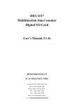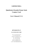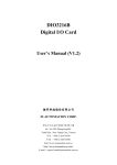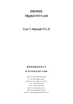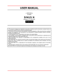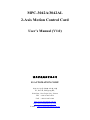
1
MPC-3042A/3042AL
2-Axis Motion Control Card
User’s Manual (V1.0)
健昇科技股份有限公司
JS AUTOMATION CORP.
新北市汐止區中興路 100 號 6 樓
6F., No.100, Zhongxing Rd.,
Xizhi Dist., New Taipei City, Taiwan
TEL:+886-2-2647-6936
FAX:+886-2-2647-6940
http://www.automation.com.tw
http://www.automation-js.com/
E-mail:[email protected]
Correction record
Version
Record
1.0
For driver 1.0 up
1
Contents
1.
2.
Forward.................................................................................................................................................. 5
Features ................................................................................................................................................. 6
2.1
Main card....................................................................................................................................... 6
2.2
Din rail mounted wiring board ...................................................................................................... 6
3. Specifications ........................................................................................................................................ 7
3.1
MPC-3042A/3042AL Main card................................................................................................... 7
3.2
Din rail mounted wiring board ...................................................................................................... 8
4. Layout and dimension ........................................................................................................................... 9
4.1
MPC-3042A/3042AL Main card................................................................................................... 9
4.2
ADP-2042DIN for JF1 Din rail mounted wiring board ................................................................ 9
4.3
JS51050 for JM4 25PM Din rail mounted dummy wiring board.................................................. 10
4.4
ADP-9201DIN for ADP9201_JM1 Din rail mounted wiring board ............................................. 10
5. Pin definitions........................................................................................................................................ 11
5.1
JF1 Assignment / Definitions ........................................................................................................ 11
5.2
JM1 Assignment / Definitions ....................................................................................................... 13
5.3
JM2,JM3 Assignment / Definitions............................................................................................... 13
5.4
JM4 Assignment / Definitions ....................................................................................................... 13
5.5
ADP9201_JM1 Assignment / Definitions..................................................................................... 14
6. I/O interface diagram............................................................................................................................. 15
6.1
JF1 ADP-2042DIN........................................................................................................................ 15
6.2
JM4 JS51050 ................................................................................................................................. 19
6.3
ADP9201_JM1 ADP-9201DIN..................................................................................................... 20
7. External wiring diagram........................................................................................................................ 22
8. Hardware settings .................................................................................................................................. 23
8.1
Card ID setting .............................................................................................................................. 23
8.2
Polarity setting for over-travel limit switch .................................................................................. 23
9. Applications........................................................................................................................................... 24
10. Wiring diagram examples...................................................................................................................... 25
10.1 The wiring diagram for MPC-3042A/3042AL wiring board to panasonic MINAS-A driver ...... 25
10.2 The wiring diagram for MPC-3042A/3042AL wiring board to panasonic MINAS MSD***
driver 25
10.3 The wiring diagram for MPC-3042A/3042AL wiring board to ESD servo driver ....................... 26
10.4 The wiring diagram for MPC-3042A/3042AL wiring board to Moda servo driver ..................... 26
10.5 The wiring diagram for MPC-3042A/3042AL wiring board to YASKAWA servo driver ............ 27
10.6 The wiring diagram for MPC-3042A/3042AL wiring board to Mokon / YPV servo driver ........ 27
10.7
10.8
driver
10.9
The wiring diagram for MPC-3042A/3042AL wiring board to Mokon / YJD servo driver......... 28
The wiring diagram for MPC-3042A/3042AL wiring board to MITSUBISHI J2-SUPER servo
29
The wiring diagram for MPC-3042A/3042AL wiring board to YAMAHA SRCP servo driver ... 29
2
10.10 The wiring diagram for MPC-3042A/3042AL wiring board to Delta ASDA-B servo driver.......30
10.11 The wiring diagram for MPC-3042A/3042AL wiring board to Delta ASDA-B2 servo driver.....30
11. Ordering information .............................................................................................................................31
3
Notes on hardware installation
Please follow step by step as you are installing the control cards.
1. Be sure your system is power off.
2. Be sure your external power supply for the wiring board is power off.
3. Plug your control card in slot, and make sure the golden fingers are put in right contacts.
4. Fasten the screw to fix the card.
5. Connect the cable between the card and wiring board.
6. Connect the external power supply for the wiring board.
7. Recheck everything is OK before system power on.
8. External power on.
Congratulation! You have it.
For more detail of step by step installation guide, please refer the file “installation.pdf “ on the CD
come with the product or register as a member of our user’s club at:
http://automation.com.tw/
to download the complementary documents.
4
1. Forward
Thank you for your selection of 2-axis motion control card. This card adopt the ASIC chip with
complex motion functions including point to point, linear and circular interpolation, linear and s-curve
acceleration/deceleration and several miscellaneous functions. Dll’s of various functions will save you a
lot of time in the motion related projects.
Our other motion control products:
MPC-3024 4 axes linear/circular/point to point (standard function) motion control card (PCI bus)
MPC-3028 8 axes linear/circular/point to point (standard function) motion control card (PCI bus)
MPC-3034 advanced 4 axes linear/circular/point to point (standard function) motion control card
(PCI bus)
MPC-3035 4 axes linear/circular/point to point (standard function) with advanced encoder counter
function / with 2 8bit DA’s motion control card (PCI bus)
MPC-3035L 4 axes linear/circular/point to point (standard function) with advanced encoder counter
function motion control card (PCI bus)
Any comment is welcome,
please visit our website
http://www.automation.com.tw/
http://www.automation-js.com/ for the up to date information.
Note: MPC3042AL is the functional replacement of MPC3042.
5
2. Features
2.1 Main card
2.1.1 2-axis servo/stepping motor control
2.1.2 2 28-bit up/down counter for incremental encoder
2.1.3 2 28-bit up/down counter for pulse handler input
2.1.4 Pulse output rate up to 6.55MHz
2.1.5 Pulse output options : OUT/DIR,CW/CCW
2.1.6 linear interpolation
2.1.7 circular interpolation
2.1.8 S curve or T curve acceleration / deceleration in interpolation and positioning
2.1.9 Continuous interpolation
2.1.10 Speed change on-the-fly
2.1.11 Synchronized start motion
2.1.12 Position latch function
2.1.13 Simultaneously start/stop on multi-axes
2.1.14 Programmable interrupt conditions
2.1.15 Backlash compensation
2.1.16 Software limit switches protection
2.1.17 Motion parameters change on the fly
2.1.18 Software key function
2.1.19 8 bit PWM DA
2.1.20 32 bit timer
2.1.21 2 channel 7 bit DA with digital PI control of speed and position loop. (MPC3042A
only)
2.1.22 Feedback encoder failure detection (MPC3042A only)
2.2 Din rail mounted wiring board
2.2.1 JS51050 dummy wiring board for JM4 pulse handler interface
2.2.2 ADP-2042DIN wiring board for JF1 motion control interface
2.2.3 ADP-9201DIN for ADP9201_JM1 isolated digital I/O interface
6
3. Specifications
3.1 MPC-3042A/3042AL Main card
Motion
3.1.1 Max pulse rate ─ 6,553,500 pps
3.1.2 Pulse output mode ─ Single phase: CLOCK, DIR
3.1.3
3.1.4
3.1.5
3.1.6
Dual phase : CW, CCW
Acceleration / Deceleration mode ─ linear ,S-curve mode
Homing mode ─ 14 types
Encoder up/down counter ─ 2 28bit counter
Pulse Handle up/down counter ─ 2 28 bit counter
3.1.7 Linear interpolation
3.1.8 Circular interpolation
3.1.9 17 bit DA with digital PI control (MPC3042A only)
Digital I/O
3.1.10 Motion specific input ─ SRDY, ALM, LS+(EL+), LS-(EL-), SD, HOME(ORG),
3.1.11
3.1.12
3.1.13
3.1.14
PCS, LTC, INP, STA per axis, EMG per card
Motion specific output ─ CMP,SVON,ERC,FIN per axis
General input ─ 8 bit, photo isolated
General output ─ 8 bit, photo isolated
TTL I/P ─ 8 bits
Special I/O
3.1.15 D/A ─ 8 bits, 0-10Vdc (PWM DA)
3.1.16 D/A ─ 17 bits, -10V~ +10V (MPC3042A only, if not use for motion)
General
3.1.17
3.1.18
3.1.19
3.1.20
3.1.21
3.1.22
3.1.23
3.1.24
3.1.25
Card ID ─ 16 position rotary switch
Insulation resistance ─ 100 MΩ (min) at 1000Vdc
Isolation voltage ─ 2500Vac 1Min
I/O connector ─ 68pin female SCSI-II centronic connector
25p D type connector
External supply ─ DC 24±4V
Operation temperature ─ 0 to 70° C
Storage temperature ─ -20 to 80° C
Operation humidity ─ 5~95% RH, non-condensing
Dimensions ─ 175(W) * 122(H) mm , 6.9(W) * 4.8(H)in
7
3.2 Din rail mounted wiring board
ADP-2042DIN for JF1 motion control interface
3.2.1 Connection cable ─ SCSI-II 68 pin cable to connect main and wiring board
3.2.2 Dimension ─ ADP-2042DIN(R) / (P) : 121(W)*159(L)*45(H)mm ;
3.2.3
3.2.4
3.2.5
3.2.6
3.2.7
4.8(W)*6.3(L)*1.8(H)in
ADP-2042DIN(N) : 121(W)*159(L)*47(H)mm ;
4.8(W)*6.3(L)*1.9(H)in
External supply ─ DC 24V±4V
Output capacity ─ 4 N-MOS output, 1A continuous、120Vdc(max)
Option : 4 P-MOS output, 1A continuous、24Vdc(max)
Option : 4 Relay output, 3A continuous、250Vac(max)
Specific servo control connectors ─ 2 D-type 26p (1 per axis)
Operation temperature ─ 0 to 70° C
Operation humidity ─ RH5~95%, non-condensed
JS51050 for JM4 pulse handler interface
3.2.8 Connection cable ─ D-type 25P cable to connect main and wiring board
3.2.9 Dimension ─ 86(W)*79(L)*52(H)mm, 3.4(W)*3.2(L)*2.1(H)in
ADP-9201DIN for ADP9201_JM1 isolated digital I/O
3.2.10 Connection cable ─ 20P flat cable to connect main and wiring board
3.2.11 Dimension ─ ADP-9201DIN(R) / (P) : 86(W) * 103(L) *45(H)mm;
3.4(W)*4.1(L)*1.8(H)in
ADP-9201DIN(S) : 86(W) * 103(L) *50(H)mm;
3.4(W)*4.1(L)*2.0(H)in
3.2.12 indicators ─ LED, power x 1, digital input x 8, digital output x8
3.2.13 output rating ─ 3A @250Vac,30Vdc (relay)
1A @24Vdc (PMOS)
2A @240Vac(SSR)
8
4. Layout and dimension
4.1 MPC-3042A/3042AL Main card
4.2 ADP-2042DIN for JF1 Din rail mounted wiring board
9
4.3 JS51050 for JM4 25PM Din rail mounted dummy wiring board
4.4 ADP-9201DIN for ADP9201_JM1 Din rail mounted wiring board
10
5. Pin definitions
5.1 JF1 Assignment / Definitions
11
PIN
1
2
3
4
5
6
7
8
9
10
11
12
13
14
15
16
17
18
19
20
21
22
23
24
25
26
27
28
29
30
31
32
33
34
I/O
Descriptions
PIN I/O
Descriptions
35
I EXTG
I +24V
External DC24V power input
Common for external power (+24V and +5V)
36
I EXTG
I +24V
External DC24V power input
Common for external power (+24V and +5V)
37
O +5Ve
I EXTG
Common for external power (+24V and +5V)
Output of on board DC/DC converter
38
O +5Ve
I EXTG
Common for external power (+24V and +5V)
Output of on board DC/DC converter
39
I EXTG
I EXTG
Common for external power (+24V and +5V)
Common for external power (+24V and +5V)
40
I YLS+(YEL+)
I XLS+(XEL+)
Positive over travel LS input of X axis
Positive over travel LS input of Y axis
41
I YLS-(YEL-)
I XLS-(XEL-)
Negative over travel LS input of X axis
Negative over travel LS input of Y axis
42
I YHOME (YORG)
I XHOME (XORG)
HOME(Origin) LS(EL) input of X axis
HOME(Origin) LS(EL) input of Y axis
43
I YLTC
I XLTC
Latch counter trigger input of X axis
Latch counter trigger input of Y axis
44
I YSD
I XSD
Slowdown LS(EL) input of X axis
Slowdown LS(EL) input of Y axis
45
I YPCS
I XPCS
Position change start signal input of X axis
Position change start signal input of Y axis
EMG
46
I
EMG
I
Emergency stop, stop all axes
Emergency stop, stop all axes
47
O YFIN
O XFIN
General purpose output of X axis
General purpose output of Y axis
48
O YCMP
O XCMP
General out or compare out of X axis
General out or compare out of Y axis
49
I YSTA
I XSTA
Start motion signal input for X axis
Start motion signal input for Y axis
50
I EXTG
I EXTG
Common for external power (+24V and +5V)
Common for external power (+24V and +5V)
51
I YINP
I XINP
General I/p of X axis
General I/p of Y axis
52
I YALM
I XALM
ALARM I/p of X axis
ALARM I/p of Y axis
53
I YSRDY
I XSRDY
Servo Ready signal of X axis
Servo Ready signal of Y axis
54
O YSVON
O XSVON
Servo on of X axis
Servo on of Y axis
55
O YERC
O XERC
Output for resetting error counter of X axis
Output for resetting error counter of Y axis
56
I EXTG
I EXTG
Common for external power (+24V and +5V)
Common for external power (+24V and +5V)
57
O YCW+
O XCW+
CW+ or PULSE+ of X axis
CW+ or PULSE+ of Y axis
58
O YCWO XCWCW- or PULSE- of X axis
CW- or PULSE- of Y axis
59
O YCCW+
O XCCW+
CCW+ or DIR+ of X axis
CCW+ or DIR+ of Y axis
60
O YCCWO XCCWCCW- or DIR- of X axis
CCW- or DIR- of Y axis
61
I EXTG
I EXTG
Common for external power (+24V and +5V)
Common for external power (+24V and +5V)
XEA+
62
I
YEA+
I
Encoder phase A+ feedback of X axis
Encoder phase A+ feedback of Y axis
63
I YEAI XEAEncoder phase A- feedback of X axis
Encoder phase A- feedback of Y axis
64
I YEB+
I XEB+
Encoder phase B+ feedback of X axis
Encoder phase B+ feedback of Y axis
65
I YEBI XEBEncoder phase B- feedback of X axis
Encoder phase B- feedback of Y axis
66
I YEZ+
I XEZ+
Encoder phase Z+ feedback of X axis
Encoder phase Z+ feedback of Y axis
67
I YEZI XEZEncoder phase Z- feedback of X axis
Encoder phase Z- feedback of Y axis
68
I EXTG
I EXTG
Common for external power (+24V and +5V)
Common for external power (+24V and +5V)
12
5.2 JM1 Assignment / Definitions
PIN
Description
PIN
Description
6
GND
1
PWM DA (0~10V)
7
GND
2
GND
8
GND
3
GND
9
DA1 (-10V ~ +10V)
4
GND
5
DA0 (-10V ~ +10V)
5.3 JM2,JM3 Assignment / Definitions
PIN
Description
1 CSTA: common start I/O
2 CSTP: common stop I/O
3 GND
Note: Connect CSTA low to start motion from external.
Connect CSTP low to emergency stop motion from external.
5.4 JM4 Assignment / Definitions
PIN
Description
PIN
Description
1
+5V from PC
14
+5V from PC
2
Pulse handler1 A phase input
15
Pulse handler1 B phase input
3
Pulse handler2 A phase input
16
Pulse handler2 B phase input
4
GND
17
GND
5
NC
18
NC
6
NC
19
NC
7
GND
20
GND
8
+5V from PC
21
+5V from PC
9
TTL I/P bit0
22
TTL I/P bit1
10 TTL I/P bit2
23
TTL I/P bit3
11 TTL I/P bit4
24
TTL I/P bit5
12 TTL I/P bit6
25
TTL I/P bit7
13 GND
13
5.5 ADP9201_JM1 Assignment / Definitions
PIN
DESCRIPTIONS
PIN
DESCRIPTIONS
1
IN0: input0
2
OUT0:output0
3
IN1: input1
4
OUT1:output1
5
IN2: input2
6
OUT2:output2
7
IN3: input3
8
OUT3:output3
9
IN4: input4
10
OUT4:output4
11 IN5: input5
12
OUT5:output5
13 IN6: input6
14
OUT6:output6
15 IN7: input7
16
OUT7:output7
17 DGND: digital ground
18
DGND: digital ground
(EXTG)
(EXTG)
19 +24Ve: external input power
20
supply
+24Ve: external input power
supply
14
6. I/O interface diagram
6.1 JF1 ADP-2042DIN
6.1.1
Input diagram
Type 1 input:
For input: LS+(EL+), LS-(EL-), HOME(ORG)
Type 2 input:
For input: INP,SRDY,ALM
15
Type 3 input:
For input: ESD,PCS,STA,EMG
Type 4 input:
For encoder feedback input : A+/-,B+/-,Z/Type 4 input:
For input: LTC
Note: If you do not use the standard wiring board, please use a LED to the input circuit as shown
above to prevent excess current of photo-coupler.
16
6.1.2
Output Diagram
Type 1 output:
For SVON, ERC
Type 2 output:
FIN,CMP(N-MOS)
Type 3 output:
FIN,CMP(P-MOS)
17
Type 4 output:
FIN,CMP(RELAY)
Type 5 output:
For motion control pulse output : CW,CCW
18
6.2 JM4 JS51050
Type 1 Input:
For Pulse Handler Input : PA,PB
Type 2 TTL input:
For DI0 ~ DI7
19
6.3 ADP9201_JM1 ADP-9201DIN
6.3.1
Input:
For input: IN0 ~ IN7
6.3.2
Output:
Type 1 output:
For
OUT0 ~ OUT7(Transistor)
Type 2 output:
For OUT0 ~ OUT7(Relay)
20
Type 3 output:
For OUT0 ~ OUT7(PMOS)
Type 4 output:
For OUT0 ~ OUT7(SSR)
21
7. External wiring diagram
wiring board with NMOS output
wiring board with PMOS output
* User may connect the signals with this DB26
specific connectors (one axis per connector) or
screw terminals.
Wiring board with Relay output
Wiring board DB26 specific connector
22
8. Hardware settings
8.1 Card ID setting
Since PCI cards have plug and play function, the card ID is required for programmer to identify
which card he/she will control without knowing the physical address assigned by the Windows. A 4
bits ROTARY switch (select from 0 to 0xF )for extinguishing the 16 identical card.
8.2 Polarity setting for over-travel limit switch
For different applications maybe you have different considerations, the polarity of over-travel limit
switch can be set by on card Dip switch to meet your requirement.
Say X, Y axis polarity is positive the DIP switch set as follows.
XY
23
9. Applications
Precision positioning control
Precision speed control
Contouring control
X-Y table control
Rotary machine control
Robotic control
Biotech sampling and handling
Any combined control of servo and stepping motors
24
10. Wiring diagram examples
10.1 The wiring diagram for MPC-3042A/3042AL wiring board to panasonic MINAS-A driver
10.2 The wiring diagram for MPC-3042A/3042AL wiring board to panasonic MINAS MSD***
driver
25
10.3 The wiring diagram for MPC-3042A/3042AL wiring board to ESD servo driver
10.4 The wiring diagram for MPC-3042A/3042AL wiring board to Moda servo driver
26
10.5 The wiring diagram for MPC-3042A/3042AL wiring board to YASKAWA servo driver
10.6 The wiring diagram for MPC-3042A/3042AL wiring board to Mokon / YPV servo driver
27
10.7 The wiring diagram for MPC-3042A/3042AL wiring board to Mokon / YJD servo driver
28
10.8 The wiring diagram for MPC-3042A/3042AL wiring board to MITSUBISHI J2-SUPER
servo driver
10.9 The wiring diagram for MPC-3042A/3042AL wiring board to YAMAHA SRCP servo driver
29
10.10
The wiring diagram for MPC-3042A/3042AL wiring board to Delta ASDA-B servo
driver
10.11
The wiring diagram for MPC-3042A/3042AL wiring board to Delta ASDA-B2 servo
driver
30
11. Ordering information
PRODUCT
DESCRIPTIONS
MPC3042A
2-axis motion control card for servo/step motor control with pulse referenced PI control
(include SM2341104)
MPC3042AL
2-axis motion control card for servo/step motor control (include SM2341104)
ADP-2042DIN(N)
DIN rail mounted wiring board matched MPC-3042A/3042AL,General output : 4 power
NMOS
ADP-2042DIN(P)
DIN rail mounted wiring board matched MPC-3042A/3042AL,General output : 4 power
PMOS
ADP-2042DIN(R)
DIN rail mounted wiring board matched MPC-3042A/3042AL,General output : 4 relays
ADP-9201DIN(R)
DIN rail mounted wiring board with 16 I/O LED indicators and relay output for 8DI and
8DO for ADP9201_JM1
ADP-9201DIN(P)
DIN rail mounted wiring board with 16 I/O LED indicators and PMOS output for 8DI and
8DO for ADP9201_JM1
ADP-9201DIN(S)
DIN rail mounted wiring board with 16 I/O LED indicators and SSR output for 8DI and 8DO
for ADP9201_JM1
JS51050
DIN rail mounted dummy wiring board (D type 25p male to terminals ) for JM4
FVC01
Frequency to voltage module
M266868154
68-pin SCSI cable 1.5M
M266868302
68-pin SCSI cable 3.0M
M270325X4
D type 25p male-female cable 1.5M
M270325X4S
D type 25p male-female cable 1.5M,shielding
M270325X0
D type 25p male-female cable 3.0M
M270325X0S
D type 25p male-female cable 3.0M,shielding
M23207
20 pin flat cable 1.5M
M23209
20 pin flat cable 3.0M
SM2341104
Extension kit for JM1and JM4
(bracket and flat cable for 9p male D-type and 25p female D-type connector)
31