1
Engineered Bus Door Systems
CLASS Oscilloscope Setup
User Manual
Version 3.0
© 2006 Vapor Bus International
CLASS Oscilloscope Setup
© 2006 Vapor Bus International
U.S. Patents are applicable and/or pending to products described and illustrated herein.
Vapor reserves the right to discontinue products or change product specifications or designs at any time without
notification.
All rights reserved. No parts of this work may be reproduced in any form or by any means - graphic, electronic, or
mechanical, including photocopying, recording, taping, or information storage and retrieval systems - without the
written permission of the publisher.
Products that are referred to in this document may be either trademarks and/or registered trademarks of the
respective owners. The publisher and the author make no claim to these trademarks.
While every precaution has been taken in the preparation of this document, the publisher and the author assume no
responsibility for errors or omissions, or for damages resulting from the use of information contained in this document
or from the use of programs and source code that may accompany it. In no event shall the publisher and the author be
liable for any loss of profit or any other commercial damage caused or alleged to have been caused directly or
indirectly by this document.
1010 Johnson Drive
Buffalo Grove, Illinois 60089 USA
Phone: 847.777.6400
Fax: 847.520.2222
Internet: www.vapordoors.com
Contents
I
Table of Contents
Part I Hardware
1
Part II Connections
2
Part III TDS-220
3
1 Read First
................................................................................................................................... 3
2 Step 1: Setting...................................................................................................................................
the Trigger - Preliminary
3
3 Step 2: Setting...................................................................................................................................
the Time Base
4
4 Step 3: Setting...................................................................................................................................
Channel 1(Echo)
4
5 Step 4: Setting...................................................................................................................................
Channel 2 (Trigger)
4
6 Step 5: Setting...................................................................................................................................
the Trigger - Final
5
7 Step 6: Troubleshooting
................................................................................................................................... 5
8 Techniques
................................................................................................................................... 5
Time Measurement
..........................................................................................................................................................
Timing
.........................................................................................................................................................
Scope Traces
.........................................................................................................................................................
Persistence
..........................................................................................................................................................
Part IV DSO 2102
1 Read First
5
5
7
7
9
................................................................................................................................... 9
2 DefaultSettings
................................................................................................................................... 11
3 Channel A1 - ...................................................................................................................................
Echo
12
4 Channel A2 - ...................................................................................................................................
Send
13
5 Timebase
................................................................................................................................... 14
6 Trigger
................................................................................................................................... 15
7 Time Cursors................................................................................................................................... 16
8 Voltage Cursors
................................................................................................................................... 17
9 Saving Waveforms
................................................................................................................................... 19
10 Techniques ................................................................................................................................... 20
Persistence ..........................................................................................................................................................
Time Measurement
..........................................................................................................................................................
Customizing ..........................................................................................................................................................
Part V DSO 8500
1 Read First
20
21
21
23
................................................................................................................................... 23
2 DefaultSettings
................................................................................................................................... 25
3 Channel A1 - ...................................................................................................................................
Echo
26
4 Channel A2 - ...................................................................................................................................
Send
27
© 2006 Vapor Bus International
I
II
CLASS Oscilloscope Setup
5 Timebase
................................................................................................................................... 28
6 Trigger
................................................................................................................................... 29
7 Time Cursors................................................................................................................................... 30
8 Voltage Cursors
................................................................................................................................... 31
9 Saving Waveforms
................................................................................................................................... 33
Part VI Revisions
Index
34
0
© 2006 Vapor Bus International
Hardware
1
1
Hardware
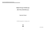
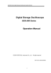
This help file explains the steps needed to set up and use an oscilloscope for
viewing and measuring CLASS waveforms.
Two types of oscilloscopes are discussed: The Tektronix TDS-220, a stand-alone
oscilloscope,
and the Link Instruments DSO 2102 and DSO 8500, both laptop-based
oscilloscopes. Each is pictured below.
TDS-220
(See Section 1
© 2006 Vapor Bus International
3
)
DSO 2102
(See Section 2
9
)
DSO 8500
(See Section 3
23
)
2
2
CLASS Oscilloscope Setup
Connections
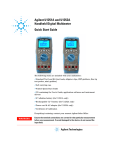
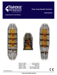
To use either oscilloscope, the oscilloscope probes must be connected to the
appropriate outputs. This requires use of an adapter cable which plugs into the
CLASS controller and provides the appropriate signals in a terminal strip suitable for
probe connections.
Typical connections are shown below (example shown is for measuring the LPS
sensor).
· Channel 1 (TDS-220) or Channel A1 (DSP 2102) is connected to LPS-S (LPS
Send)
· Channel 2 (TDS-220) or Channel A2 (DSP 2102) is connected to LPS-E (LPS
Echo)
· Note that GND and SHIELD may both be used for the probe GROUND
connections.
The other end of the adapter cable plugs into the CLASS controller at the connector
labeled "TEST" (J3).
© 2006 Vapor Bus International
TDS-220
3
TDS-220
3.1
Read First
3
For the following instructions, a TDS-220 3 will be used as a typical example. If a
different oscilloscope is used, the settings will still generally apply but the methods
required to achieve those settings may be different – consult the manual for the
oscilloscope in use.
The settings will be based on the assumption that Channel 1 is used for the signal
(connected to LPS, RPS, or MSU ECHO) and Channel 2 is used for the trigger
(connected to LPS, RPS, or MSU SEND).
Note: connect both probes to the oscilloscope before turning the oscilloscope on.
This will ensure that the proper probe settings are detected.
See Connections
3.2
2
.
Step 1: Setting the Trigger - Preliminary
1. Press the TRIGGER MENU
3
button
2. Using the Menu buttons (the buttons in a column directly to the right of the screen)
set as follows:
Edge
Type =
CH2
Source =
Rising
Slope =
Auto
Mode =
[Note: this setting will be changed later in step 5]
Coupling = DC
© 2006 Vapor Bus International
4
3.3
CLASS Oscilloscope Setup
Step 2: Setting the Time Base
1. Using the SEC/DIV 3 knob, set the time base to 2.50ms.
(This value can be observed in the text portion just below the graphical area of the
screen, following the CH1 and CH2 values.)
3.4
Step 3: Setting Channel 1(Echo)
1. Press the CH1 MENU
3
button
2. Using the Menu buttons (the buttons in a column directly to the right of the screen)
set as follows:
Coupling = Ground [Note: this setting will be changed later]
BW Limit = Off
Volts/Div = Coarse
1X (if probe is set to 1X) or 10X (if probe is set to 10X)
Probe =
Off
Invert =
3. Using the POSITION 3 knob for Channel 1, adjust the position of the horizontal
trace so that it is one division up from the bottom. (The correct trace will have a
"1" at its left side)
4. When step 3 is complete, change the Coupling
DC
3
(previously set to Ground) to
5. Using the VOLTS/DIV 3 knob for Channel 1, set to 1.00V ((This value can be
observed in the text portion just below the graphical area of the screen, following
the text "CH1".)
3.5
Step 4: Setting Channel 2 (Trigger)
1. Press the CH2 MENU
3
button
2. Using the Menu buttons (the buttons in a column directly to the right of the screen)
set as follows:
Coupling = Ground [Note: this setting will be changed later]
BW Limit = Off
Volts/Div = Coarse
1X (if probe is set to 1X) or 10X (if probe is set to 10X)
Probe =
Off
Invert =
3. Using the POSITION knob for Channel 2, adjust the position of the horizontal
trace so that it is one division down from the top. (The correct trace will have a "2"
at its left side)
© 2006 Vapor Bus International
TDS-220
5
4. When step3 is complete, change the Coupling (previously set in step 2 to Ground
) to DC
5. Using the VOLTS/DIV knob for Channel 2, set to 5.00V (This value can be
observed in the text portion just below the graphical area of the screen, following
the text "CH2".)
3.6
Step 5: Setting the Trigger - Final
1. Press the TRIGGER MENU
3
button
2. Using the Menu buttons (the buttons in a column directly to the right of the screen)
change settings (set in Setting the Trigger - Preliminary 3 ) as follows:
Mode = Normal
3. Using the LEVEL 3 knob (in the TRIGGER section), adjust for a value of
approximately 2.50V. (This value can be observed in the text portion of the
screen, just below the graphical area, on the right side. Any value between 1.00V
and 4.00V is acceptable; the goal is to be approximately in the middle of the
5-Volt trigger signal.)
3.7
Step 6: Troubleshooting
· If the expected waveforms are not seen, check the following:
1. Verify that the scope probes are correctly connected
2. Verify that the sensor being observed is actually on and transmitting.
· Verify that that the RUN/STOP 3 button is not in the STOP position – the word "
Trig'd" should be seen at the top of the screen.
3.8
Techniques
3.8.1
Time Measurement
3.8.1.1
Timing
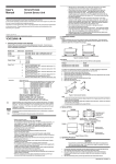
To measure the time to an echo:
1. Press the CURSOR 3 button on the scope. (This will change the menu items to
cursor-related selections, and change the VERTICAL POSITION knobs to
Cursor Position knobs)
2. Using the Menu 3 buttons, select:
Type
=
Time
Source
=
CH2
3. Using the Cursor 1 Position Knob), adjust Cursor 1 so that it lines up with the left
© 2006 Vapor Bus International
6
CLASS Oscilloscope Setup
edge of the trigger (See Scope Traces 7 )
When correctly alligned, the Cursor 1 Menu text will read "0.000s"
4. Using the Cursor 2 Position Knob, adjust Cursor 2 so that it lines up with the
point to be measured.
For an echo, line it up with the point where the leading (left-most) edge first
becomes greater than 2 volts.
5. The Cursor 2 Menu text will display the time from the trigger to the echo.
If the scope is set per Setting the Time Base 4 to 2.50 ms/Div, the time will be
in units of milliseconds (ms).
To calculate the distance to the echo:
1. Multiply the time found in step 5 above by 1000 (to convert to microseconds)
2. Divide the result by 59. The result is the distance in centimeters from the sensor
to the target.
Note: The number 59 is a constant that is based on the speed of sound in air at a
specific temperature (25 C or about 70 F).
If the actual temperature is different, the calculated distance may not be exactly the
same as the measured distance.
© 2006 Vapor Bus International
TDS-220
3.8.1.2
Scope Traces
3.8.2
Persistence
7
Persistence is a useful technique for measuring repetitive signals which vary over
time, and is especially useful in deciding when to include a potential target in the
CLASS target table. If Persistence is ON, each trace scan will be "added" to the
previous scan, allowing a build-up over time.
To use Persistence to detect targets, connect to the desired sensor, turn the sensor
on (using diagnostic test mode), and allow enough time for the scans to "build". If a
target appears only occasionally, with Persistence ON the trace will be stored and
the target will easily be seen.
To turn on persistence:
1. Press the scope's DISPLAY
Display properties.
3
button. This will change the menus to reflect
2. Press the MENU button adjacent to Persist.
© 2006 Vapor Bus International
8
CLASS Oscilloscope Setup
Each press of the button will cycle to the next option.
(Setting options are: Off, 1 Sec, 2 Sec, 5 Sec, and Infinite.)
The Persist value determines how long a signal is maintained on the screen for
viewing.
Setting to Infinite will allow monitoring of an echo over an extended period and will
capture the peak value for that period.
If a target's peak value is greater than 25% of the CLASS VREF Normal setting,
that target should be added to the target table.
(For the typical case of VREF Normal = 2.0V, any echo which peaks above 0.5V
should be added to the table.)
When finished using Persistence, remember to set it back to Off.
© 2006 Vapor Bus International
TDS-220
4
DSO 2102
4.1
Read First
9
For the following instructions, a DSO 2102 9 will be used as a typical example. If a
different oscilloscope is used, the settings will still generally apply but the methods
required to achieve those settings may be different – consult the manual for the
oscilloscope in use.
(Note: the colors shown in the examples may not be the same as those in your
configuration.)
The settings will be based on the assumption that Channel A1 is used for the ECHO
(connected to LPS, RPS, or MSU ECHO) and Channel A2 is used for the trigger
(connected to LPS, RPS, or MSU SEND).
See Connections
2
.
The DSO2102 may be used with a parallel connection or a USB connection.
© 2006 Vapor Bus International
10
CLASS Oscilloscope Setup
Although the parallel cable is larger, for maximum reliability it is suggested that the
parallel connection be used.
If the USB connection is used, follow this sequence:
1. Attach the probes to the DSO 2102 hardware box
2. Connect power to the DSO 2102 hardware box
3. Connect the USB cable to the DSO 2102 hardware box
4. Connect the USB cable to the laptop (it is important that this is the last
step)
Now the DSO 2102 software may be run.
If error messages regarding USB are seen, log out (or re-boot) and retry the
sequence.
If there still are USB problems (assuming Windows XP):
· Right-Click My Computer and select Properties.
· Select the Hardware tab, then click on Device Manager.
· Click on the + to the left of Universal Serial Bus Controllers to expand the list
· For each USB Root Hub:
- Right click and select Properties
- Select the Power Management tab
- Uncheck Allow the computer to turn off this device to save power
- Click OK
· When finished, close Device Manager
© 2006 Vapor Bus International
DSO 2102
4.2
11
DefaultSettings
Default Settings are automatically loaded each time the DSO 2102 9 software is
run. Once properly set (and Default Settings are saved) the program will be ready to
run thereafter without having to reload settings each time.
If "Auto save settings" is checked, any changes made will be saved to the Default
Settings when the program is closed. Click the "Auto save settings" menu item to
turn it on or off.
Once settings are saved as desired, un-check "Auto save settings" to prevent further
changes. It is also recommended that the same settings are saved to a second
location, such as Settings 5, in case default settings are changed inadvertently.
"Quick Save Settings" will save default settings or Settings 1 through Settings 5
"Quick Load Settings" will load any saved settings.
Once the DSO2102 is connected and the program is run, settings may be changed
as necessary if required.
When the desired settings are made, press
to begin sampling. Waveforms
similar to those shown in DSO 2102 9 should be seen.
Note: if the USB connection is used, it is highly recommended to press
closing the program.
© 2006 Vapor Bus International
before
12
4.3
CLASS Oscilloscope Setup
Channel A1 - Echo
Channel A1 is assumed to be used for ECHO.
Settings are as follows (see full screen here: DSO 2102
9
):
Note:
The Offset setting will determine where the trace "zero" lies. The Offset is related to
the Sensitivity (volts per division) and to the center of the display.
An Offset of -5.00 V, at 1V per division, will result in the trace zero-point baseline
being 5 divisions down from centerline.
© 2006 Vapor Bus International
DSO 2102
4.4
13
Channel A2 - Send
Channel A2 is assumed to be used for SEND.
Settings are as follows (see full screen here: DSO 2102
9
):
Note:
The Offset setting will determine where the trace "zero" lies. The Offset is related to
the Sensitivity (volts per division) and to the center of the display.
An Offset of 10.0 V, at 5V per division, will result in the trace zero-point baseline
being 2 divisions up from centerline.
© 2006 Vapor Bus International
14
4.5
CLASS Oscilloscope Setup
Timebase
The Timebase is set to 50 KSa as shown below (full screen here: DSO 2102
Use the
and
9
).
buttons to change the rate and thus change the Time per Division
The rate above is given in units of samples per second.
"50KSa" means 50,000 samples per second; the time per sample (NOT the Time
per Division) is the inverse: 1/50,000 = 20ms (microseconds).
Time per Division ("Time/div.") is displayed below the "Zoom" setting and is set to
1.00000mS
Also:
Set Memsize to 1K. This will provide faster screen refesh rates, and a more
"real-time" response.
© 2006 Vapor Bus International
DSO 2102
4.6
15
Trigger
Trigger settings are as follows (see full screen here: DSO 2102
9
):
Notes:
1. Channel A2 (SEND) is used as the trigger source.
2. The Level (2.60 V shown) may be anywhere in the 0V to 5V range of the SEND
pulse; near midpoint is usually best.
The trigger level may be seen graphically as a '+' on the right side of the screen,
relative to the designated channel.
© 2006 Vapor Bus International
16
4.7
CLASS Oscilloscope Setup
Time Cursors
Time Cursors (vertical cursors on horizontal axis) are set in the area below (see full
screen here: DSO 2102 9 ).
Notes:
1. The highlight colors shown above are those of the individual cursors on the scope
display (Cursor A is Green, etc.).
2. Cursor placement: The
and
buttons in the column labeled "100" will move
the cursor in large steps,
the "1" column is used for small steps.
Tip: the cursors may also be moved by click-and-drag.
3. On the right side of the cursor window, time measurements are displayed as
folows:
a. A-B: Time interval between Cursor A and Cursor B
b. A-T: Time interval between Cursor A and the Trigger Cursor
c. B-T: Time interval between Cursor B and the Trigger Cursor
To measure the time from the SEND pulse to an ECHO, position the Trigger Cursor
(Red) and Cursor A (Green)
as shown below (or on DSO 2102 9 ); A-T will then display the time (see above).
See Time Measurement 21 for details on converting a time measurement to the
distance to an Echo.
See Customizing 21 to have the DSO 2102 software automatically display distance
to the target.
© 2006 Vapor Bus International
DSO 2102
4.8
17
Voltage Cursors
Voltage Cursors (horizontal cursors on vertical axis) are set in the area below (see
full screen here: DSO 2102 9 ).
Notes:
1. The highlight colors shown above are those of the individual cursors on the scope
display (Cursor A is Green, etc.).
2. Cursor placement: Use the
and
buttons to move the chosen cursor to the
desired measurement position on screen.
Useful Tip: the cursors may also be moved by click-and-drag.
3. Voltage measurement:
a. Cursor A Voltage (Cur AVolt) in the Channel A1 column is referenced to the
zero-point baseline of Channel A1.
b. Cursor B Voltage (Cur BVolt) in the Channel A2 column is referenced to the
zero-point baseline of Channel A2.
Use those to measure the respective voltages.
The other measurements reference the respective cursor to the opposite channel's
© 2006 Vapor Bus International
18
CLASS Oscilloscope Setup
baseline.
In DSO 2102 9 , Cur Avolt (Channel A1) is being used to display the amplitude of
the small echo (0.96V),
Cur Bvolt (Channel A2) is displaying the amplitude of the SEND pulse (5.20V).
4. The A-B volt numbers shown measure the voltage between Cursor A and Cursor
B, and are calculated by multiplying the number of divisions between the cursors
by the volts/divison sensitivity of the respective channel.
© 2006 Vapor Bus International
DSO 2102
4.9
19
Saving Waveforms
Select File | Save to save waveforms. You can save as many waveforms as you
have harddisk space to accomodate.
If waveforms are saved as type "*.DSO", they will be viewable later with the DSO
2102 9 software even if it is not connected to the scope (running in Demo mode).
Saved *.DSO waveforms may be recalled, viewed, measured, and then re-saved as
*.CSV (which will allow direct importing into Excel).
© 2006 Vapor Bus International
20
4.10
CLASS Oscilloscope Setup
Techniques
4.10.1 Persistence
Persistence is a useful technique for measuring repetitive signals which vary over
time, and is especially useful in deciding when to include a potential target in the
CLASS target table. If Persistence is ON, each trace scan will be "added" to the
previous scan, allowing a build-up over time.
To use Persistence to detect targets, connect to the desired sensor, turn the sensor
on (using diagnostic test mode), and allow enough time for the scans to "build". If a
target appears only occasionally, with Persistence ON the trace will be stored and
the target will easily be seen.
Persistance may be turned on (or turned off) by clicking on the menu item as
shown.
RESULTS:
If a target's peak value is greater than 25% of the CLASS VREF Normal setting,
that target should be added to the target table.
(For the typical case of VREF Normal = 2.0V, any echo which peaks above 0.5V
should be added to the table.)
When finished using Persistence, remember to turn it OFF.
© 2006 Vapor Bus International
DSO 2102
21
4.10.2 Time Measurement
To measure the time to an echo:
Adjust the Time Cursors as discussed in the Time Cursors 16 section. Read the
resultant A-T value. (Readings should be in milliseconds.)
To calculate the distance to the echo:
1. Multiply the time in milliseconds found above by 1000 (to convert to
microseconds)
2. Divide the result by 59. The result is the distance in centimeters from the sensor
to the target.
Note: The number 59 is a constant that is based on the speed of sound in air at a
specific temperature (25 C or about 70 F).
If the actual temperature is different, the calculated distance may not be exactly the
same as the measured distance.
To directly display the distance to the echo:
Adjust the Time Cursors as discussed in the Time Cursors
Customizing 21 to change the display to centimeters.
16
section. Refer to
4.10.3 Customizing
Time measurements can be customized to directly display distance (to a target) in
centimeters as follows:
1. Select View | Samples or Time | Setup Custom...
© 2006 Vapor Bus International
22
CLASS Oscilloscope Setup
2. Enter 16949.152 in the "Multiplier" box and cm in the "Units" box. Click OK.
3. If Display Custom is selected, the Time Display will show centimeters to the target
(if the cursor is on the target) as shown.
To see time units, select Display Time instead.
Result:
4. Once the file is saved, the Custom Settings will be saved as well.
© 2006 Vapor Bus International
DSO 8500
5
DSO 8500
5.1
Read First
23
For the following instructions, a DSO 8500 23 will be used as a typical example. If a
different oscilloscope is used, the settings will still generally apply but the methods
required to achieve those settings may be different – consult the manual for the
oscilloscope in use.
(Note: the colors shown in the examples may not be the same as those in your
configuration.)
The settings will be based on the assumption that Channel A1 is used for the ECHO
(connected to LPS, RPS, or MSU ECHO) and Channel A2 is used for the trigger
(connected to LPS, RPS, or MSU SEND).
See Connections
2
.
The DSO 8500 is only used with a USB connection.
© 2006 Vapor Bus International
24
CLASS Oscilloscope Setup
LED Functions:
The Red LED is ON when:
1. The DSO is connected, and
2. The DSO is powered, and
3. The software is running
Yellow LED:
1. Blinks 4 times at selftest completion
2. Is ON when DSO is in acquisition mode
© 2006 Vapor Bus International
DSO 8500
5.2
25
DefaultSettings
Default Settings are automatically loaded each time the DSO 8500 23 software is
run. Once properly set (and Default Settings are saved) the program will be ready to
run thereafter without having to reload settings each time.
If "Auto save settings" is checked, any changes made will be saved to the Default
Settings when the program is closed. Click the "Auto save settings" menu item to
turn it on or off.
Once settings are saved as desired, un-check "Auto save settings" to prevent further
changes. It is also recommended that the same settings are saved to a second
location, such as Settings 5, in case default settings are changed inadvertently.
"Quick Save Settings" will save default settings or Settings 1 through Settings 5
"Quick Load Settings" will load any saved settings.
Once the DSO8500 is connected and the program is run, settings may be changed
as necessary if required.
When the desired settings are made, press
to begin sampling. Note:
since the USB connection is used, it is highly recommended to press
before closing the program.
© 2006 Vapor Bus International
26
5.3
CLASS Oscilloscope Setup
Channel A1 - Echo
Channel A1 is assumed to be used for ECHO.
Settings are as follows (see full screen here: DSO 8500
23
):
Note:
The Offset setting will determine where the trace "zero" lies. The Offset is related to
the Sensitivity (volts per division) and to the center of the display.
An Offset of -4.00 V, at 1V per division, will result in the trace zero-point baseline
being 4 divisions down from centerline.
© 2006 Vapor Bus International
DSO 8500
5.4
27
Channel A2 - Send
Channel A2 is assumed to be used for SEND.
Settings are as follows (see full screen here: DSO 8500
23
):
Note:
The Offset setting will determine where the trace "zero" lies. The Offset is related to
the Sensitivity (volts per division) and to the center of the display.
An Offset of 20.0 V, at 5V per divison, will result in the trace zero-point baseline
being 4 divisions up from centerline.
© 2006 Vapor Bus International
28
5.5
CLASS Oscilloscope Setup
Timebase
The Timebase is set to 50 KSa as shown below (full screen here: DSO 8500
Use the
and
23
).
buttons to change the rate and thus change the Time per Division
The rate above is given in units of samples per second.
"50KSa" means 50,000 samples per second; the time per sample (NOT the Time
per Division) is the inverse: 1/50,000 = 20ms (microseconds).
Time per Division ("Time/div.") is displayed below the "Zoom" setting and is set to
1.00000mS
Also:
Set Memsize to 8K. This will provide faster screen refesh rates, and a more
"real-time" response.
© 2006 Vapor Bus International
DSO 8500
5.6
29
Trigger
Trigger settings are as follows (see full screen here: DSO 8500
23
):
Notes:
1. Channel A2 (SEND) is used as the trigger source.
2. The Level (2.60 V shown) may be anywhere in the 0V to 5V range of the SEND
pulse; near midpoint is usually best.
The trigger level may be seen graphically as a dashed horizontal red line.
© 2006 Vapor Bus International
30
5.7
CLASS Oscilloscope Setup
Time Cursors
Time Cursors (vertical cursors on horizontal axis) are set in the area below (see full
screen here: DSO 8500 23 ).
Notes:
1. The highlight colors shown above are those of the individual cursors on the scope
display (Cursor A is Green, etc.).
2. Cursor placement: The
and
buttons in the column labeled "100" will move
the cursor in large steps,
the "1" column is used for small steps.
Tip: the cursors may also be moved by click-and-drag.
3. On the right side of the cursor window, time measurements are displayed as
folows:
a. A-B: Time interval between Cursor A and Cursor B
b. A-T: Time interval between Cursor A and the Trigger Cursor
c. B-T: Time interval between Cursor B and the Trigger Cursor
To measure the time from the SEND pulse to an ECHO, position the Trigger Cursor
(Red) and Cursor A (Green)
as shown below (or on DSO 8500 23 ); A-T will then display the time (see above).
See Time Measurement 21 for details on converting a time measurement to the
distance to an Echo.
See Customizing 21 to have the DSO 8500 software automatically display distance
to the target.
© 2006 Vapor Bus International
DSO 8500
5.8
31
Voltage Cursors
Voltage Cursors (horizontal cursors on vertical axis) are set in the area below (see
full screen here: DSO 8500 23 ).
Notes:
1. The highlight colors shown above are those of the individual cursors on the scope
display (Cursor A is Green, etc.).
2. Cursor placement: Use the
and
buttons to move the chosen cursor to the
desired measurement position on screen.
Useful Tip: the cursors may also be moved by click-and-drag.
3. Voltage measurement:
a. Cursor A Voltage (Cur AVolt) in the Channel A1 column is referenced to the
zero-point baseline of Channel A1.
b. Cursor B Voltage (Cur BVolt) in the Channel A2 column is referenced to the
zero-point baseline of Channel A2.
Use those to measure the respective voltages.
The other measurements reference the respective cursor to the opposite channel's
© 2006 Vapor Bus International
32
CLASS Oscilloscope Setup
baseline.
In DSO 8500 23 , Cur Avolt (Channel A1) is being used to display the amplitude of
the small echo (0.96V),
Cur Bvolt (Channel A2) is displaying the amplitude of the SEND pulse (5.20V).
4. The A-B volt numbers shown measure the voltage between Cursor A and Cursor
B, and are calculated by multiplying the number of divisions between the cursors
by the volts/divison sensitivity of the respective channel.
© 2006 Vapor Bus International
DSO 8500
5.9
33
Saving Waveforms
Select File | Save data and settings to save waveforms. You can save as many
waveforms as you have harddisk space to accomodate.
Waveforms are saved as type "*.DSO", and will be viewable later with the DSO 8500
23 software even if it is not connected to the scope (running in Demo mode).
Saved *.DSO waveforms may be recalled, viewed, measured, and then exported as
*.CSV (which will allow direct importing into Excel).
© 2006 Vapor Bus International
34
6
CLASS Oscilloscope Setup
Revisions
Revision List
3.0: Added DSO 8500 section
© 2006 Vapor Bus International