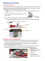
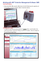
1
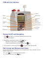
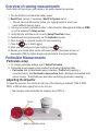
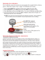
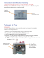
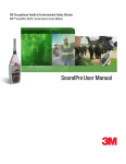
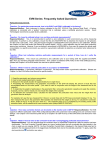
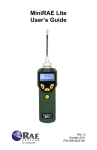
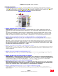
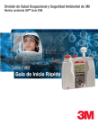
3M Personal Safety Division
3MTM EVM Series Environmental Monitor
EVM Series
Quick Start Guide
EVM and User Interface
Indicators
Display
Softkey menus
Backlight
Up arrow key
Altf key
Enter key
Particulate
pump
Right arrow key
Down arrow key
Left arrow key
On/Off and
Esc key
Run/Stop key
Turning On/Off and Navigating
1. Press
key power on. (Following a splash/welcome screen, the
Start screen will appear.)
2. Navigating to measurement screens - press
keys.
• Navigating to menu options - press
keys.
• To open a selected menu or to save settings - press
3. In the powered on mode, press and hold
key.
key to power down the instrument.
Start Screen and Measurement Views
You will visit the start screen frequently to access measurements, setup, calibration, unit info,
and file system screens. ;;
Press
keys to access the measurements screens.
;; To select a menu option, press
keys.
Overview of running measurements
Quick Help List: typical gas, particulates,or air quality measuring overview
1. Turn the EVM on and check the battery power.
2. Reset/Clear memory, if necessary (Start\File System menu).
• This will clear out data history before your logging begins to ensure you
have sufficient memory space.
3. Set-up your session parameters either in 3MTM Detection Management Software (DMS)
or via the instrument’s Setup screen.
4. Verify the time and date is set correctly (Setup\Time-Date menu).
5. Calibrate each sensor/parameter via the Calibration screen.
6. Place the EVM in a specific location for area monitoring.
7. Press the
key to Start logging.
8. When you are ready to end your logging, press
key.
9. Review your results either on the instrument (via the File System screen) or
download to DMS for further analysis (graphs/charts, saving and printing).
Particulate Measurements
Particulate setup
1. To change particulate settings select: Setup\Particulate.
2. Particulate screen appears and includes the following adjustable fields: • Particulate field (enable/disable pump collection), Profile field (applying a
correction factor), and Gravimetric mass/volume fields (displays accumulated mass
and air volume. These fields are reset when performing gravimetric sampling.)
Adjusting the Impactor
To adjust the impactor, turn the turret until one of the following is selected: PM2.5, PM4,
PM10, or PM (all dust ranging from 0 μm-100 μm).
•The example below illustrates the impactor set to PM 2.5.
PM 2.5
Align to impactor arrow
Particulate Zero Calibration
Prior to calibrating, ensure the impactors are well-greased with an applied thin-film of silicone
grease. (Please see “Impactor Care” on page 10 or EVM series user manual.)
1.
2.
3.
4.
Attach the Zero/HEPA filter and tubing into the turret. Rotate the turret to PM.
Select Calibration from the Start screen and select PM (using up/down arrows).
Press Cal softkey and then press Start softkey. Once level is stabilized, press Set softkey.
Once level has been set, you can press Save or Cancel. (Please refer to Chapter 4 of
EVM series manual for more information.)
;; NOTE: Once saved, the instrument will apply the zero calibration to all profiles. The zero calibration is
stored in the History screen and a calibration. Verify can be performed (to ensure no drifting).
Zero/HEPA filter example
Used for particulate zero cal.
Tubing and vent opening
Insert tubing into the impactor of the
labeled “2.5” vent opening
Turret
Turn the turret so “PM” appears on the
display of the EVM.
Particulate Advanced Calibration (Gravimetric)
Gravimetric Calibration Overview
(1)Reset the gravimetric and volume accumulators; (2) Insert a new (sealed) gravimetric cassette; (3)
Measure in the specific location for approximately four to eight hours; (4) Record the value displayed in
the gravimetric accumulator field displayed in the particulate screen. (This value is used in conjunction
with the weight of the measured dust in the cassette.); (5) Remove the gravimetric cassette and weigh the
filtered contents. (Typically, send to a lab for results.); (6) To determine the correction factor, calculate the
ratio between the particulate mass value and the weight from the gravimetric filter lab analysis. (Ratio = true
weight/EVM gravimetric displayed value). (7) Enter user correction value (Setup\Particulate screen. Select
profile field and then press Edit softkey. Add Factor using up/down arrows. Press On/OFF/Esc key twice to
return to start screen.)
Logging Particulates
1. Before logging particulates, ensure the impactors are clean and well-greased.
2. From the start screen or any measurement screen, press
key.
3. Press
key to end the logged session. (See “Viewing logged results” to access past
sessions.)
Volatile Organic Compounds (VOCs)
VOCs, air pollution with carbon-containing chemicals, are measured using a
Photoionization detector 10.6eV. The EVM is equipped to notify you when
maintenance and cleaning is required for the PID sensor. A PID sensor
error will appear indicating:
(1) if the sensor needs to be cleaned, or (2) the lamp needs replacing.
PID Zero Calibration
The PID ppm zero calibration preferred method is to flush with Zero Grade Air. Alternatively,
Nitrogen may be used. For best response time, it is recommended to set the flow rate at 1
LPM. NOTE: Please refer to the EVM series manual for more information on the PID ppm/
ppb sensors.
1. Connect the Zero Grade Air, tubing, and cal. cup to the EVM. (Please skip
this step if you are not applying a gas.)
2. Select Calibration from the Start screen and select PID (using up/down arrows).
3. Press Cal softkey and then press Zero softkey. Once level is stabilized, press Set
softkey. (Typically takes 60 seconds to stabilize.)
4. Once level has been set, you can press Save or Cancel. (Disconnect components
and return to the start screen via On/Off/Esc key.)
PID Span Calibration
Typically, Isobutylene is used when the VOCs are unknown. NOTE: in order to measure
specific VOCs, you will want to use the relevant VOC for your calibrated gas source for a
ppm/ppb sensors. (Please refer to the manual for PID correction factor table; Appendix C for details.)
1. Connect Isobutylene, regulator, tubing and cal cap to the EVM.
2. Follow steps 2-4 above (in PID Zero Cal. section) but select Span softkey instep 3.
Logging VOCs
1. From the start screen or any measurement screen, press
•
key.
To view VOCs measurements, select either the Gas or Composite screen by pressing
from the start screen.
2. Press
keys
key to stop logging. (See “Viewing logged results” to access past sessions.)
Run icon
PID sensor
measurement
Gas measurement
screen
Toxic Gases
The following toxic gases table displays a quick overview of the ranges and the gases needed to perform zero and
span calibrations.
Type of Gas
Carbon Monoxide (CO)
Range
Res.
Zero cal
gas
Span cal
gas
0 -1000 ppm
1 ppm
nitrogen/pure air
CO
Chlorine (CL2)
0.0 - 20 ppm
0.1 ppm
nitrogen/pure air
CL2
Ethylene Oxide (EtO)
0.0 - 20 ppm
0.1 ppm
nitrogen/pure air
EtO
Hydrogen Cyanide (HCN)
0.0 - 50 ppm
0.1 ppm
nitrogen/pure air
HCN
1 ppm
nitrogen/pure air
H2S
Hydrogen Sulfide (H2S)
0 - 500 ppm
Nitrogen Dioxide (NO2)
0.0 - 50 ppm
0.1 ppm
nitrogen/pure air
NO2
Nitric Oxide (NO)
0.0 - 100 ppm
0.1 ppm
nitrogen/pure air
NO
Oxygen (O2)
0.0 - 30%
0.1%
nitrogen
Room air
Sulphur Dioxide (SO2)
0.0 - 50 ppm
0.1 ppm
nitrogen/pure air
SO2
*1.0 L/min. flow rate
*span 20.9%
Carbon Dioxide Gas
Similar to toxic gases, the carbon dioxide sensor should be calibrated prior to logging.
Toxic and Carbon Dioxide Zero Calibration
Depending on the gas of interest, the toxic zero calibration is performed with the gas indicated in the table above.
The CO2 sensor requires a calibration gas, a regulator with at least 1.0 Liter/minute flow rate, and a hose/tubing. Nitrogen (N2) is the recommended gas for a zero calibrating (If you are not applying a gas, start at step 2.)
1. Connect the appropriate gas/pure air, regulator, tubing, and cal. cup to the EVM.
2. Select Calibration from the Start screen and choose a specific toxic using keys. (i.e., CO).
3. Press Cal softkey and then press Zero softkey. Once level is stabilized, press Set softkey. (Allow at least 90
seconds to stabilize.)
4. Press Save or Cancel softkey to store the process. Disconnect components and return to the start screen via
On/Off/Esc key.
Cal. cup/adapter
Tubing
Regulator
Cal. gas source
Toxic and Carbon Dioxide Span Calibration
To perform a span calibration with a specific toxic gas, please reference the toxic gas
table. For the CO2 span calibration, the range (or span) should be a sizeable fraction of the
selected full scale range of the gas.
;; NOTE: The range for the CO2 sensor is 0 to 5,000 ppm. For a span calibration, it is recommended
to span cal to the value you will be measuring (i.e., 2,000 ppm).
1. Connect the appropriate gas, regulator, tubing and cal cap to the EVM.
2. Follow steps 2-4 above (in Toxic Zero Calibration section) but select Span softkey in
step 3. (NOTE: For Oxygen span calibration, the typical span is 20.9%.)
Logging Toxic Gases or Carbon Dioxide
1. From the Start screen or any Measurement screen, press
key.
• To view gas measurements, select either the Gas or Composite screens
(by pressing
from the start screen when Setup is selected.)
2. Press
key to stop logging. (See “Viewing logged results” to access past sessions.)
Run Icon
CO2 value
Toxic (CO)
value
Composite
Measurement screen
Particulate advanced calibration (Gravimetric filtering)
Gravimetric Calibration Overview
(1)Reset the gravimetric and volume accumulators; (2) Insert a new (sealed) gravimetric
cassette; (3) Measure in the specific location for approximately four to eight hours; (4)
Notate the value displayed in the gravimetric accumulator field (displayed in the particulate
screen. (This value is used in conjunction with the weight of the measured dust in the
cassette.); (5) Remove the gravimetric cassette and weigh the filtered contents. (Typically,
sent to a lab for results.); (6) To determine the correction factor, calculate the ratio between
the particulate mass value and the weight from the gravimetric filter lab analysis.
Measuring particulates
1. From the start screen or any measurement screen, press the
key. (Prior to
logging, a 5 second count-down appears.)
2. Press
key to end the logged session. (See “Viewing logged results” to view past
sessions.)
Temperature and Relative Humidity
Logging/Viewing Temperature and/or Relative Humidity
The Temperature and Relative Humidity readings are viewable in either the Temp-RH
measurement screen or in the Composite screen.
Temp/RH
measurements
Temp/RH
measurement screen
Particulate Air Flow
Calibration
For Airflow meter calibration, an accurate flow meter (such as a primary standard
calibrator) and tubing is required.
1.
2.
3.
4.
Attach the primary standard calibrator tubing to the air flow outlet.
Navigate to the Setup\Calibration\Flow RT (rate) screen.
Press the Cal softkey and then press Start softkey.
Adjust the flow rate (using the up and down arrow keys) so the primary standard
calibrator is 1.67 LPM and then confirm by pressing the Save softkey.
;; NOTE: It should be noted that in order for the impactors to work properly the flow rate must be
adjusted to 1.67 LPM.
AirProbe inlet
with attachment
Air Flow Outlet
*To calibrate, connect
primary standard
calibrator with tubing
Air Velocity
To view air velocity measurements, perform or verify the following:
1. The air velocity probe is enabled in Setup\AUX\Air Velocity screen.
2. Connect the air velocity probe and attachment to the EVM unit to the auxiliary
Air probe inlet.
(See Air Probe inlets diagram in previous section, “Particulate Air Flow”.)
3. Turn Air Velocity Probe switch On.
4. Navigate to the Air Velocity measurement screen using
keys.
Connect AirProbe to the back housing (two inlets
located near the air flow outlet. See air flow diagram
on previous page.)
Air velocity measurement screen
Viewing Logged sessions (past sessions)
Once you have logged data and stopped the session, the data is stored under the
past session summary menu. (Optional: you can view the data in charts/graphs when
downloaded to DMS.)
1. Navigate to Start \Past Session screen.
2. Select the File field and press the File softkey. (Past Session\Load File screen
will display all of the logged files.) Press Enter key to change between different file
views.
3. Select the appropriate file (by using up/down arrows) and press the Load softkey
4. Press Detail softkey to view data.
5. Press
keys to view summary data. Repeat as necessary.
Session Run Time
Summary session
Maintenance/Cleaning
Sensors Locations
The gas sensors are inserted, factory calibrated, and ready for usage upon delivery. (The
diagram below is based on the EVM-7 model.) Occasionally , you may have to care for
the sensors which will require removing and inserting.
;; NOTE: Verify the unit is off and unplugged from the power cord before removing or inserting
sensors.
1. Remove the sensor bar (via the screws) and remove
the manifold.
Manifold
2. Sensor bar removal and location of sensors are displayed below.
• When removing/inserting, align the socket pins to the circuit board accordingly.
Sensor bar - Remove screw 1 & 2 and lift off cover
Screw 1
Screw 2
PID sensor
Toxic sensor
CO2 sensor
Impactor Care and Particulates
The impactor requires periodic greasing and cleaning for particulate measuring only.
1. Remove the turret (red housing cover over the impactor) by removing the right
and left screw with the supplied allen wrench (stored behind the access door.)
2. Remove all debris/dust with a Q-tip/cotton.
3. Wipe a very thin film of silicone grease onto the metal plates using a Q-tip/cotton.
4. Re-attach by placing the turret cover over the housing and tighten screws.
Thin-layer of
silicone is applied to a
clean impactor.
Example of
accumulated dust
(will form into a pyramid)
Working with 3MTM Detection Management Software DMS
Communicating
1. When the EVM is On, plug the USB cable into the EVM and plug the opposite end
to the USB port of your computer. (Refer to illustration below.)
Viewing your data
In DMS once your files are downloaded via Download button, view the data in the
panel layout view or reports by clicking on appropriate buttons. See an example of
the panel layout page below.
Personal Safety Division
3M Detection Solutions
ISO 9001 Registered Company
ISO 17025 Accredited Calibration Lab
1060 Corporate Center Drive
Oconomowoc, WI 53066
Customer Service: 262-567-9157
Toll Free: 800-245-0779
www.3M.com/detection
3M is a trademark of 3M Company,
used under license in Canada.
Please recycle. Printed in USA.
© 2013 3M. All rights reserved.
074-301, Rev.D. 4/13