1
DB-Main Manual Series
MDL PROGRAMMER ’S GUIDE
VERSION 6.5 - MARCH 2002
The University of Namur - LIBD
ii
CONTENTS
CONTENTS ............................................................................................................................................... III
CHAPTER 1
INTRODUCTION ...................................................................................................................1
CHAPTER 2
MDL DEVELOPMENT ENVIRONMENT .................................................................................3
2.1
2.2
2.3
The text window ............................................................................................................................................ 4
The graphical window ................................................................................................................................... 4
Menus and toolbar ......................................................................................................................................... 4
2.3.1
File menu......................................................................................................................................... 4
2.3.2
Edit menu ........................................................................................................................................ 4
2.3.3
Search menu .................................................................................................................................... 5
2.3.4
MDL menu ...................................................................................................................................... 5
2.3.5
View menu....................................................................................................................................... 5
2.3.6
Window menu ................................................................................................................................. 5
2.3.7
Help menu ....................................................................................................................................... 5
2.3.8
Title contextual menu ...................................................................................................................... 5
2.3.9
Primitive process type contextual menu.......................................................................................... 5
2.3.10 Engineering process type contextual menu ..................................................................................... 5
2.3.11 Decision contextual menu ............................................................................................................... 6
2.3.12 Product type contextual menu ......................................................................................................... 6
2.3.13 Toolbar............................................................................................................................................. 6
CHAPTER 3
BASIC CONCEPTS ................................................................................................................7
3.1
3.2
Basic definitions ............................................................................................................................................ 7
About the MDL language.............................................................................................................................. 9
3.2.1
Forward referencing ...................................................................................................................... 10
3.2.2
Comments...................................................................................................................................... 10
CHAPTER 4
METHOD ...........................................................................................................................11
CHAPTER 5
PRODUCT MODELS ...........................................................................................................13
5.1
5.2
Schema model description........................................................................................................................... 14
5.1.1
Constraints..................................................................................................................................... 15
5.1.2
Schema model description syntax ................................................................................................. 25
Text model description ................................................................................................................................ 27
5.2.1
Defining a grammar: the PDL language........................................................................................ 27
5.2.2
The text model description syntax ................................................................................................ 29
iv
CHAPTER 6
GLOBAL PRODUCT TYPES ................................................................................................ 31
CHAPTER 7
TOOLBOXES AND EXTERNAL FUNCTIONS ......................................................................... 33
7.1
7.2
Toolbox ........................................................................................................................................................33
External function declarations .....................................................................................................................34
CHAPTER 8
PROCESS TYPES................................................................................................................ 37
8.1
8.2
8.3
8.4
8.5
8.6
Engineering process type decomposition ....................................................................................................37
The process description ...............................................................................................................................39
Formal parameters .......................................................................................................................................40
8.3.1
Parameter properties ......................................................................................................................40
8.3.2
Using parameters ...........................................................................................................................41
Local product types......................................................................................................................................42
Product sets ..................................................................................................................................................43
The strategy..................................................................................................................................................43
8.6.1
Graphical conventions ...................................................................................................................43
8.6.2
The sequence .................................................................................................................................44
8.6.3
The while structure ........................................................................................................................44
8.6.4
The repeat...until structure .............................................................................................................45
8.6.5
The repeat structure .......................................................................................................................47
8.6.6
The if...then...else structure............................................................................................................47
8.6.7
The one, some, each structures ......................................................................................................48
8.6.8
The for structure ............................................................................................................................48
8.6.9
Sub-process calls ...........................................................................................................................50
8.6.10 Built-in procedures ........................................................................................................................54
8.6.11 Expressions ....................................................................................................................................57
8.6.12 Miscellaneous ................................................................................................................................59
CHAPTER 9
HISTORY .......................................................................................................................... 61
9.1
9.2
9.3
Basic elements .............................................................................................................................................61
Structure.......................................................................................................................................................62
9.2.1
The complexe structure..................................................................................................................62
9.2.2
Derived structures..........................................................................................................................62
9.2.3
Graphical presentation ...................................................................................................................62
Building an history while using a method ...................................................................................................64
9.3.1
Primitive processes ........................................................................................................................65
9.3.2
Engineering processes ...................................................................................................................65
9.3.3
Hypotheses, versions and decisions...............................................................................................66
CHAPTER 10
A FEW METHODOLOGICAL ELEMENTS ............................................................................. 67
10.1
10.2
10.3
Product model declarations..........................................................................................................................67
Product type declarations.............................................................................................................................68
Process type declarations .............................................................................................................................69
10.3.1 Loops .............................................................................................................................................69
10.3.2 Sequences and each structures.......................................................................................................71
10.3.3 Process use.....................................................................................................................................73
10.3.4 Degrees of freedom........................................................................................................................74
BIBLIOGRAPHY........................................................................................................................................ 79
APPENDIX A
THE MDL SYNTAX.......................................................................................................... 81
v
A.1
A.2
A.3
A.4
A.5
A.6
A.7
A.8
A.9
A.10
A.11
BNF notation ............................................................................................................................................... 81
Miscellaneous rules ..................................................................................................................................... 81
Multi-purpose definitions ............................................................................................................................ 82
Method description ...................................................................................................................................... 82
External declaration..................................................................................................................................... 83
Expressions.................................................................................................................................................. 83
Schema model description........................................................................................................................... 84
Text model description ................................................................................................................................ 84
Product type description .............................................................................................................................. 84
Toolbox description ..................................................................................................................................... 85
Process type description .............................................................................................................................. 85
APPENDIX B
PREDICATES .....................................................................................................................89
B.1
B.2
B.3
B.4
B.5
B.6
B.7
B.8
B.9
B.10
B.11
B.12
B.13
B.14
B.15
B.16
B.17
Constraints on schema................................................................................................................................. 89
Constraints on collections............................................................................................................................ 89
Constraints on entity types .......................................................................................................................... 90
Constraints on is-a relations ........................................................................................................................ 93
Constraints on rel-types ............................................................................................................................... 94
Constraints on roles ..................................................................................................................................... 96
Constraints on attributes .............................................................................................................................. 96
Constraints on groups .................................................................................................................................. 98
Constraints on entity type identifiers......................................................................................................... 100
Constraints on rel-type identifiers ............................................................................................................. 102
Constraints on attribute identifiers ............................................................................................................ 105
Constraints on access keys ........................................................................................................................ 107
Constraints on referential groups............................................................................................................... 108
Constraints on processing units ................................................................................................................. 110
Constraints on names................................................................................................................................. 110
Using Voyager 2 constraints ...................................................................................................................... 113
Using DYN_PROP_OF_... constraints ..................................................................................................... 113
APPENDIX C
GLOBAL TRANSFORMATIONS .........................................................................................115
C.1
C.2
Transformations......................................................................................................................................... 115
Control structures ...................................................................................................................................... 117
APPENDIX D
DB-MAIN TOOLS ..........................................................................................................119
vi
Chapter 1
Introduction
MDL is a Method Description Language aimed at defining methods for analysts to perform any database engineering work using the DB-MAIN CASE tool. This book is intended to method engineers,
that is to say to the persons who have to define methods that will be integrated into the DB-MAIN
CASE tool.
The second chapter describes the basic notions that underlies the language. Chapter 3 to 7 depict in
details the syntax of the different parts of the language. Chapter 8 presents a few generalities about histories in the DB-MAIN CASE tool, these histories being a complex log of a work. Chapter 9 briefly
explains how a database engineer can use a method to do his or her job for which an history will be
build. Finally, chapter 10 will give a few advices to method engineers on how to build a method that
will be usable by database engineers, knowing how they have to work.
2
Chapter 1 Introduction
Chapter 2
MDL development environment
This book is a complete reference about writing a method in the MDL language for use by the DBMAIN CASE tool. In this chapter, we will present a simple development environment which allows a
method engineer to edit an MDL file, to compile it, and to generate a .LUM file usable by the DBMAIN CASE tool.
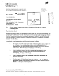
Figure 2.1 shows a common view of the environment. It is a traditional Windows application with a title
bar, a menu, a small tool bar, a status bar in the bottom and two windows. The textual window contains
an MDL source file, and the graphical windows shows the graphical representation of the method from
the first window. We will examine all these components in more details.
Figure 2.1 - The MDL development environment
4
Chapter 2 MDL development environment
2.1 The text window
The text window is a simple text editor with traditional basic editing functions (copy, cut, paste, undo).
For more advanced editing functions such as auto-indent, parenthesis-checking and so on, the user may
use another third-party text editor for edition and reload his or her texts in this window for compilation.
When this window is active, you can click on the “MDL/Compile” menu entry to compile the text. If it
is syntactically correct, a graphical window appears to show the result of the compilation. If an error
occurs, a message box shows the error message and selects the faulty line in the text editor.
A second compilation of a same text will reuse the same graphical window.
You can open several text files at the same time. Each text file, when compiled, will have its associated
graphical window.
2.2 The graphical window
A graphical window contains the result of a compilation of the content of a text window, that is a graphical representation of a database engineering method. The user can browse through the whole method
by clicking with the right mouse button on the rectangles and the ellipses to make a menu appear and
clicking on the entries of this menu. Rectangles represent process types, ellipses represent product
types. The signification of these notions and their graphical representation will appear more clearly
withe the following chapters. The content of this window is not editable.
2.3 Menus and toolbar
2.3.1 File menu
File/New: Creates a new blank text window. Always available.
File/Open: Opens a text file in a new text window. Always available.
File/Save: Saves the current text window. Only available when a text window is active.
File/Save As...: Saves the current text window with a new file name. Only available when a text window is active.
File/Generate LUM: Generates a .LUM file with the content of the current graphical window. Only
available when a graphical window is active.
File/Import LUM: Opens a .LUM file for viewing only in a new graphical window. Always available.
File/Print Preview...: Previews of a printing of the current window. Available when either a text or a
graphical window is active.
File/Print...: Prints the content of the current window. Available when either a text or a graphical window is active.
File/Print Setup...: Sets the printing parameters for the next printing or preview. Available when either a
text or a graphical window is active.
File/Exit: Closes all windows and exit the development environment. If a text window contains
unsaved modifications, a request for saving will automatically be prompted. Always available.
2.3.2 Edit menu
Edit/undo: In a text window, undoes the last modification. In a graphical window, same effect as the
’Back’ menu entry in the contextual menu of the process title. Available when either a text or a
graphical window is active.
Edit/Cut: Removes the selected text and put it in the clipboard. Available in a text window only.
Edit/Copy: In a text window, copies the selected text to the clipboard. In a graphical window, copies the
whole drawing in the clipboard. Available when either a text or a graphical window is active.
Edit/Paste: Copies the content of the clipboard, if it is a text, to the current text editor. Available when a
text window is active only.
2.3 Menus and toolbar
5
Edit/Clear All: Clears the content of the current text window. Available when a text window is active
only.
Edit/Delete: Removes the selected text or the character at the right of the cursor in a text. Available
when a text window is active only.
2.3.3 Search menu
Search/Find...: Searches for a few characters in the current text. Only available when a text window is
active.
Search/Replace...: Searches for a few characters in the current text and replaces them by other characters. Only available when a text window is active.
Search/Next: Repeat the last search or replace. Only available when a text window is active and if a
search or a replace already took place.
2.3.4 MDL menu
MDL/Compile: Compiles the content of the current text window. Only available if a text window is
active.
2.3.5 View menu
View/Show product types: Shows or hides the product types in the current graphical window. Only
available when a graphical window is active.
View/Show titles: Shows the tiles of the process types in the current graphical window. Only available
when a graphical window is active.
View/Show identifiers: Shows the identifying names of the process types in the current graphical window. Only available when a graphical window is active.
2.3.6 Window menu
Window/Cascade, Window/Tile, Window/Close All: traditional menu entries.
2.3.7 Help menu
Help/About...: "About" dialogue box with application version.
2.3.8 Title contextual menu
The title is the rectangle inside the gray area at the top of a graphical window.
Back: Shows the graphical view of the parent engineering process type. This is the reverse of the
’Open’ menu entry in the contextual menu of an engineering process type.
Properties: Shows the properties and description of the current engineering process type. Shortcut:
double-click on the title.
2.3.9 Primitive process type contextual menu
A primitive process type is a rectangle in a graphical window. It looks like an engineering process type.
Properties: Shows the properties and description of the selected primitive procvess type. Shortcut: double-click on the selected primitive process type.
2.3.10 Engineering process type contextual menu
An engineering process type is a rectangle in a graphical window. It looks like a primitive process type.
Expand here: Shows or hides the complete view of the selected engineering process type, surrounded
by dashes, in place of its title in the current engineering process type view.
Expand below: Shows or hides the complete view of the selected engineering process type at the bottom of the current engineering process type view.
Open: Replaces the view of the current engineering process type by the view of the selected engineering process type. Shortcut: double-click on the selected engineering process type.
6
Chapter 2 MDL development environment
Properties: Shows the properties and description of the selected engineering process type.
2.3.11 Decision contextual menu
A decision is a diamond in a graphical window.
Properties: Shows the properties and description of the selected decision. Shortcut: double-click on the
selected decision.
2.3.12 Product type contextual menu
A product type is an ellipse in a graphical window.
Properties: Shows the properties and description of the selected product type. Shortcut: double-click on
the selected product type.
2.3.13 Toolbar
Same as menu entry “File/New”.
Same as menu entry “File/Open”.
Same as menu entry “File/Save”.
Same as menu entry “Edit/Cut”.
Same as menu entry “Edit/Copy”.
Same as menu entry “Edit/Paste”.
Same as menu entry “Edit/Undo” and title contextual menu entry “Back”.
Same as menu entry “Search/Find”.
Same as menu entry “Search/Find Next...”
Same as menu entry “MDL/Compile”.
Same as menu entry “File/Print”.
Same as menu entry “File/Preview”.
Chapter 3
Basic concepts
3.1 Basic definitions
The proposed design process modeling approach is based on a transformational approach according to
which each design process transforms a (possibly empty) set of products into another set of products:
• a product is a document used, modified or produced during the design life cycle of the information
system; as we focus specifically on database specification, we will describe mainly database schemas and database-related texts. These products can be grouped in product sets for readibility and
ease of working.
• a design process or process in short is described by the operations that have been carried out to
transform the products; each operation is in turn a process; atomic processes are called primitives,
while the others will be called engineering processes; each process is supposed to be goal-driven,
i.e. it tries to make its output products compliant with specific design criteria, generally called
requirements;
• reporting in a precise way (1) the operations carried out during a process, (2) the products involved,
and (3) the rationale according to which they have been carried in that way, form the trace or the history of the process;
The history of a process must follow a predefined commonly agreed upon way of working, called a
method. In other words, a history is an instance of a method. More precisely, a method is defined by
process types and product types:
• a product type defines a class of products that play a definite role in the system life cycle; a product
is an instance of a product type;
• a process type describes the general properties of a class of processes that have the same purpose,
and that process products of the same type; a process is an instance of a process type;
• the strategy of a process type specifies how any process of this type must be, or can be, carried out
in order to solve the problems it is intended to, and to make it produce output products that satisfy its
requirements; in particular, a strategy mentions what processes, in what order, are to be carried out,
and following what reasoning. Only engineering process types are defined by a strategy. Primitive
process types are basic types of operations that are performed by an analyst, or by a CASE tool.
Several product types can be given the same, or similar, properties. Hence the concept of product
model. A model defines a general class of products by stating the components they are allowed to
include, the constraints that must be satisfied, and the names to be used to denote them. A product type
is expressed into a product model. These concepts are sketched in Figure 3.1.
8
Chapter 3 Basic concepts
Product model
Is of
Model level
Uses
Process type
Updates
Product type
Type level
Instance of
Instance of
Generates
Uses
Process
Updates
Product
Generates
Instance level
Figure 3.1 - The process modeling architecture
For instance (see Figure 3.2), the C++ programs model is a text model that specifies the syntax of C++
program files. Main and GUI are particular types of C++ files. The first type contains contains the core
source files of an application. The second type contains all the GUI-related source files of the same
application. Management/2.0 is a particular C++ program source file that contains the main procedure
of a management module. And Management screen is a file with all the procedures required for displaying the management module main screen. In the same way, General Ledger and Personnel are two
instances of the Conceptual schema product type, which is expressed in the ERA model product model.
Figure 3.2 - Two examples of product hierarchies
In the same way, Figure 3.3 shows two process hierarchy examples. The C++ program design process
type has a strategy that was followed by the Management GUI functions design. General Ledger
schema design and Personnel schema design are two conceptual schema designs performed with the
same pattern described by the Conceptual schema design type.
3.2 About the MDL language
9
$PODFQUVBM
EFTJHO
TDIFNBEFTJHO
instance of
instance of
$QSPHSBN
Management GUI
functions design
General Ledger
schema design
Type level
ins
tan
ce
of
Personnel
schema design
Instance level
Figure 3.3 - Examples of process hierarchies
Figure 3.4 shows a complete example of a very simple project combining the product and the process
hierarchies, compliant with the architecture shown in Figure 3.1.
&3"NPEFM
is of
Model level
instance of
General Ledger
schema design
inst
anc
e
of
Personnel
schema design
generates
$PODFQUVBMTDIFNB
instance of
generates
$PODFQUVBM
TDIFNBEFTJHO
generates
ins
tan
ce
of
T pe level
Instance level
Personnel
General Ledger
Figure 3.4 - A complete example
3.2 About the MDL language
The MDL language is used to define product models, product types and process types. It is a non-deterministic procedural like language. An MDL method is made of blocks. A block is either a process
model declaration, a process type declaration or the method identification block. The strategy of a process type is a series of operations, sub-process calls, and control structures similar to traditional procedural languages (if...then, while, repeat until,...), plus a few specific non-deterministic control
structures, that is to say control structures that do not impose a particular behaviour. Indeed, the MDL
language is designed to be used by a human being rather than by a computer, and human beings are able
to take decisions by themselves. In fact, they even like to take decisions instead of being constrained
entirely. This need of freedom can only be possible through the use of such non-deterministic constructs.
The following chapters will describe all the blocks in detail. Before this, a few general rules to end this
chapter.
10
Chapter 3 Basic concepts
3.2.1 Forward referencing
Forward references are not allowed. In other words, a process type definition can only reference product models, product types, toolboxes or other process types which were declared previously in the listing. For example:
process A
...
end-process
process B
...
strategy
...
do A
...
end-process
is a valid listing. The following one is not:
process A
...
strategy
...
do B
...
end-process
process B
...
end-process
As a consequence, recursivity is not allowed.
3.2.2 Comments
Comments are allowed everywhere in an MDL listing. A comment begins with the symbol % and runs
up to the end of the line. For instance, the following listing contains several comments:
process A % First comment
title "A" % Second comment
% Thirsd comment
...
strategy
% Fourth comment
if (ask"OK?") % Fith comment
do B % Sixth comment
else % Seventh comment
do C; % Eigth comment
do D % Nineth comment
% Tenth comment
end-if
end-process
Chapter 4
Method
A complete method description is a listing made of several blocks. The last block identifies the method.
All others are product model descriptions, product type descriptions and process type descriptions. The
blocks must be ordered in such a way that there is no forward reference. They will be defined in the following chapters. We will now focus on the method identification block.
The method identification block must be written with the following syntax:
method
title "title"
version "version"
[description
description text
end-description]
author "author"
date "day-month-year"
[help-file "help-file-name"]
perform process-type
end-method
where:
• title is the name of the method. It can be made of any character (max. 100).
• version is a version number. It can be made of any character (max. 16).
• description text is an optional small description of the method that will appear in dialog boxes in the
supporting CASE tool. This text can hold on multiple lines. The first character of a line will go far
left. The left margin can be symbolized with "|". In that case, this character will not appear in the
dialog boxes, but spaces between it and the text will. For instance, the following description :
description This is a
|
sample
description
end-description
will be shown as :
This is a
sample
description
12
Chapter 4 Method
• author is the name of the author. It can be made of any character (max. 100).
• day-month-year is the release date of the method. day, month and year are three integer numbers.
The year must be coded with four digits (1998 and not 98).
• help-file-name is a filename containing on-line help about the method.
• process-type is the identifier of the process type by which the method begins. This process type must
be already defined.
Chapter 5
Product Models
An in-depth analysis of database engineering methodology exhibits both strong similarities and many
specific aspects. What makes them similar, among others, is that, at each level of abstraction, they rely
on some variant of popular specification models. However, instead of adopting such models as off-theshelves components, most methods redefine and customize them according to the needs, culture and
available technology of the business environment. In some sense, there are as many ERA, NIAM and
OMT models as there are organizations that use them. Product models are to be considered as a way to
precisely define what is exactly intended by each model used by the organization. In particular, it defines the concepts, the names to denote them and the rules to be used to build any product compliant with
this model. Due to practical reasons, there are two kinds of products, namely schemas and texts.
A schema model allows designers to specify data/information structures. The ER model proposed by
Bachman in the late sixties, inspired by the pioneer DBMS IDS and popularised by Chen is such a
model. The generic ER model (GER) developed in the LIBD1 and implemented in the DB-MAIN
CASE tool is an extension of the ER model. The reader should refer to the DB-MAIN reference manual
[1] to have the full definition of the GER model. We will define a personalised schema model as a specialisation of a the GER model. This wide-spectrum GER model is intended to describe data/information structures at different abstraction levels and according to the most popular paradigms:
Abstraction levels
Conceptual
Logical
Physical
Representation paradigms
ERA, Merise, Merise-OO, Chen, NIAM, OMT, Booch, Fusion,
UML, etc.
Relational, network, hierarchical, standard files, OO, XML
schema, etc.
ORACLE 9i, SYBASE, IMS, IDS2, UDS, O2, GemStone,
Microfocus COBOL, Java, XML, etc.
We will define a personalised schema model as a specialisation of the GER model.
A text model allows designers to specify every other kinds of information. Indeed, text files appear in
many forms ranging from computer language source files with a very strict syntax to filled forms, and
to natural language texts. We can make a rapid examination of these texts:
1. LIBD: Laboratoire d’ingénierie de bases de données, database engineering laboratory, computer science
department, university of Namur.
14
Chapter 5 Product Models
• A C++ source file is made up of function declarations. A function is prefixed by a header and an
opening curly bracket, it is made of statements, and it is terminated by a closing curly bracket. A
header is made of a name and parameters, the parameters being put between parentheses and separated by commas. A statement is made of keywords, variables, constants and other symbols, and is terminated by a semi-colon. Keywords, function names, variables, constants, punctuation marks and
other symbols are all made of characters which are classifiable in different sets: figures, letters,
punctuation marks, mathematical symbols,...
• An XML file is a text containing markups and character data. A markup is a string enclosed between
angle brackets <...>, and character data are all not surround by < and >. An XML file is made up of
elements. An element starts with a start tag which is a markup and ends with an end tag which is
another markup whose content is prefixed by a slash /. An element has a name, which appears in
both the start and the end tag, and possibly attributes, which can be given a value in the start tag. All
the character data and elements between the start tag and the end tag is the content of the element.
XML being a kind of text descriptor, the result of the interpretation of an XML file is itself a text file
with any other syntax.
• A form is made of sections. A section has a title and is made of questions and answers. A question
and an answer are made of words, numbers or items, and punctuation marks. Items are made of
words and numbers, and are prefixed by check marks. Words are made of letters.
• A text written in natural language is made of paragraphs. A paragraph is made of words and punctuation marks. A word is made of letters.
There is obvious similarities among all these text variants. Their structures can be described in a hierarchical way, each element being made of a sequence of sub-elements. In fact, all these texts are written
according to a particular grammar. So, we can describe a text model by describing the grammar with
which it complies.
In most computing environments such as DOS-based or Windows-based, file names have an extension.
This extension is content-based: it specifies the family of programs that are allowed to process the file.
In other terms, each file extension is associated with a particular grammar and the the processors that
understand it. For instance, the "RTF" extension refers to word processors that understand the RTF
grammar (e.g., MS Word, Star Office, FrameMaker, etc.)
We will see how we can describe a text model by defining its grammar or simply by giving a list of
associated file extensions.
5.1 Schema model description
Let M be a schema model. M is a specific model we need in a particular context, such as the data model
of a target DBMS or the proprietary conceptual model of a particular company. In the same way as we
described the GER model, M can be defined by a set of concepts and their assembly rules. Since the
GER has been designed to encompass the main constructs of the models commonly used in data engineering, we will define M as a subset of the GER.
More precisely, M will be defined by:
1. selecting the subset of the concepts of the GER that are relevant in the modelling domain of M
2. renaming the selected concept according to the modelling domain of M
3. define the specific assembling rules of M. For each of the selected concepts, we can specify some
constraints on the way they can or cannot be used, by themselves or in their association with other
concepts.
For example, a logical relational schema comprises tables, columns, keys, foreign keys and triggers. So,
for expressing relational schemas, we define a Relational model as follows.
The most straightforward representation of a table is the GER entity type. A column will be represented
by an attribute, a primary key by a primary identifier, a foreign key by a reference group. A unique
constraint will best be expressed by a secondary identifier while a trigger is a special kind of processing
unit attached to the entity type of its table.
5.1 Schema model description
15
The following table describes these mapping rules: all the selected concepts of the GER in the left
column, and their relational name at right.
Concept
entity type
simple attribute
primary identifier
secondary identifier
reference constraint
processing unit
Name
table
column
primary key
unique
foreign key
trigger
Then we specify the assembling rules that define valid relational schemas, including the following:
• A schema includes at least one entity type.
• A schema includes no relationship types.
• A schema includes no is-a relations.
• An entity type comprises at least one attribute.
• Attributes are simple (atomic).
• Attributes are single-valued.
• An entity type has at most one primary identifier.
• A primary identifier is made up of mandatory (i.e., with cardinality [1-1]) attributes only.
• A reference group and its target identifier have the same composition (their components have same
type and length, considered pairwise).
It must be noted that these rules express restrictions, in that they state properties that cannot be violated.
In other words, any schema obeys model M if,
• it comprises no GER objects but those that have been explicitly selected
• it comprises all the possible GER assembly, but those that are prohibited by the rules.
Therefore, these rules will be called constraints from now on.
5.1.1 Constraints
In this section, we will describe a subset of the constraints of DB-MAIN, classified by object types. We
will even write the constraint in a predicative form. So we will define structural predicates. For each
structural predicate, we will give its name, its parameters and a short description. The complete set of
structural predicates is proposed in Appendix B. Then we will see how we can assemble predicates to
form more complex constraints.
a) Constraints on a schema
The first set of constraints concern the nature and the number of the components of the current schema.
We will comment the first constraint in some detail. Many other constraints are built on the same pattern, and have to be interpreted in the same way.
A first constraint concerns the number of entity types that can be used in a schema. In the example
above, we stated that every relational schema should have at least one entity type. But we can also set
an upper limit to the size of a schema, for example because a particular DBMS cannot handle more than
a given number of tables. So we can define a constraint, let us call it ET_per_SCHEMA, to specify the
number of entity types that can/must appear in a schema. We can write it in a predicative form:
ET_per_SCHEMA (min max)
where min is an non-negative integer, and max is
either an integer not less than min or N standing for
infinity.
16
Chapter 5 Product Models
This first constraint must be read: The number of entity types (ET) per schema must fall in the range
[min-max].
In the same way, we can define two additional constraints concerning the number of relationship types
and collections in a schema:
RT_per_SCHEMA (min max)
The number of rel-type per schema must fall in the
range [min-max].
COLL_per_SCHEMA (min max)
The number of collection per schema must fall in
the range [min-max].
Application. A relational schema must include at least one table but no relationship types. In addition,
the target DBMS imposes a limit of 1,000 tables. Therefore, the model describing the valid schemas for
this DBMS will include the constraints,
ET_per_SCHEMA(1 1000)
RT_per_SCHEMA(0 0)
b) Constraints on an entity type
Similar constraints can be used to define valid entity types according to their components, i.e., their
attributes, their groups, their processing units and the roles they play in rel-types:
ATT_per_ET (min max)
The number of attributes per entity type must fall in
the range [min-max].
GROUP_per_ET (min max)
The number of groups per entity type must fall in
the range [min-max].
PROCUNIT_per_ET (min max)
The number of processing units per entity type must
fall in the range [min-max].
ROLE_per_ET (min max)
The number of roles per entity type must fall in the
range [min-max].
The richness of the concept of group requires some specialisation of the constraint GROUP_per_ET.
Hence the following constraints concerning, respectively, the primary identifiers, all the identifiers, the
access keys, the reference groups (foreign keys), the coexistence groups, the exclusivity groups, the “at
least one” groups, the inclusion constraints, the inverse constraints, and the generic constraints.
ID_per_ET (min max)
The number of identifiers per entity type must fall
in the range [min-max].
PID_per_ET (min max)
The number of primary identifiers per entity type
must fall in the range [min-max].
KEY_per_ET (min max)
The number of access keys per entity type must fall
in the range [min-max].
REF_per_ET (min max)
The number of reference groups per entity type
must fall in the range [min-max].
COEXIST_per_ET (min max)
The number of coexistence constraintss per entity
type must fall in the range [min-max].
EXCLUSIVE_per_ET (min max)
The number of exclusivity constraints per entity
type must fall in the range [min-max].
ATLEASTONE_per_ET (min max)
The number of at-least-one constraints per entity
type must fall in the range [min-max].
INCLUDE_per_ET (min max)
The number of inclusion constraints per entity type
must fall in the range [min-max].
INVERSE_per_ET (min max)
The number of inverse constraints per entity type
must fall in the range [min-max].
GENERIC_per_ET (min max)
The number of generic constraints per entity type
5.1 Schema model description
17
must fall in the range [min-max].
Roles played be an entity type can also be categorised into optional ([0-j]), mandatory ([1-j]), “one” ([i1]) and “many” ([i-j], j > 1). These categories induce specific constraints similar to those concerning
groups.
Application. The definition of relational models could include the following constraints:
ATT_per_ET(1 N)
PID_per_ET(1 1)
INCLUDE_per_ET(0 0)
INVERSE_per_ET(0 0)
GENERIC_per_ET(0 0)
c) Constraints on a relationship type
Like entity types, rel-types can be made of attributes, groups, processing units and roles. So we can
define similar basic predicates:
ATT_per_RT (min max)
The number of attributes per rel-type must fall in
the range [min-max].
GROUP_per_RT (min max)
The number of groups per rel-type must fall in the
range [min-max].
PROCUNIT_per_RT (min max)
The number of processing units per rel-type must
fall in the range [min-max].
ROLE_per_RT (min max)
The number of roles per rel-type must fall in the
range [min-max].
The last constraint applies on the degree of the rel-type, so we can force rel-types to be binary:
ROLE_per_RT (2 2)
Since rel-types can have groups too, constraints similar to those defined on entity types are available as
well:
ID_per_RT (min max)
The number of identifiers per rel-type must fall in
the range [min-max].
PID_per_RT (min max)
The number of primary identifiers per rel-type must
fall in the range [min-max].
KEY_per_RT (min max)
The number of access keys per rel-type must fall in
the range [min-max].
COEXIST_per_RT (min max)
The number of coexistence constraints per rel-type
must fall in the range [min-max].
EXCLUSIVE_per_RT (min max)
The number of exclusivity constraints per rel-type
must fall in the range [min-max].
ATLEASTONE_per_RT (min max)
The number of at-least-one constraints per rel-type
must fall in the range [min-max].
INCLUDE_per_RT (min max)
The number of inclusion constraints per rel-type
must fall in the range [min-max].
GENERIC_per_RT (min max)
The number of generic constraints per rel-type must
fall in the range [min-max].
d) Constraints on an attribute
The constraints on the schema, entity types and rel-types concern the relations these concepts have with
their environment. We will call them relationship constraints. Before defining such constraints
on attributes, we can examine them for their intrinsic properties, namely their cardinality and
type:
18
Chapter 5 Product Models
MIN_CARD_of_ATT (min max)
The minimum cardinality of an attribute must fall in
the range [min-max].
MAX_CARD_of_ATT (min max)
The maximum cardinality of an attribute must fall
in the range [min-max].
TYPES_ALLOWED_for_ATT (type-list)
The type of an attribute must belong in the list typelist.
TYPES_NOT_ALLOWED_for_ATT (type-list)
The type of an attribute cannot appear in the list
type-list.
TYPE_DEF_for_ATT (CHAR min max)
The length of a character attribute must fall in the
range [min-max].
TYPE_DEF_for_ATT (NUMERIC min-len max-len min-dec max-dec)
The lengths of a numeric attribute must fall in the
ranges [minlen-maxlen] and [mindec-maxdec].
The other constraints describe the relationships attributes have with their environment:
SUB_ATT_per_ATT (min max)
The number of subattributes of the attribute must
fall in the range [min-max]. If [2 N], compound
attributes must comprise at least 2 subattributes.
DEPTH_of_ATT (min max)
The level (depth) of the attribute must fall in the
range [min-max]. Attributes directly attached to
their entity type or rel-type are of level 1. If [1 2],
only two-level hierarchies of attributes are allowed.
Other constraints specify the groups an attribute can be part of: it can appear in a given number of general groups, primary identifiers, reference groups, etc.
Application. The definition of relational models could include the following constraints:
MAX_CARD_of_ATT (1 1)
TYPES_ALLOWED_for_ATT (’CHAR’,’NUMERIC’,’FLOAT’,’DATE’)
TYPE_DEF_for_ATT (CHAR 1 255)
TYPE_DEF_for_ATT (VARCHAR 1 65000)
DEPTH_of_ATT(1 1)
e) Constraints on a role
A role has an intrinsic properties: its cardinality, of which we can constrain both the minimum
and the maximum cardinality:
MIN_CARD_of_ROLE (min max)
The minimum cardinality of a role must fall in the
range [min-max].
MAX_CARD_of_ROLE (min max)
The maximum cardinality of a role must fall in the
range [min-max].
The number of entity types that can appear in a role is defined as follows:
ET_per_ROLE (min max)
The number of entity types playing the role must
fall in the range [min-max].
Application. The definition of the Bachman Data Structure Diagram model must include the following
constraints, that describe the valid rel-type patterns:
MIN_CARD_of_ROLE (0 1)
MAX_CARD_of_ROLE (1 N)
ET_per_ROLE(1 1)
5.1 Schema model description
19
f) Constraints on groups
The group is a complex and polymorph concept, so that it can be assigned a large set of constraints. We
will analyse groups in their general form first, then we will examine all their specialisations.
The only intrinsic property of a group is the function(s) it is allowed to play. The parameter yn takes
two values, namely yes and no.
ID_in_GROUP (yn)
A group can/cannot be an identifier.
PID_in_GROUP (yn)
A group can/cannot be a primary identifier.
KEY_in_GROUP (yn)
A group can/cannot be an access key.
REF_in_GROUP (yn)
A group can/cannot be a reference group.
COEXIST_in_GROUP (yn)
A group can/cannot be a coexistence group.
EXCLUSIVE_in_GROUP (yn)
A group can/cannot be an exclusive group.
ATLEASTONE_in_GROUP (yn)
A group can/cannot be an at-least-one group.
INCLUDE_in_GROUP (yn)
A group can/cannot be the origin of an inclusion
constraint.
INVERSE_in_GROUP (yn)
A group can/cannot be declared the origin of an
inverse constraint.
GENERIC_in_GROUP (yn)
A group can/cannot be the origin of a generic constraint.
The relationship properties of the groups that can be constrained concern their components (relationship constraints with the owners of the groups are already defined for the parents). So we can count
the global number of components of the number of components of each type:
COMP_per_GROUP (min max)
The number of component of a group must fall in
the range [min-max].
ATT_per_GROUP (min max)
The number of attribute components of a group
must fall in the range [min-max].
ROLE_per_GROUP (min max)
The number of role components of a group must
fall in the range [min-max].
Application. In a COBOL file, an index (unique or not) can contain only one field:
COMP_per_GROUP (1 1)
The group constraints can be specialised according to the roles the group plays. Identifiers are among
the groups deserving the greatest attention. Indeed, the identifier definition can itself differ from one
model to another. Furthermore, DBMSs may impose their own constraints on identifiers. For instance,
one model could accept identifiers made of multi-valued attributes, while another could refuse them; or
one DBMS could refuse identifiers longer than 128 characters. We can also note that the identifier definition can be different depending on their parents in some models. For example, a model can accept that
an entity type has an identifier made up of compound attributes, while identifiers of multi-valued compound attributes must be made of simple attributes only.
i) Constraints for entity type identifiers
COMP_per_EID (min max)
The number of components of an ET identifier must
fall in the range [min-max].
ATT_per_EID (min max)
The number of attribute components of an ET identifier must fall in the range [min-max].
OPT_ATT_per_EID (min max)
The number of optional attribute components of an
ET identifier must fall in the range [min-max].
MAND_ATT_per_EID (min max)
The number of mandatory attribute components of
an ET identifier must fall in the range [min-max].
20
Chapter 5 Product Models
SINGLE_ATT_per_EID (min max)
The number of single-valued attribute components
of an ET identifier must fall in the range [min-max].
MULT_ATT_per_EID (min max)
The number of multivalued attribute components of
an ET identifier must fall in the range [min-max].
COMP_ATT_per_EID (min max)
The number of compound attribute components of
an ET identifier must fall in the range [min-max].
ROLE_per_EID (min max)
The number of role components of an ET identifier
must fall in the range [min-max].
OPT_ROLE_per_EID (min max)
The number of optional role (its minimum cardinality is 0) components of an ET identifier must fall in
the range [min-max].
MAND_ROLE_per_EID (min max)
The number of mandatory role (its minimum cardinality is strictly positive) of the components of an
ET identifier must fall in the range [min-max].
ONE_ROLE_per_EID (min max)
The number of "one" role (its maximum cardinality
is 1) components of an ET identifier must fall in the
range [min-max].
N_ROLE_per_EID (min max)
The number of "many" role (its maximum cardinality is strictly greater than 1) components of an ET
identifier must fall in the range [min-max].
ii) Constraints for relationship type identifiers
A similar list of constraints exists for rel-type groups. The constraint names are suffixed with _RID.
iii) Constraints for attribute identifiers
The third list for groups defined on multi-valued compound attributes will be shorter because
they can never be made up of roles:
COMP_per_AID (min max)
The number of components of an attribute identifier
must fall in the range [min-max].
ATT_per_AID (min max)
The number of attribute components of an identifier must fall in the range [min-max].
OPT_ATT_per_AID (min max)
The number of optional attribute components of an
attribute identifier must fall in the range [min-max].
MAND_ATT_per_AID (min max)
The number of mandatory attribute components of
an attribute identifier must fall in the range [minmax].
SINGLE_ATT_per_AID (min max)
The number of single-valued attribute components
of an attribute identifier must fall in the range [minmax].
MULT_ATT_per_AID (min max)
The number of multivalued attribute components of
an attribute identifier must fall in the range [minmax].
COMP_ATT_per_AID (min max)
The number of compound attribute components of
an attribute identifier must fall in the range [minmax].
iv) Constraints for primary identifiers
Though primary identifiers form a subset of the identifiers, they may, in some models be assigned specific constraints. For instance, a candidate key in a relational schema can be made up of optional columns, but a primary key comprises mandatory columns only.
5.1 Schema model description
21
The constraints are similar to those described here above, with suffix _EPID for entity type primary
identifiers, _RPID for rel-type primary identifiers and _APID for attribute primary identifiers.
v) Constraints for reference groups
Reference groups reference identifiers. So it is logical to want to define reference keys the same way
we defined identifiers. In fact, since reference keys can only be defined on entity types and never on reltypes, nor on attributes, we will define the new list of predicates for reference keys in the same way as
we did for entity type identifiers:
COMP_per_REF (min max)
The number of components of a reference group
must fall in the range [min-max].
ATT_per_REF (min max)
The number of attribute components of a reference
group must fall in the range [min-max].
OPT_ATT_per_REF (min max)
The number of optional attribute components of a
reference group must fall in the range [min-max].
MAND_ATT_per_REF (min max)
The number of mandatory attribute components of
a reference group must fall in the range [min-max].
SINGLE_ATT_per_REF (min max)
The number of single-valued attribute components
of a reference group must fall in the range [minmax].
MULT_ATT_per_REF (min max)
The number of multivalued attribute components of
a reference group must fall in the range [min-max].
COMP_ATT_per_REF (min max)
The number of compound attribute components of a
reference group must fall in the range [min-max].
ROLE_per_REF (min max)
The number of role components of a reference
group must fall in the range [min-max].
OPT_ROLE_per_REF (min max)
The number of optional role (its minimum cardinality is 0) components of a reference group must fall
in the range [min-max].
MAND_ROLE_per_REF (min max)
The number of mandatory role (its minimum cardinality is strictly positive) of the components of a
reference group must fall in the range [min-max].
ONE_ROLE_per_REF (min max)
The number of "one" role (its maximum cardinality
is 1) components of a reference group must fall in
the range [min-max].
N_ROLE_per_REF (min max)
The number of "many" role (its maximum cardinality is strictly greater than 1) components of a reference group must fall in the range [min-max].
vi) Constraints for access keys
An access key is a technical property often attached to identifiers and to reference groups, so we can
define constraints similar to those of identifiers and reference groups, identified by their suffix _KEY.
vii) Constraints for existence constraints
Coexistence, exclusive and at-least-one groups are simpler properties. Their definition is context independent, so they do not need special refinement.
viii) Constraints for inverse groups and user-defined constraints
Inverse groups can only be made up of a single object attribute, so they need no specific constraints.
Generic constraints are user-defined. Since their semantics is user-defined as well, and due to the
variety of their interpretation, no specific constraints exist for them. We will see later on how to do it
anyway in a personalised way.
22
Chapter 5 Product Models
g) Constraints on is-a relations
Is-a relation have two intrinsic properties, namely totality and disjunction:
TOTAL_in_ISA (yn)
Totality property is allowed or not.
DISJOINT_in_ISA (yn)
Disjoint property is allowed or not.
Relations between their members can be seen as generalisation or specialisation:
SUPER_TYPES_per_ISA (min max)
The number of supertypes of an entity type must
fall in the range [min-max].
SUB_TYPES_per_ISA (min max)
The number of subtypes of an entity type must fall
in the range [min-max].
h) Constraints on names
The name of the components of a schema can be constrained by syntactic rules. This is particularly true
for physical schemas, where name formation rules of the DBMS must be strictly enforced.
i) Valid characters and length
ALL_CHARS_in_LIST_NAMES (list)
The names must comprise characters from the list
list.
NO_CHARS_in_LIST_NAMES (list)
The names must comprise characters that do not
appear in the list list.
LENGTH_of_NAMES (min max)
The length of a name must fall in the range [minmax].
ii) Reserved and valid words
DBMSs generally impose that special words of the DDL cannot be used to name schema constructs
(reserved words) and impose some naming conventions (restricted set of characters for instance).
NONE_in_LIST_NAMES (list)
The name of a construct cannot belong in the list of
words list.
NONE_in_FILE_NAMES (file)
The name of a construct cannot belong in the list of
words stored in the file file.
ALL_in_LIST_NAMES (list)
The name of a construct must belong in the list of
words list.
ALL_in_FILE_NAMES (file)
The name of a construct must belong in the list of
words stored in the file file.
The names in list and file can be constants (exact words) or expressions in the regular grammar used by
the name name processing assistant of the supporting CASE tool [1].
i) User-defined constraints
Providing a complete predicate list would be unrealistic. DB-MAIN proposes a list of the main constraints that are relevant in the most widespread models, in legacy, current and future (at least as
foreseeable) systems. This pragmatic approach obviously cannot meet all the requirements that could
emerge in all possible situations. DB-MAIN offers a more general expression mean to define ad hoc
constraints: it allows the analyst to develop his/her own predicates in the form of boolean functions
within the Voyager 2 language.
A generic constraint is defined in each group of concepts:
V2_CONSTRAINT_on_SCHEMA (voyager-file voyager-function parameters...)
V2_CONSTRAINT_on_ET (voyager-file voyager-function parameters...)
V2_CONSTRAINT_on_RT (voyager-file voyager-function parameters...)
and so on with all suffixes: _ATT, _ROLE, _EID, _RID, _AID, _EPID, _RPID, _APID, _REF, _KEY,
_ISA, _NAMES. In these constraints, voyager-file is the name of the Voyager 2 executable file contai-
5.1 Schema model description
23
ning the function voyager-function to execute; parameters is a single string containing all the parameters to pass to the function, its format being dependant on the function. Since both the file and the
function are passed as parameters, a database engineer can build libraries of functions, and to use only
the constraint(s) he or she needs for the current model, possibly several for a same concept. The syntax
of this constraint is detailed in appendix A.17 with an example.
Application. In an IMS hierarchical schema, relationship types cannot form cycles. This cannot be
expressed with the predefined constraints, but it can be checked by a Voyager 2 function, let us call it
IsThereCycles, which can be placed in a library called IMS.OXO2. It does not need a parameter. We can
also measure the number of levels in a hierarchy with a function HierarchyDepth, placed in the same
library, with two parameters: min and max to specify that the number of levels in a hierarchy must fall
in the range [min-max].
V2_CONSTRAINT_on_RT (IMS.OXO IsThereCycles)
V2_CONSTRAINT_on_RT (IMS.OXO HierarchyDepth 1 8)
Furthermore, the user can extend the GER model by defining dynamic properties on every concept.
Another group of constraints has been defined on dynamic properties:
DYN_PROP_of_SCHEMA (dynamic-property parameters)
DYN_PROP_of_ET (dynamic-property parameters)
DYN_PROP_of_RT (dynamic-property parameters)
and so on with every other suffix. Dynamic-property is the name of a dynamic property defined on the
concept corresponding to the constraint suffix, and parameters are the parameters whose syntax
depends on the property definition. The syntax is detailed in appendix A.16 with several examples.
Application. Let us suppose an integer dynamic property named security-level is defined on entity
types. We need a constraint to ensure that its value is comprised between 0 and 4 which are the only
meaningful values:
DYN_PROP_of_ET (security-level 0 4)
j) Complex constraints
The structural predicates presented so far can be assembled to form complex constraints through the use
of the standard not, and and or logical operators. We will call such an logical expression a structural
rule. In the same way a structural predicate is a constraint that must be satisfied by each concerned
component of a schema, the structural rule is also a constraint that must be satisfied by each component
of the schema. The two following examples show two structural rules:
COMP_per_EID (1 N)
and ROLE_per_EID (0 0)
or COMP_per_EID (2 N)
and ROLE_per_EID (1 N)
ROLE_per_RT (2 2)
or ROLE_per_RT (3 4)
and ATT_per_RT (1 N)
or ROLE_per_RT (3 4)
and ATT_per_RT (0 0)
and ONE_ROLE_per_RT (0 0)
for each entity type identifier ID:
either ID comprises one or several components and comprises no
roles,
or, if ID comprises roles, it must comprise two or more components.
for each relationship type R:
either R comprises two roles,
or R is N-ary and has attributes
or R is N-ary, has no attributes and has no one (i.e. [0-1] or [1-1])
roles
A complex constraint must satisfy the following rules:
1. all its predicates apply on the same concept. For example, the following example is valid:
ATT_per_RT (0 0) and role_per_RT (2 N)
while the next one is not:
2. .OXO is the standard extension for Voyager executable files.
24
Chapter 5 Product Models
ATT_per_ET (1 N) and ATT_per_RT (0 0)
Guessing what the author probably meant, this constraint should be rewritten as:
ATT_per_ET (1 N)
ATT_per_RT (0 0)
2. The logical operators have their traditional priority rules. So, not operators are executed first, then
the and operators, and finally the or operators. Parenthesis are not supported so every logical formula can be expressed in its disjunctive normal form, i.e. as a disjunction of conjunctions, with the
use of distributive laws. For instance, if P, Q and R are predicates,
P and (Q or R) = (P and Q) or (P and R) = P and Q or P and R
Now, we can built a more comprehensive definition of the relational model, that is to say, of the set of
constraints any RDBMS-compliant schema must meet:
ET_per_SCHEMA (1 N)
A schema includes at least one entity type.
RT_per_SCHEMA (0 0)
A schema includes no relationship types.
SUB_TYPES_per_ISA(0 0)
A schema includes no is-a relations.
ATT_per_ET (1 N)
An entity type comprises at least one attribute.
SUB_ATT_per_ATT (0 0)
Attributes are simple (atomic). In other words, the
number of sub-attribute per attribute is exactly 0.
MAX_CARD_of_ATT (1 1)
Attributes are single-valued. In other words, their
maximum cardinality is exactly 1.
PID_per_ET (0 1)
An entity type has at most one primary identifier.
OPT_ATT_per_EPID (0 0)
A primary identifier is made up of mandatory (i.e.,
with cardinality [1-1]) attributes only.
ID_per_ET (0 0)
If an entity type has some identifiers,
or ID_per_ET (1 N)
at least one of them is an access key.
and ID_NOT_KEY_per_ET (0 0)
V2_CONSTRAINT_on_REF (REL.OXO RefConsistency)
A reference group and its target identifier have the
same composition (their components have same
type and length, considered pairwise). This complex constraint is checked by a user-defined function RefConsistency.
ALL_CHARS_in_LIST_NAMES (ABCDEFGHIJKLMNOPQRSTUVWXYZ
abcdefghijklmnopqrstuvwxyz0123456789$_)
and NONE_in_LIST_NAMES(_$,$$)
and LENGTH_of_NAMES(0 31)
and NONE_in_FILE_CI_NAMES (ResWords.nam)
The names of the components of the schema must
be valid:
1. They must be made of letters and figures and
symbols $ and _ only
2. They cannot end by the symbols $ and _
3. They cannot be longer than 31 characters long
4. They cannot be reserved words of the language,
the complete list of these words being in the file
ResWords.nam.
5.1 Schema model description
25
5.1.2 Schema model description syntax
The definition of a schema model M follows the following pattern:
schema-model name [is inherited-schema-model]
title "title"
[description
description text
end-description]
concepts
concept-name "local-name"
concept-name "local-name"
...
constraints
rule
diagnosis "diagnosis-string"
rule
diagnosis "diagnosis-string"
...
end-model
where :
• name: an identifier that will be used to reference M throughout the method description. This name
must be made of maximum 100 letters (lower case or upper case, but no accents), figures, "-" or "_".
• inherited-schema-model: another schema model from which the current schema model can inherit
its definition (concepts and constraints); this is optional.
• title: a more readable name of M that will be used by the supporting CASE tool user interface. It can
be made of any character (max. 100). It does not need to be identifying.
• description text is an optional small description of the model that will appear in dialog boxes in the
supporting CASE tool. See the method description text for the syntax.
• concept-name: one of the concepts of the GER model M is made up of. For instance, a relational
model has the concept of entity type (renamed table, see below) but not the concept of relationship
type. So entity_type will appear in the list, but not rel_type. The allowed concept names are the following:
access_key
attribute
collection
decomposition_relation
exclusive_constraint
identifier
is_a_relation
primary_identifier
referential_attribute
role
sub_type
user_constraint
at_least_one_constraint
call_relation
compound_attribute
entity_type
generic_constraint
in_out_relation
note
processing_unit
referential_constraint
schema
super_type
variable
atomic_attribute
coexistence_constraint
constraint
exactly_one_constraint
group
inverse_constraint
object
project
rel_type
secondary_identifier
text
• local-name is the renaming of a concept into the local model. For instance, the GER concept of
entity type will be renamed in an ER model defined in a French-speaking company with name
Entité, in an OO model with name Classe d'objets and in a relational model with name Table.
• rule is a structural rule as defined above. A rule is a boolean expression the terms of which are predicates. Boolean operateors are not, and, or. A predicate has a name and parameters enclosed
between parantheses. The syntax of the parameters depends on the predicate name. A few examples
26
Chapter 5 Product Models
were shown above. The parameters are in fact a list of characters which will only be interpreted by
the methodological engine, not by the MDL compiler. This list of characters can thus contain any
character excepted the closing parenthesis. To use a parenthesis in the parameters anyway, it must be
preceeded by a backslash character (\). The backslash character itself must be doubled (\\). In a general rule, any character preceeded by a backslash is used as is in the parameter string.
• diagnosis-string is associated with a rule. It contains a message to be printed on screen when the rule
is violated. This message can be made of any character (max. 255). It can contain the special word
"&NAME" to include the name of the object that violates the rule.
Figure 5.1 shows the MDL definition of a simple physical SQL model.
schema-model SQL-MODEL
title "SQL model"
description
|Simple SQL model:
no supertype/subtype structures,
|
no rel-types,
|
no compound attributes,
|
no multivalued attributes,
|
primary keys enforced;
|
valid referential constraints allowed
|
access keys required;
|
valid names enforced.
end-description
concepts
entity_type
"table"
attribute
"column"
atomic_attribute
"column"
primary_identifier
"primary key"
secondary identifier
"unique"
reference_constraint
"foreign key"
processing_unit
"trigger"
constraints
ET_per_SCHEMA (1 N) % A schema includes at least one entity type.
diagnosis "The schema should contain at least one table."
RT_per_SCHEMA (0 0) % A schema includes no relationship types.
diagnosis "The schema should not contain rel-types."
SUB_TYPES_per_ISA(0 0) % A schema includes no is-a relations.
diagnosis "The schema should contain no is-a relations."
ATT_per_ET (1 N) % An entity type comprises at least one attribute.
diagnosis "Table &NAME should contain at least one column."
SUB_ATT_per_ATT (0 0) % Attributes are simple (atomic).
diagnosis "Column &NAME should be atomic."
MAX_CARD_of_ATT (1 1) % Attributes are single-valued.
diagnosis "Column &NAME should be single-valued."
PID_per_ET (0 1) % An entity type has at most one primary identifier.
diagnosis "Table &NAME has too many primary keys."
OPT_ATT_per_EPID (0 0) % A primary id. is made up of mandatory att. only.
diagnosis "Primary key &NAME should not contain an optional column."
ID_per_ET (0 0) % If an entity type has some identifiers,
or ID_per_ET (1 N) % at least one of them is an access key.
and ID_NOT_KEY_per_ET (0 0)
diagnosis "Table &NAME should have an access key among its
unique constraints"
V2_CONSTRAINT_on_REF (REL.OXO RefConsistency)
diagnosis "Referential constraint &NAME does not match its target."
5.2 Text model description
27
ALL_CHARS_in_LIST_NAMES (ABCDEFGHIJKLMNOPQRSTUVWXYZ
abcdefghijklmnopqrstuvwxyz0123456789$_)
and NONE_in_LIST_NAMES(_$,$$)
and LENGTH_of_NAMES(0 31)
and NONE_in_FILE_CI_NAMES (ResWords.nam)
diagnosis "&NAME is an invalid name."
end-model
Figure 5.1 - MDL definition of an SQL schema model
5.2 Text model description
Like a schema model, a text model can be defined by a selection and renaming of concepts form a general text model, and by a series of constraints on the selected concepts.
In the beginning of this chapter, we saw four typical examples of texts. They can be expressed within
the following general text model (GTM):
A text is a series of text elements. Each text element is either a character or a itself series of text
elements.
To define the structure of a text, we have to define its grammar. In other words, we have to define each
text element by giving its name and its structure. Since the number and the structure of elements are
dependant on the text format, it is not possible to dissociate the naming conventions from the constraints as we did with schema models. Hence, the whole definition of a text model holds in its grammar.
We will define a text grammar with the pattern definition language (PDL) offered by DB-MAIN for
text analysis and program slicing purposes.
5.2.1 Defining a grammar: the PDL language
The grammar is expressed by a series of patterns close to a BNF notation with variables. The language
is the Pattern Definition Language (PDL).
A pattern is of the form:
pattern_name ::= expression
where pattern_name is any word beginning by a letter and made of no more than 100 letters and figures, and expression describes the syntax of the pattern. The expression can be made of strings, of other
patterns, of variables, and of some operators. We will describe all these elements below.
The simplest pattern is a simple string. For instance:
OpeningSymbol ::= “begin”
It means that the single word “begin”, when found in the analysed texts, will always be understood as
an opening symbol, even if we do not know what is opened, which will be declared by other patterns.
For instance,
Sequence ::= OpeningSymbol Instructions ClosingSymbol
is a pattern using three other patterns in sequence. Note that PDL requires the patterns OpeningSymbol,
Instructions and ClosingSymbol to be declared before the pattern Sequence.
In the following we will call a string a terminal symbol, and we will call pattern names appearing at the
right of the “::=” sign a non-terminal symbol. We will also use the term symbol when we do not want
distinguish terminal from non-terminal symbols.
There is second kind of terminal symbol: a character range. For example, the pattern
Figure ::= range(0-9)
is matched by every character whose ASCII code is comprised between the code of “0” and the code of
“9”, that is by “0”, “1”, “2”, “3”, “4”, “5”, “6”, “7”, “8” and “9”.
28
Chapter 5 Product Models
The last kind of terminal symbol is a grep expression. Grep is a well-know unix originated tool aimed at
searching for a string in a file; the string can be expressed as a complex expression with various possibilities. The syntax of these expressions is well-known and presented in a lot of books and in the Unix
man pages, so we will not remind it here. Such an expression has to be enclosed between double quotes
and prefixed by “\g”. For example, the following pattern defines a general space as a series of single
space character, of tabulations, and of ends-of-line:
Space ::= \g“[ \t\n]*”
A third kind of symbol is a variable. A variable is in fact a non-terminal symbol prefixed by “@” the
instanciation of which is stored, for future reuse by some functions of the CASE environment, when the
pattern matches a part of a text file.
For instance, in the pattern
Sequence ::= OpeningSymbol @Instructions ClosingSymbol
@Instructions is a variable. When this pattern matches a text, all the part that matches the non-terminal
symbol Instruction is kept for the CASE environment to use it.
All the symbols defined above can be assembled with some operators to form expressions. The simplest
assembling is the sequence used in the examples above: symbols are written in the order of appearance,
simply separated by a space when necessary to avoid confusion.
A symbol can be made optional with square brackets. In the following example, the Instructions are
optional, so empty sequences are allowed:
Sequence ::= OpeningSymbol [Instructions] ClosingSymbol
A symbol can also be repeated several times. The * operator is used for this. In the following examples,
the pattern Instructions is defined as an unlimited number of Instruction’s:
Instructions ::= Instruction*
We can in fact repeat several symbols in sequence by grouping the symbols of the sequence between
parentheses. For instance, if every Instruction as to be terminated by a semi-colon:
Instructions ::= (Instruction Space ”;” Space)*
Finally, the | operator can be used to separate a few alternatives. For instance:
ArithmeticOperator ::= “+” | “-” | “*” | “/”
The complete language syntax is presented in appendix B.
Let us examine a small complete example:
Figure ::= range(0-9)
Number ::= Figure Figure*
Operator ::= “+” | “-” | “*” | “/”
Calculus ::= Number (Operator Number)* “=” @Number
This simple grammar expresses the syntax of a file containing a simple arithmetic calculus with integer
numbers. A file containing the following single line is correct with respect to this grammar:
12*5+35=95
When the syntax of this file is checked with the grammar, the @Number variable is initialised with the
value 95, which can be used by the CASE environment.
On the contrary, the following files are not valid:
12*5+35=95
15/5+6=9
the grammar does not allow several calculus
1.2 * (5 + 35) = 48
floating numbers, parenthesis and spaces are not allowed
95=12*5+35
operators are only allowed at left side of =
But the following file is correct because only the syntax is checked, not the semantics:
5.2 Text model description
29
1=2
By example, a complete Integer Calculus text model can be defined as:
Figure ::= range(0-9)
Number ::= Figure Figure*
Operator ::= “+” | “-” | “*” | “/”
Calculus ::= Number (Operator Number)* “=” @Number
In practice, a more realistic grammar is the one of SQL or Cobol. These are much more complicated
grammars which lead to much longer PDL descriptions. When reverse engineering a Cobol application,
it is necessary to write this grammar in order to allow the CASE environment and engineers who use it
to analyse correctly the source files. But, for some different tasks, such as generating an SQL DDL
from an SQL compliant schema, which is done automatically by a generator, detailing this precisely the
grammar is useless. In fact, we just need to express that the generated file contains an SQL DDL. In the
DOS/Windows based environments, it suffices to know the extension of a file to know what it contains.
So, we can define a text model grammar by a list of possible file extensions. For instance, it is well
known that a “.txt” file contains free text, a “.cpp” file is a C++ file, and a “.sql” file contains an SQL
DDL. So we can simply define an SQL DDL text model by its concept selection and renaming, and by
the “.sql” extension.
5.2.2 The text model description syntax
The specification of a text model can be simple when no syntax is enforced. Otherwise, the file including the grammar of the contents of the texts is mentioned.
text-model name is [inherited-text-model]
title "title"
[description
description text
end-description]
extensions "extension", "extension",...
[grammar "grammar"]
end-model
where :
• name: an identifier that will be used to reference M throughout the method description. This name
must be made of maximum 100 letters (lower case or upper case, but no accents), figures, "-" or "_".
• inherited-text-model: another text model from which the current text model can inherit its definition
extensions; this is optional.
• title: a more readable name of M that will be used by the supporting CASE tool user interface. It can
be made of any character (max. 100).
• description text is an optional small description of the model that will appear in dialog boxes in the
supporting CASE tool. See the method description text for the syntax.
• extension is a possible file extension for a file containing a text of this model. As file extensions are
usually associated with the same kind of files, they suffice for describing the content of a file. For
instance, extension "cob" means that text of this model are all COBOL files, therefore they are texts
with a COBOL syntax. An extension can be made of any character (max. 100).
• grammar is the name of a file containing a series of patterns written in the Pattern Definition Language: a PDL file (*.pdl) as described above. This is optional.
Here are two examples of text models.
text-model PLAIN-TEXT
title "Plain ASCII text"
description
ASCII file that can be read by text editors
end-description
30
Chapter 5 Product Models
extensions "rpt", "txt"
end-model
text-model COBOL-PROGS
title "COBOL programs"
extensions "cob"
grammar "COBOL.PDL"
end-model
Chapter 6
Global product types
A product type D is an identified document used and/or produced by engineering process type P. When
an instance p of P is performed, it uses/generates an instance d of D. In some cases, p can involve several instances di of D, or several instances pi of P can each involve an instance di of D. A product type is
compliant with a product model that defines which concepts, which names and which assembly rules
can be used to make each instance of this product type. In this chapter, we will define global product
types, i.e. product types that are accessible during any process. Product types can also be local to P.
This later case will be discussed in Chapter 8.
The syntax of global product type description is the following :
product name
title "title"
[description
description-text
end-description]
model [weak] model-name
[multiplicity [min-max]]
end-product
where :
• name is an identifying name of the product type throughout the method. This name must be made of
maximum 100 letters (lower case or upper case, but no accents), figures, "-" or "_".
• title is a second name that is aimed at representing the product type in the supporting CASE tool in a
more readable way then the identifier. It can be made of any character (max. 100).
• description-text is an optional free text describing the product type in a natural language. This
description is to be used by the supporting CASE tool user interface. Its syntax is the same as the
description-text of the method.
• model-name is the name of the product model the current product type is a type of. It must be the
identifier of a previously defined product model (schema model or text model). If the weak keyword
is specified, products of this type should preferably respect all the constraints declared in the product
model, but some transgressions are bearable.
• min is the minimum number of products of type D that must be defined in order to be able to start
processes that use that type (d1...dn are instances of D, min ≤ n). min is an integer value.
32
Chapter 6 Global product types
• max is the maximum number of products of type D that can be defined in order to be able to start
processes that use that type (d1...dn are instances of D, n ≤ max). It is an integer value or N (possibly
n) to represent infinity.
Note that the multiplicity line is optional. When it is not specified, min is assumed to be equal to 0 and
max is assumed to be equal to N.
In the graphical representation of a method, a product type is shown as an ellipsis.
The following example shows a product type definition:
product Optimized Schema
title "Logical Optimized Schema"
description
Logical binary schema including optimization constructs
end-description
model BACHMAN-MODEL
multiplicity [0-1]
end-product
Chapter 7
Toolboxes and external functions
Among the different kinds of primitive process types a method can use, two of them need to be previously defined: toolboxes and external functions. Toolboxes need to be declared and filled with a
series of tools. External functions are Voyager 2 functions whose signature needs to be declared in order
for the methodological engine to be able to find them and to know how to handle parameters.
7.1 Toolbox
A toolbox T is a subset of the supporting CASE tool functions that can be used at a particular time. The
language is able to describe the activity to follow by an analyst until a certain point. When this point is
reached, the only thing the CASE tool can do is to let the analyst work by herself and to prevent her to
do mistakes by allowing her to use some particular tools only. These tools are grouped in a toolbox.
Several toolboxes can be defined by the language. The process types defined in Chapter 8 will allow the
use of the toolboxes when needed. A toolbox has an identifying name, a readable title, possibly a textual description and a list of tools. Toolboxes can be defined hierarchically. If a toolbox is defined on
the basis of another toolbox, it inherits all its tools. The new toolbox is then defined by adding or removing tools from the original toolbox. The syntax of a toolbox description is the following:
toolbox name [is inherited-toolbox]
title "title"
[description
description-text
end-description]
add/remove tool-name
add/remove tool-name
...
end-toolbox
where:
• name identifies T in the method. This name must be made of maximum 100 letters (lower case or
upper case, but no accents), figures, "-" or "_".
• inherited-toolbox is the name of another toolbox from which T inherits its definition. This is
optional.
• title is a second, more readable, name that will be used in the supporting CASE tool user-interface. It
can be made of any character (max. 100).
34
Chapter 7 Toolboxes and external functions
• description-text is an optional free text describing the toolbox in a natural language. This description
is to be used by the supporting CASE tool user interface. Its syntax is the same as the descriptiontext of the method.
• tool-name is the name of a tool to add to or to remove from the toolbox. This name is a predefined
name provided by the supporting CASE tool. Appendix D lists all the tools provided by DB-MAIN.
The number of tools that can be added is unlimited.
The following example shows a toolbox description.
toolbox TB_BINARY_INTEGRATION
title "Binary schema integration"
description
This toolbox allows you to integrate a slave schema into a master schema.
end-description
add SCHEMA_INTEGRATION
end-toolbox
7.2 External function declarations
External functions are primitive process types that have to be performed by third-party tools. In order
for them to be accessible, they have to be declared with their signature. These special functions will be
developed in a 4GL. Voyager 2 is the 4GL of DB-MAIN that can be used for that purpose. The syntax
of such a declaration is:
extern name "voyager-file".voyager-function(param-type param-name,...)
where:
• name is the name by which the function will be identified throughout the method.
• voyager-file is the compiled Voyager 2 file name (*.oxo) that contains the function.
• voyager-function is the name of a Voyager 2 function that is defined in voyager-file. It must be
declared exportable and return an integer value. The semantic of this integer value depends on the
intended use of the function:
- If it is a boolean expression aimed at being used in expression, a value of 0 means false
and all other non-null value means true.
- If it is a function aimed at being used as a primitive process type, it should return 1 if it
performed correctly and 0 if an error occurred. All other values are undefined and should
never be returned. It is also to be noted that the function should handle error messages by
itself.
• param-type is a formal argument of the function. It can take several values depending of the actual
function. And the actual function has to be written with respect to what the method engineer wants :
- To pass an integer value in input of the actual function, it must be defined with an integer
parameter and param-type must be integer.
- To pass a string in input of the actual function, it must be defined with a string parameter
and param-type must be string.
- To pass a product type in input or in update of the actual function, it must be defined with
a list parameter and param-type must be list. In that case, when the function will be
called, the list will be initialised with all the product of the passed type. It is to be noted
that the function cannot modify the list (add or remove products) but all the products can
be modified; so it is to the function to be aware of not modifying input products.
- To pass a product type in output so that the function can create new products of the
passed type, the function has to be defined with a product type parameter and param-type
must be type. The Voyager 2 function has to create the new product with the create
7.2 External function declarations
35
instruction; for instance, to create a schema, if the schema type passed in parameter is
called st:
create(SCHEMA,...,SCHEMA_TYPE:st)
• param-name is the name of the parameter. This name is only used for readability of the source code
and is no other use; it is simply skipped by the compiler.
For instance, a Voyager 2 function can be defined in file c:\functions\lib.oxo as:
export function integer F(list L, integer I, product_type T) {...}
So it needs to be declared with the followin line:
extern extf “c:\functions\lib.oxo”.F (list, integer, type)
In the method, this function will be known as extf and will need a product type the products of which
will be passed in input or in update, an integer value and a product type for the products that will be
generated in output.
36
Chapter 7 Toolboxes and external functions
Chapter 8
Process types
A process type is the description of the activity that must/can be carried out to solve, in a general way, a
class of problems. Though a process type can describe a non-procedural behaviour, it is fairly close to
the concept of procedure in standard programming languages. In particular, a process type has an external description, which states its activation condition and environment as well as its effect (its specification in software engineering terms) and an internal description, which states how the effect can be
achieved. We will call interface the external description of a process type and strategy its internal description.
Only engineering process types are provided with an internal description. Indeed, primitive process
types being built-in functions of the supporting CASE tool, we have to take them as they come, i.e., as
black boxes with immutable specifications. We will now study how to specify and model an engineering process type.
8.1 Engineering process type decomposition
An engineering process type is the description of a class of processes, which are themselves activities
performed in order to reach a given goal. The internal description is often simplified when expressed in
terms of sub-process types, each of these sub-processes having its own description. When working with
large problems, it is generally recommended to divide them into smaller sub-problems and to solve
each of them independently. When designing a method, each sub-problem will be solved by a process
type. All these process types will be assembled with control structures to solve the larger problem.
Hence, a complex engineering process type can be decomposed in a hierarchy of process types.
For instance, a simple forward engineering database design (FEDD) can be decomposed in four main
phases (a complete case study using this method is shown in chapter 10):
1. Conceptual analysis.
2. Logical design.
3. Physical design.
4. Coding.
Then each of these phases can also be decomposed in several steps:
1. Conceptual analysis: problem analysis – conceptual normalisation.
2. Logical design: relational design – name processing.
3. Physical design: index setting – storage allocation.
38
Chapter 8 Process types
4. Coding: coding parameters setting – SQL generation.
We can go further by refining the relational design process type in several simpler steps:
Relational design: is-a relations transformation – non-functional rel-types transformation – attributes
flattening – resolving identifiers – transformation of rel-types into reference keys.
In this decomposition, FEDD, conceptaul analysis, logical design, physical design, coding, and relational design are engineering process types. Others are primitive process types.
We will say that the execution of a process requires the execution of sub-processes. Or that a process
type uses a sub-process type.
Each engineering process type in a decomposition defines its own context into which specific product
types are defined. Some of them are defined in the interface, others are part of the internal description.
When a process p of type P requires the execution of a sub-process q of type Q, products must be
passed between them: a product x being of a given type T1 in the context of P must be affected another
type T2 in the context of Q. So, during the execution of q, the same product is of two different types at
the same time, in two different contexts.
A product type has cardinality constraints which specify the minimum and the maximum number of
product instances that can be of that type at a precise moment. This moment depends on the usage of
the product type as we will see below.
Formal parameters are product types of the interface used in input, in output or in update by a process
type. Section 8.3 is concerned about them.
An internal product type is a product type used by the strategy whose instances are temporarily created and used during the execution of a process of this type, and that disappear at completion of the process. It is declared locally to a process type and has no existence outside of it. When a process starts, its
internal product types have no instance. Some instances can be created from scratch, can be copies of
products of other types, or can be generated by a sub-process. These internal products can then be
modified. Before terminating the process in which it has been created, an internal product, or part of it,
can be copied into an output product. Since there is no product of this type at the beginning of a process,
the minimal cardinality of the type cannot be checked permanently. But it can be checked when the process ends as a control tool. The maximum cardinality can be checked permanently.
A product set is a container used by the strategy that can accommodate any number of products. It
allows products to be collected in order to be handled all at once. The products can be of different types.
As we will see later, sets can be used in set operations (union, intersection,...). They can also be used
everywhere a product type is needed in input or update; in that case, all products of the set having the
correct type are used, the others being simply left aside. For instance, let us assume we have an ORACLE-SQL and a DB2-SQL schema types, both compliant with a SQL-MODEL, are available. Let us
assume we also have an integration process type defined with an SQL product type in input which is
compliant with the SQL-MODEL. To integrate all the schemas, we can define a product set as the union
of the set of the products of ORACLE-SQL type and the set of products of DB2-SQL type and pass that
new set to a new integration process. Since the set is empty when a process starts and since the content
of the set is always the result of a set operation (like the union) or product selection (the user has to
choose the products to put in the set, as we will see later), the cardinality constraint of the set can be
checked after each operation or selection.
From now on, for homogeneity and clarity reasons, we will consider product types as special product
sets. Indeed, since a product type is a class of products that play a definite role in the system life cycle,
it can be considered to be a product set that cannot be modified by set operations. Each time we use the
term product set, the reader should understand product type or product set, excepted when explicitly
stated.
A strategy is the internal description of a process type, More precisely, a strategy is the description of
how a process instance can/must be carried out. It comprises the list of process types to perform and the
way they can be carried out (the control flow). An important aspect of engineering process strategies is
that they can range from completely deterministic to fully human-controlled. Consequently, the control
structure offered by the process model must include both imperative and non-deterministic control
8.2 The process description
39
structures. Through the analysis of a large collection of published, experimental and pragmatic
methods, we have identified a small set of control structures that seem sufficient at the present time, but
that still need evaluation. The proposal is fairly large and general though. In particular, it can describe
in an elegant way unstructured toolbox-based approaches (do all what you want, the way you want, on
any product), completely deterministic procedures (just choose the input product then click here) and a
large range of strongly- or loosely- constrained procedures.
8.2 The process description
The MDL specification of a process type P states the input/output flows of the process, as well as the
way it must be carried out. It has the following syntax:
process name
title "title"
[description
description-text
end-description]
[input input-product-type, input-product-type,...]
[output output-product-type, output-product-type,...]
[update update-product-type, update-product-type,...]
[intern intern-product-type, intern-product-type,...]
[set product-set, product-set,...]
[explain "explain-section"]
strategy
strategy
end-process
where:
• name identifies P in the method. This name must be made of maximum 100 letters (lower case or
upper case, but no accents), figures, "-" or "_".
• title is a second, more readable, name of P that will be used in the supporting CASE tool user-interface. It can be made of any character (max. 100).
• description-text is an optional free text describing the toolbox in a natural language. This description
is to be used by the supporting CASE tool user interface. Its syntax is the same as the descriptiontext of the method.
• input-product-type: a local product type used as a formal parameter for input products as described
below.
• output-product-type: a local product type used as a formal parameter for output products as
described below.
• update-product-type: a local product type used as a formal parameter for updated products as
described below.
• intern-product-type: a local product type which is not a formal parameter. Hence, product of this
type have no existence outside processes of type P. Local product types are described below.
• product-set: a local product set that can be used for handling large quantities of products by using set
operators. Product sets are described below.
• explain-section: the section of a help file that explains the goal and the way of working of any process of type P. This section has a name that can be made of any character.
• strategy: the way of carrying out the instances of P. Strategies are described below.
40
Chapter 8 Process types
8.3 Formal parameters
8.3.1 Parameter properties
Most generally, a process of a given type uses some products to produce and/or modify other products.
A product type can play three roles in the interface of a process type: input, output and update.
• Input product type: it is a class of products that can be used during the execution of a process.
These products can be referenced, consulted, analysed or copied, but cannot be modified nor created. When a process starts, the class is initialised with a series of products. The number of these products must match the minimum and maximum constraints of the product type.
• Output product type: it is a class of products generated by a process. When the process starts the
output type has no instances. They have to be created or copied from other product types and modified. The number of products of that type has to match the minimum and maximum constraints
when the process ends.
• Update product type: it is a class of products that can be modified during a process. When a process starts, the class is initialised with a series of products. The number of these products has to
match the minimum and maximum constraints of the product type. During the process, products can
be referenced, copied, modified but cannot be created.
We will see in section 8.3.2 that we can also add new products to a non-initially-empty class using these
three roles only.
Let P be an engineering process type and Q be a process type, such that Q is used by P. Let us denote by
I a product type declared as input of Q, O a product type declared as output of Q and U a product type
declared as update by Q. Let us examine what can be passed to I, O and U. In other words, let us examine what product type T declared in the context of P can have its products passed to I or U, or can
receive products from O.
A product type T of P used in input of Q must be compatible with I. We will say that T is I-compatible
with I if and only if one of the following propositions holds:
• T and I are of the same model
• the model of T inherits from the model of I.
Indeed, since products of type T exist before the use of Q and since the product type I is simply a product type aimed at seeing these products inside Q, the model of I has to be the same or to be more general than the model of T; the model of T must be a sub-model of the model of I in order to avoid
unmanageable structures.
A product type T of P used in output of Q must be of a type compatible with O. We will say that T is Ocompatible with O if and only if one of the following propositions holds:
• T and O are of the same model
• the model of O inherits from the model of T.
Indeed, since O is the type of new products inside Q and since these products have to be mapped to type
T, products of type O cannot contain structures that could not be valid in type T. So O has to be of a
more restrictive model than T, at best of the same model as T.
If there already exists some products of type T before P uses Q, none of these products will be considered as instances of O, but all instances of type O will be mapped to T when Q ends without affecting the
pre-existing products of type T.
A product type T of P used in update by Q must be of a type compatible with U. We will say that T is Ucompatible with U if and only if T and U are of the same model. Indeed, U cannot be of a more restrictive model than the model of T for the mapping when the process starts, and U cannot be of a more
general model than the model of T since the products modified by the instance of Q still have to be of
type T in the context of P.
When a process type calls a sub-process type and passes a product type, it means all the products of that
type. This has to be possible according to the type cardinalities. Indeed, when a product type T is passed
by P to an input product type I of a Q or to an update product type U of Q, the number of instances of T
8.3 Formal parameters
41
must fall in the range of the cardinalities of I or U; when a product type T of P receives products from
a product type O of Q, the number of instances of O must fall in the range of the cardinalities of T. This
constraint could be checked at method definition time by comparing the cardinalities of I, U, or O with
the cardinalities of T, but this can lead to unnecessarily too much constraining situations, so it will
actually be checked at execution time.
8.3.2 Using parameters
Let us imagine we are designing a process type P and we need to define a sub-process type Q to solve a
particular problem. P uses a product type, say T, whose instances will be passed to Q (for consultation
or for modification) or produced by Q and passed back to P. Let us classify our possible needs along
three independent axes:
1. Q can (1a) or cannot (1b) create (and modify) new products of type T.
2. Q can (2a) or cannot (2b) modify existing (before the use of Q) products of type T.
3. Existing products of type T are (3a) or are not (3b) accessible from Q.
This leads to eight parameter passing patterns:
• 1b-2b-3a: existing products of type T are accessible, thought non modifiable, inside Q and no new
products can be created. It suffices to declare an input product type I in Q and pass T to I.
Example:
process-type Q
input I
...
process-type P
...
do Q(T)
• 1b-2a-3a: existing products of type T are accessible and modifiable inside Q, but new products cannot be created. It suffices to declare an update product type U in Q and pass T to U.
Example:
process-type Q
update U
...
process-type P
...
do Q(T)
• 1a-2ab-3b: Q can create new products but cannot access old products of type T (note that since old
products are not accessible, we do not need to distinguish cases 2a and 2b). This is the role of an output product type O declared in Q to which product type T can be passed.
Example:
process-type Q
output O
...
process-type P
...
do Q(T)
• 1a-2b-3a: existing products of type T are accessible, thought not modifiable by Q and new products
of type T can be created. The solution is simply to declare two product types I in input and O in output and to pass T to both of them.
Example:
process-type Q
input I
output O
...
42
Chapter 8 Process types
process-type P
...
do Q(T,T)
• 1a-2a-3a: existing products of type T are accessible and modifiable inside Q and new products of
type T can be created. The solution is simply to declare two product types U in update and O in output and to pass T to both of them.
Example:
process-type Q
update U
output O
...
process-type P
...
do Q(T,T)
• 1b-2ab-3b: existing products of type T are not accessible and none can be created. This is absolutely
useless and distinguishing cases 2a and 2b do not change the situation.
8.4 Local product types
In Chapter 6 we saw how to define global product types. We will now focus on local product types. The
semantics of global and local product types is the same, the only difference is in the scope: global product types can be used anywhere in the method, while local product types can only be referenced in the
strategy of the process type in which they are declared.
Properties of global and local product types are the same. They all have a name (identifier), a title, a
minimum and maximum multiplicity and they are all of a product model. But, local product types do
not have a description. Their definitions hold on a single line:
name [[min-max]] ["title"] : [weak] model-name
where:
• name is an identifying name of the product type inside de process type. This name must be made of
maximum 100 letters (lower case or upper case, but no accents), figures, "-" or "_".
• min is the minimum multiplicity that represents the minimum number of products of this type that
must be used (or created) during a work that follows the method (d1...dn, min ≤ n). It is an integer
value.
• max is the maximum multiplicity that represents the maximum number of products of this type that
can be used (or created) during a work that follows the method (d1...dn, n ≤ max). It is an integer
value or N (possibly n) to represent infinity.
• title is a second name that is aimed at representing the product type in the supporting CASE tool in a
more readable way than the identifier. It can be made of any character (max. 100). It is optional. If
omitted, it is assumed to be the same as name.
• model-name is the name of the product model the current product type is a type of. It must be the
identifier of a previously defined product model (schema model or text model).
• If the weak keyword precedes the model-name, products of this type should preferably respect all
the constraints declared in the product model, but some transgressions are bearable.
Note that the multiplicity is optional. By default, min = 1 and max = N.
For instance, in the declaration of a conceptual schema integration process, we can declare two input
product types master and secondary both conforming with a conceptual model, the first one with multiplicity [1-1] represents the master schema and the second one with multiplicity [1-N] represents all the
secondary schemas that will be integrated into the first one.
8.5 Product sets
43
8.5 Product sets
A product set is a mean of grouping products in order to use them all together. A product set as no
semantics, the different products do not need to share properties in order to be put in a set. For instance,
a set can contain both a COBOL source file and a C++ schema. The purpose of product sets is threefold:
- to reduce the number of products that have to be shown in the project (just show the set and not all the
products in it)
- to ease handling of products (it is easier to select one set than twenty products)
- to allow the strategy to group products with set operators as presented in section 8.6.10 (union, intersection,...).
Product sets have a name (identifier), a title and a minimum and maximum cardinality. Their definitions
hold on a single line:
name [[min-max]] ["title"]
where:
• name is an identifying name of the product set inside de process type. This name must be made of
maximum 100 letters (lower case or upper case, but no accents), figures, "-" or "_".
• min is the minimum cardinality that represents the minimum number of products in this set (d1...dn,
min ≤ n). It is an integer value.
• max is the maximum cardinality that represents the maximum number of products of this set (d1...dn,
n ≤ max). It is an integer value or N (possibly in lower case, n) to represent infinity.
• title is a second name that is aimed at representing the product set in the supporting CASE tool in a
more readable way then the identifier. It can be made of any character (max. 100). It is optional. If
omitted, it is assumed to be the same as name.
Note that the multiplicity is optional. By default, min = 1 and max = N.
8.6 The strategy
The strategy is declared in a semi-algorithmic way with the control structures described below. We will
examine all the control structures of the language. For each of them we examine the syntax, the semantics and the graphical representation. They are also accompanied by an example of an history in graphical view. These histories are very simple ones that are obtained in a straightforward way from the
process. More sophisticated and realistic histories will be shown in Chapter 9.
8.6.1 Graphical conventions
The basic elements of every strategy are the sub-process types that have to be performed during the
execution of instances of the process type, the product types that are used, modified or generated, as
well as the control flow (in what order the sub-processes are performed) and the data flow (how the products are used by the sub-processes).
A process type will be shown by a rectangle enclosing its name. A product type will be shown as an
ellipse containing the product type name.
The control flow will be shown with bold arrows linking process types: an arrow from a process type to
another one means that an instance of the former must be completed before an instance of the latter can
start. The control flow starts with symbol
and ends with symbol
.
The data flow will be shown with thin arrows linking process types and product types: an arrow from a
product type toward a process type means that the instances of the process type use instances of the product type (input); an arrow in the reverse direction means that the instances of the process type create
instances of the product type (output); a double headed arrow indicates that the instances of the process
type both use and modify instances of the product type (update).
44
Chapter 8 Process types
The external description of the process type (its interface) is described within a grey box. It shows graphically the name of the process type as well as the name and the role (input, output and update) of its
product types.
For the ease of understanding of the various control flows, we will give for them a sample history1.
They will be shown graphically too. Processes will be represented with rectangles, and products will be
ellipses. Only the data flow will be represented, with thin arrows. Indeed the processes will be drawn
top down in the order of their sequential execution (and from left to right on a same level if they are
several versions of the performance of a same process type), making the drawing of the instance control
flow useless. All the histories shown in this chapter will be easy to understand with these few tips and
are shown for illustration only.
8.6.2 The sequence
The sequence is the most traditional control structure that decomposes a task in simpler tasks
that have to be performed in the specified order, one after the other. In a traditional programming language like Pascal, sequences are represented by a list of statements separated by semicolons. In software engineering, including database engineering, performing sequences of
actions is a common pattern. The syntax of a sequence is the following:
[sequence]
sub-structure;
sub-structure;
...
[end-sequence]
where:
• sub-structure is one of the substructures or sub-process calls defined in this chapter.
Note that both the sequence and the end-sequence keywords have to appear together or none at all. In
fact they should never be used excepted when necessary, by example inside a one/for/each structure.
In Figure 8.1, we can see a sequence made of process types A and B and its graphical representation.
The history shows how product r is transformed by process a into product s and s is transformed by b
into product t.
8.6.3 The while structure
The while structures indicate that the encompassed structure must be done again and again while the
condition is satisfied. If the condition is not satisfied the first time it is evaluated, then the sub-structure
will never have to be performed. The syntax of the structure is the following:
while (condition) repeat
sub-structure
end-repeat
where:
• condition is an expression the syntax and semantics of which is discussed in section 8.6.11
• sub-structure is any structure or sub-process call as described in this chapter.
1. As defined in chapter 2.
8.6 The strategy
45
A(R,S);
B(S,T)
R
r
sequence
T
a
R
s
A
b
S
t
B
T
Figure 8.1 - A sequence
In Figure 8.2, the structures show that a process of type A can be done several times until condition C is
satisfied. The histories show that A is in fact done twice, each time with a particular result to condition
C. In the first structure, A takes R in input and produces S. On the history, we see that a new product of
type S is generated at each execution of A. In the second structure, A updates R and, on the history, we
see that A always updates the same product r.
8.6.4 The repeat...until structure
The repeat...until structure indicates that the encompassed structure must be done again and again until
the condition is satisfied. The sub-structure must be done at least once. The syntax of the structure is the
following:
repeat
sub-structure
end-repeat until (condition)
where:
• condition is an expression the syntax and semantics of which is discussed in section 8.6.11
• sub-structure is any structure or sub-process call as described in this chapter.
Figure 8.3 shows the graphical representation of the repeat structure. In this example, we see that processes of type A should update products of type R until condition C is satisfied. The history shows that
C was not satisfied after the first execution of A, but C was OK after the second execution.
46
Chapter 8 Process types
while (C) repeat
A(R,S)
end-repeat
r
R
while repeat
S
a1
s1
a2
s2
R
A
S
while (C) repeat
A(R)
end-repeat
while
R
r
a1
a2
R
A
Figure 8.2 - Two while structures
8.6 The strategy
47
repeat
A(R)
end-repeat until (C)
repeat...until
R
r
a1
a2
R
A
Figure 8.3 - A repeat...until structure
8.6.5 The repeat structure
The repeat structure looks very similar to the repeat...until structure. The only difference is that no condition is specified. During a process, the analyst is the one who decides if he wants to perform the substructure one more times or if he wants to go on. The syntax is:
repeat
sub-structure
end-repeat
where:
• sub-structure is any structure or sub-process call as described in this chapter.
Figure 8.4 shows the graphical representation of a repeat structure. The history shows that the user
decided to perform A twice.
8.6.6 The if...then...else structure
Like in traditional imperative languages, an if...then...else structure can be very useful to decide on the
basis of a specified condition whether to do an action or not (if...then) or to choose between two alternatives (if...then...else). The syntax is the following:
if (condition) then
sub-structure-1
[else
sub-structure-2]
end-if
where:
• condition is an expression the syntax and semantics of which is discussed in section 8.6.11
48
Chapter 8 Process types
repeat
A(R)
end-repeat
repeat
R
r
a1
a2
R
A
Figure 8.4 - A repeat structure
• sub-structure-1 is any structure or sub-process call as described in this chapter. It is executed when
condition is satisfied.
• sub-structure-2 is any other structure or sub-process call as described in this chapter. It is optional. If
it is present, it is executed when condition is not satisfied.
Figure 8.5 shows the graphical representation of an if...then...else structure where a process of type A is
executed if condition C is satisfied and a process of type B otherwise. The history shows that condition
C is satisfied and thus a process a has been performed.
8.6.7 The one, some, each structures
The one, some and each structures are non-classical structures in imperative languages. They are user
driven structures. The one structure means that the user has to choose one structure among all those that
are presented and to execute it and no other one. The some structure means that the user can choose
several (or just one or none or all) sub-processes and execute them. He can do them in any order.
Finally, the each structure means that the user must execute each sub-structure but, on the contrary of a
sequence, in any order he wants. the syntax of those substructures is the following:
one
some
each
sub-structure;
sub-structure;
...
end-one
sub-structure;
sub-structure;
...
end-some
sub-structure;
sub-structure;
...
end-each
where:
• sub-structure is any other structure or sub-process call as described in this chapter.
Figure 8.6 shows a graphical representation of these structures (in fact a some structure). In the history,
we see that the analyst chose to perform a process of type A only.
8.6.8 The for structure
A product type can have several instances. But some process types can work on one product only. The
for structure allows a process type to be executed once for every instance of a product type. The syntax
of the for structure is the following:
for one product-set in product-type-or-set do
sub-structure
end-for
8.6 The strategy
49
if (C) then
A(R,S,T)
else
B(R,T)
end-if
R
S
s
r
if...then...else
T
a
t
B
R
S
A
T
Figure 8.5 - An if...then...else structure
for some product-set in product-type-or-set do
sub-structure
end-for
for each product-set in product-type-or-set do
sub-structure
end-for
where:
• product-set is a product set that must be declared with multiplicity [1-1]. At each iteration, the set is
filled with one element of the product-type-or-set. The element is the product type whose instance is
one, some or each instance or product-type-or-set at its turn.
• product-type-or-set is the product type the instance of which have to be used one at a time. In the for
one form, one instance of product-type must be used. In the for some form, the user has to choose a
set of product of type product-type to use. Finally, in the for each form, every product of producttype has to be used.
• sub-structure is any other structure or sub-process call as described in this chapter.
In Figure 8.7, each instance of R at its turn is renamed R’ and used as an input for A. In the history, we
can see that R has two instances and they are used each at its turn by different instances of A.
50
Chapter 8 Process types
One
A(R,T);
B(R,T)
end-one
some
A(R,T);
B(R,T)
end-some
each
A(R,T);
B(R,T)
end-each
R
r
one
T
b
1
t
R
A
B
T
Figure 8.6 - one-some-each structures
8.6.9 Sub-process calls
In the first seven sections, we saw how to specify a strategy, a way of combining several sub-processes.
But we still have not seen what a sub-process is. In this section, we will have a look on every available
sub-process types.
8.6.9.1 To call a sub-process
A process-type can be refined into sub-process types, some of them being complete engineering process
types with there own strategy. The do keyword allows a process type to use its engineering sub-process
types.
do sub-process (parameter, parameter,...)
where:
• sub-process is the identifier of the sub-process to call.
• parameter is a product type or a product set (they will be distinguished in this paragraph) passed to
the sub-process. The parameters must be in the same order as declared in the sub-process, and they
need to be compatible with the formal parameters declared in the sub-process; in other words, actual
and formal parameters must be of types based on the same model, or, an actual input parameter can
be of a type based on a model which is a specialisation of the model of the formal input parameter,
and an actual output parameter can be of a type based on a model which is a generalisation of the
model of the formal output parameter. Note that a product set can only be passed in input or in
update; new products must get a type. If a parameter is a product type, all the products of that type
will be passed to the sub-process. If the parameter is a product set, the set itself will be passed, but
only the input and update products it contains that are compatible with the formal product type will
8.6 The strategy
51
be in the set inside the sub-process. But the product set parameter can be prefixed by “content:” in
order to pass only the products it contains rather than itself
Figure 8.8 shows a process call example. Process Q calls process P passing X, Y and Z in parameters. X
is associated with A, Y with B and Z with C. When the call occurs, every products of type X are copied
and cast to product type A and every products of type Y are copied and cast to type B. When process P
ends, all products of type C are copied and cast to type Z and the control is passed back to process Q
that goes on.
for each R’ in R do
A(R',S)
end-for
r1
r2
a1
a2
s1
s2
R
for
S
R
FE
R’
A
S
Figure 8.7 - A for structure
process P
...
input A,B
output C
...
end-process
process Q
...
intern X,Y,Z
strategy
...
P(X,Y,Z)
...
end-process
Figure 8.8 - A sub-process call example
52
Chapter 8 Process types
8.6.9.2 To allow the use of a toolbox
At some point in the refinement process, a process type can no more be refined. At that time, the process can just either do some technical tasks automatically or give an analyst some tools she can use and
let her work by herself. In this section we will examine the later case. The strategy shows what toolbox
defined previously can be used and on what product types. The syntax is the following:
toolbox toolbox[[log log-level]](product-type-or-set,product-type-or-set,...)
where:
• toolbox is the identifier of a previously defined toolbox.
• log-level is an optional configuration parameter which specifies how the actions performed by the
analyst should be performed. It can be one of the following values :
off
replay
all
Turns off the logging facility
Enacts the minimum recording facility: the log will contain only the
information that are necessary to replay the actions performed. This
includes only the identifier of the components that are transformed,
the transformations performed and the data entered by the analyst.
Enacts the maximum recording facility: the log file contains all the
same information as in the replay log plus the state before transformation of all the components that are modified by the transformation. For
instance, the transformation of an entity-type into entity rel-type will
log the name before transformation of the entity-type, as well as the
name of all rel-types connected to that entity-type, as well as the name
of all roles played in the rel-types. This is usefull to be able to reverse
the transformation.
If the [log ...] configuration parameter is not present, the default log state of the supporting CASE
tool should be used.
• product-type-or-set is the identifier of a product type (either local or global) or a product set. toolbox
can work on every instances of product-type. The number of product types used as actual arguments
of a toolbox is unlimited.
Figure 8.9 shows an example of a toolbox call: a product of type A can be updated freely by the analyst
using the toolbox TB.
toolbox TB
...
end-toolbox
process P
...
update A
...
strategy
...
toolbox TB(A);
...
end-process
Figure 8.9 - A toolbox call
8.6.9.3 To perform a global transformation
The supporting CASE tool is able to perform some technical tasks automatically. These are generally
some repetitive and tedious transformations. The usage of a global transformation is the following:
8.6 The strategy
53
glbtrsf ["title"] [[log log-level]] (schema-type-or-set,
global-transfo[(scope)],
global-transfo[(scope)],...)
where:
• title is an optional readable string that will be printed on screen to name the transformation.
• log-level is an optional configuration parameter which specifies how the actions performed by the
analyst should be performed. It can be one of the values defined in the toolbox section. If the [log ...]
configuration parameter is not present, the default log state of the supporting CASE tool will be
used.
• schema-type-or-set is a group of schema to work on; all the schemas of that type or set will be transformed.
• global-transfo is the identifier of a global transformation. All these identifiers are listed in Appendix
C.
• scope is a schema analysis rule (see Chapter 5) that defines the scope of the transformation. This is
optional. If not present, the default scope is used. This default scope depends on the transformation.
If present the rule will reduce the default scope.
For instance, the following global transformation will transform all rel-types of schema S into entity
types:
glbtrsf "All rel-types into entity types" (S,RT_into_ET)
while the following one will only transform non-binary rel-types into entity types:
glbtrsf(S,RT_into_ET(ROLE_per_RT(3 N)))
8.6.9.4 To call an external function
At some point it may be interesting to develop some special functions in a 4GL. Voyager 2 is the 4GL
of DB-MAIN that can be used for that purpose. The syntax of such a call is:
external voyager-function [[log log-level]] (parameter,parameter,...)
where:
• voyager-function is the name of a Voyager 2 function that is defined in an extern section. It must
return an integer value (1: OK, 0: error) and it should handle error messages itself.
• log-level is an optional configuration parameter which specifies how the actions performed by the
analyst should be performed. It can be one of the values defined in the toolbox section. If the [log ...]
configuration parameter is not present, the default log state of the supporting CASE tool will be
used.
• parameter is an actual argument to pass to the function. It must match the declaration. A parameter
declared as integer must receive an integer number. A parameter declared as string must receive a
double-quoted string. A parameter declared as list can receive any product type or product set; all
the products of a product type will be passed in a list to the function that can use or modify them (it
is important to be careful not to pass an input process type to a function that modifies the products);
a product set will be passed itself; and all the products of a product set prefixed by the content: keyword will be passed like the products of a product type. Finally, a parameter declared as type can
receive any output or intern product type. Products of these types will not be accessible inside the
function, but the function will be able to create new products of that type. To allow an external function to both use the existing products of a given type P and create new products of the same type P,
the function has to be defined with two parameters, one as a list and the other as a product type, and
P has to be passed to both parameters.
Figure 8.10 shows an example of an external function call: A can be updated by function F.
54
Chapter 8 Process types
process P
...
update A
...
strategy
...
external "library.oxo".F (A,"string",10);
...
end-process
Figure 8.10 - An external function call
8.6.9.5 To use a data extractor
The supporting CASE tool should be able to import data structures from a text into a schema (for example, COBOL data division into a COBOL compliant schema). The procedure that allow this extraction
is the following:
extract extractor(source-text,destination-schema)
where:
• extractor is the identifier of the data extractor to use. It depends on the supporting CASE tool (DBMAIN versions 3 and more recent recognize SQL, COBOL, IDS_II and IMS).
• source-text is a text-type. All the texts of this type will be analyzed.
• destination-schema is a schema type. All extracted schemas will be of this type.
Example:
extract COBOL(COBOL_FILE,COBOL_SCHEMA)
allows the CASE tool to extract COBOL data structures from COBOL source files into COBOL compliant schemas.
8.6.9.6 To use a generator
The supporting CASE tool should be able to generate database creation scripts from schemas. The following process does the job:
generate generator(source-schema,destination-text)
where:
• generator is the identifier of the generator. It depends upon the supporting CASE tool (DB-MAIN
versions 3 and more recent recognize STD_SQL, VAX_SQL, ACA_SQL, STD_SQL_CHK,
VAX_SQL_CHK, ACA_SQL_CHK, COBOL, IDS).
• source-schema is a schema type. All schemas of this type will be used to generate the new text files.
• destination-text is a text type: the type of all the texts that will be generated.
Example:
generate COBOL(COBOL_SCHEMA,COBOL_FILE)
allows the CASE tool to generate files containing COBOL data divisions from COBOL-compliant
schemas.
8.6.10 Built-in procedures
In addition to the sub-process calls presented in the previous section, the MDL language has a few
built-in procedures for handling product sets.
We will examine, for each built-in procedure, what happens with the example shown in Figure 8.11. It
shows 2 product types and 1 product set: product type A is instanciated by products a1 and a2, product
type B is instanciated by product b1, and product set C contains the product b1.
8.6 The strategy
55
Product types or sets
type A
type B
set C
Products
a1
a2
b1
Figure 8.11 - A product set example
8.6.10.1 To create a new product of a given type
When a process type has to produce an output product, it is sometimes necessary to built it completely.
The new keyword allows a process to generate a blank product, the name of which will be asked to the
analyst. This command needs one argument which is a product type. The syntax of the command is the
following:
new (product-type)
where:
• product-type is the type of the new product to generate. At run-time, the product type will have one
more instance, which is a blank product.
In the example of Figure 8.11 -, the command
new (A)
gives:
Product types or sets
type A
type B
set C
Products
a1
a2
a3
b1
8.6.10.2 To import a schema from another project
When a schema already exists in another project, it is sometimes more interesting to import it in the
new project then to reenter it. Import can also be useful with big projects: several analysts work on
separate sub-projects, and, in a phase of importation and integration, all these sub-projects are assembled in a master one. This command needs one argument which is a product type. The syntax of the
command is the following:
import (product-type)
where:
• product-type is the type of the schema that will be imported. At run-time, the schema type will have
one more instance, which is the imported schema.
In the example of Figure 8.11 -, the command
import (A)
gives:
Product types or sets
type A
type B
set C
Products
a1
a2
a3
b1
56
Chapter 8 Process types
8.6.10.3 To make a copy of a product
When a process type has to generate output products, it is sometimes possible to make a copy of other
products and to modify them. The copy procedure allows a process to copy one set of products, that is
to say to make a copy of each product of the set and to cast them to the specified type. The new products have the same name as the original ones, but they have a different version number which is asked
to the analyst. The syntax of the copy command is the following:
copy (source-product-type-or-set,destination-product-type)
where:
• source-product-type-or-set is the product set to copy.
• destination-product-type is the product set to which the copies of the products will be cast.
Note that the source-product-type-or-set and the destination-product-type, if they are both product
types, must be of the same model, or the model of the source-product-type must be a sub-model of the
model of the destination-product-type.
If the source is a product type, all the products of that type will be copied. If the source is a product set,
all its products will be copied and the set will contain all the new products and only them. If the source
is a product set prefixed by “content:”, all its products will be copied, but the set will not be modified,
it will still contain the original products.
In the example of Figure 8.11 -, the command
copy (A,C)
gives:
Product types or sets
type A
type B
set C
Products
a1
a2
a1´
a2´
b1
where a1 is identical to a1´ and a2 is identical to a2´; b1 is not more in B (not destructed, just no more
in B).
8.6.10.4 To define a product set as the result of a computation on other product
sets
A new set can be built on the basis of other sets or product types. For instance, traditional set operators
(union, intersection, subtraction) can be used to combine sets. The syntax of the define command is the
following:
define (product-set,set-expression)
where:
• product-set is the new product set, result of the set-expression.
• set-expression is one of those below. The first seven are deterministic, computer driven and the last
two are user driven. In these definitions, set is either a product type, a product set or the result of
another set expression, the instances of which are the manipulated sets.
set, the set expression simply is a product set or a product type.
union (set-expr1,set-expr2), the traditional union set operator (set1 ∪ set2) where set1 is the
result of set-expr1 and set2 is the result of set-expr2, two set expressions.
inter (set-expr1,set-expr2), the traditional intersection set operator (set1 ∩ set2) where set1 is the
result of set-expr1 and set2 is the result of set-expr2, two set expressions.
8.6 The strategy
57
minus (set-expr1,set-expr2), the traditional difference set operator (set1 \ set2) where set1 is the
result of set-expr1 and set2 is the result of set-expr2, two set expressions.
subset (set-expr,rule) to extract a sub-set of products out of a product set (result of set expression
set-expr); the rule is made of the predicates used to define a schema model in Chapter 5; the
resulting subset is made of all the products of the set that satisfy the rule.
origin (set-expr) defines a set of products made of the origin of the products in the result of setexpr. The origin of a product, according to the history, is defined in Chapter 9; it is the set of
products that were used to generated the given product.
target (set-expr) defines a set of products made of the target of the products in the result of setexpr. The target of a product, according to the history, is defined in chapter Chapter 9; it is the
set of the products that are produced by using the given product.
choose-one (set-expr) asks the user to choose one product in the resulting set of set-expr and
defines a new set with it.
choose-many (set-expr) asks the user to choose one or many products in the resulting set of setexpr and defines a new set with them.
first (set-expr) defines a new set containing the first product inserted in the set resulting from setexpr.
last (set-expr) defines a new set containing the last product inserted in the set resulting from setexpr.
remaining (set-expr) defines a new set containing all elements from set-expr except one. This
one is the result of first(set-expr).
Hence, set-expr = union(first(set-expr),remaining(set-expr))
and inter(first(set-expr),remaining(set-expr)) is empty.
In the example of Figure 8.11 -, the command
define (C,union(A,B))
gives:
Product sets
A
B
C
Products
a1
a2
b1
8.6.11 Expressions
Some control structures (if...then...else, while, repeat...until) need an expression. In this section, we will
examine every possible form of expression. They can be formal and strict, formal but not strict, or even
not formal at all. That way, the expressions are as flexible as control structures to allow a method to be
both a strict way to follow or a guideline for a human-controlled process.
An expression is made of boolean functions which can be combined with traditional boolean operators
(and, or, not). There are two kinds of functions: product evaluation functions that concern the syntax or
semantics of products and product set evaluation functions that concern the content of a product set
without looking at the products themselves.
8.6.11.1 The exists function
Does it exist some objects in the given schema for which the schema analysis constraints are satisfied?
exists (schema-type-or-set,schema-analysis-constraints)
where:
• schema-type-or-set is the group of schemas to analyse. Every schema of this set or type is analysed.
The answer of the exist function is yes if the result is yes for at least one schema.
58
Chapter 8 Process types
• schema-analysis-constraints is a list of comma-separated schema analysis constraints such as presented in chapter Chapter 5.
This is a strong condition which must be satisfied, except if the weak keyword is appended in front of it:
weak exists (schema-type-or-set,schema-analysis-assistant)
This is a weak condition: it is better if it is satisfied, but it is not mandatory. At runtime, the result of the
evaluation will be presented to the user and she will be the one who decides whether to keep the result
(yes or no) or force the opposite.
8.6.11.2 User oriented textual condition
A message in clear text can be printed on the screen for the user to take a decision:
ask "string"
This is always a weak condition. The user is the only one who can take the decision.
8.6.11.3 The model function
Are the products of the given set conform to the given model ? Strong condition.
model (product set,product model)
• product set is the set of products to analyze. Every product of this set is analyzed. The answer of the
model function is yes if the result is yes for every product.
• product model is one of the product models defined in a schema-model or text-model section of the
method (see chapter Chapter 5).
This is a strong condition. But, like for the exists function, the weak keyword can be append in front of
it:
weak model (product set,product model)
8.6.11.4 External Voyager 2 function
Schema analysis functions allow the user to specify formal expressions, but they are limited. More
complex functions can be written in the Voyager 2 language and used with the external keyword:
external "*.oxo file".function (parameters)
where:
• *.oxo file is the compiled Voyager 2 file that contains the function.
• function is the name of the Voyager 2 function. It must return an integer value (0: false, 1:true).
• parameters are the parameters to be passed to the function. They depend on the function (product
list, string or number).
This is a strong condition. But, like for the exists function, the weak keyword can be appended in front
of it:
weak external "*.oxo file".function (parameters)
8.6.11.5 Product set evaluation functions
Is the number of products in the given set greater, equal or less than the given number ?
count-greater (product-type-or-set,nb)
count-equal (product-type-or-set,nb)
count-less (product-type-or-set,nb)
count-greater-equal (product-type-or-set,nb)
count-less-equal (product-type-or-set,nb)
count-different (product-type-or-set,nb)
8.6 The strategy
59
where:
• product-type-or-set is the group of products to be analyzed.
• nb is the reference number, an integer value.
These are strong conditions. But, like for the exists function, the weak keyword can be append in front
of them.
8.6.11.6 Operators
Complex conditions can be built by linking the simple expressions defined above by the following operators:
• and
This is the traditional logical binary operator. Its result is yes when, and only when, both its operands
are yes.
• or
This is the traditional logical binary operator. Its result is yes when, and only when, at least one of its
operands is yes.
• not
This is the traditional logical unary operator. Its result is yes when its operand is no and no when its
operand is yes.
8.6.12 Miscellaneous
8.6.12.1 message
The message instruction simply allows the method to show a message to the user. The message is a simple string. When this instruction is executed, the user sees a simple box with the message and a button
labelled "OK" for closing the window.
The syntax is the following:
message "message"
60
Chapter 8 Process types
Chapter 9
History
The history is the memory of a project. It is made of all the products used, modified or generated during
the project as well as all the processes that were performed in order to transform or generate these products. The history is in fact a structured trace of an actual execution of a process following a method
described with the MDL language. During the whole process, the analyst had to make choices, to do
hypotheses, to try several possibilities, to take decisions,... all of which are recorded in the log file too.
In fact, the history is a graph rather than a simple sequence of operations, as we will explain below. But,
it is still possible to extract an ideal history from this graph, i.e. the history that would have been obtained if the analyst had no hesitation to do the perfect job directly.
This chapter only presents basic elements about histories. For more information, the reader will refer to
the DB-MAIN reference manual [1].
9.1 Basic elements
Before going further in the description of an history, it is important to understand the following terms:
Let us remember (Chapter 2) that a product is either a database schema or a text, a process is a series
of actions performed to transform products, a primitive process is made of basic actions performed
sequentially and recorded in a textual way, and an engineering process is made of sub-process calls
performed in a complex way (that can be repersented as a graph) resulting of human intelligent decisions.
At some times engineers may face particular problems that cannot be solved in a straightforward way:
• It can be a very arduous problem for which the engineer sees several ways of working but does not
know which one will take the less efforts. In this case, it can be useful to begin and do a little bit of
the work in each way and make an estimation of the effort, than to pursue in the best way.
• It can also be a very complex problem for which several solutions are possible but one has to be better than the other and it is not possible to guess which one a priori. In that case, it is necessary to try
every solutions and compare them afterwards.
• It can also be a very complex problems for which only one solution is possible but there are several
ways of starting and the engineer knows that all but one will lead nowhere. This is like in a labyrinth. The engineer has to try several ways until he or she finds the good one.
• The engineer has to formalise a problem, but some points are not very clear in his or her mind. So he
or she sketches several ideas of solution as a basis for discussion with other people.
• Or maybe the engineer wants to make different tests for his or her own curiosity.
62
Chapter 9 History
In all these cases, the list being non-exhaustive, the pattern to find a solution is always the same: try different ways of working, then choose the best obtained result. So, different processes of the same type
are performed on the basis of the same products, but with different ideas, different hypotheses, in mind.
An hypothesis reduces a problem to a particular context, during an engineering process. This hypothesis must be recorded in the history in a textual form, expressed in natural language. The result of all
these processes are different versions of the same products.
After the analyst has produced several versions of a product, he or she has to take a decision, that is to
choose the better version of the end product among all. Hence, a decision is a choice made afterwards
of a better hypothesis. This decision must be recorded in the history with the rationales that lead to it.
Like an hypothesis, a decision is a text written in a natural language. All this has to be performed independently of the method since the user is the one who decides when to make several hypotheses.
9.2 Structure
9.2.1 The complexe structure
An history is a tree in which nodes are graphs and leaves are log files. Let us examine this.
An history resluting from the use of a method will have a similar structure. Since a method is made of a
main engineering process type that calls sub-process types and so on down to the use of primitives, an
history will have a similar tree structure. The root of the history is an engineering process. It contains
one or several sub-processes. Each of them is stamped with the date and time they were started. Hence
it is possible to sort them. The root node has children which are those sub-processes, in the order of
their starting from left to right. These sub-processes can be either primitive processes or engineering
processes. In the first case, the sub-processes are leaves of the tree. Engineering processes, on the other
hand, are nodes1 just like the root node. The children, even if they are started in sequential order, are not
necessarily performed that way (hypotheses, decisions,...); in fact, a node is an oriented graph, the
nodes of which are products and sub-processes, the arcs being input/output links. Figure 9.1 shows a
small example of history. The root node is labeled Library project and has two children : Logical design
and Physical design. Each node has its graph. Note that the drawing is incomplete, all seven primitive
processes (children) of Logical design and Physical design are not shown; they would be drawn with
their log file.
9.2.2 Derived structures
If we look at an history and remove all the branches corresponding to hypotheses which have not been
retained and whose end products have been discarded, keeping the live branches only, we produce a
linear history. This derived history is important since it describes the way the final products could have
been obtained should the engineer have proceeded without any hesitation. Replaying this history on the
source products will yield the same output products as the actual process did.
A flat history shows the primitive process instances only. This concept is interesting because it is the
easiest form of history to record. Indeed, since it represents no engineering processes, it is methodology-neutral, and can be built by simple CASE tools. In some situations, it could be the only form of
history available. Such could be the case for loosely structured activities, such as some scenarios of
reverse engineering.
A dependency history is a reduced history in which no process appear, only products with dependencies derived from the processes. We say that a product depends on another if the second one was used to
generate the first one. For instance, a process using product A and generating product B would be replaced by a dependency between A and B.
9.2.3 Graphical presentation
An history can be shown graphically (see Figure 9.1). In fact, only engineering processes, that is the
processes that follow a defined strategy, can be shown graphically. For primitive processes, the suppor1.
It is to be noted that an engineering process node does not necessarily have children. When it is created, it has no children
until a first sub-process if started and this does not need to be done straight away. So, an engineering process can temprarily be a leaf in the tree.
9.2 Structure
63
ting CASE tool just logs the sequence of operations the engineer performs. It can be shown in a textual
way, possibly with annotations.
The main tree of the history can be simply shown in a textual way as can be seen on Figure 9.2, which
shows the same example as Figure 9.1.
Library project
New schema
LIBRARY/Conceptual
Logical design
LIBRARY/Optim. logical
Physical design
LIBRARY/Physical
Logical design
mfpe 99.ddl/SQL
Physical design
LIBRARY/Conceptual
LIBRARY/Optim. logical
Schema copy
Schema copy
LIBRARY/Raw logical
Basic logical design
Schema copy
LIBRARY/Physical
Physical design
Generate SQL
LIBRARY/Optim. logical
Logical optimization
mfpe 99.ddl/SQL
Figure 9.1 - A small history example of a forward enginerring project.
Figure 9.2 - The main tree of the history shown in Figure 9.1.
The basic graphical representation of an engineering process (see the three graphs on Figure 9.1) is
more or less similar to the graphical representation of the strategy it follows. Processes are drawn as
rectangles (bold lines for engineering processes, thin lines for primitive processes) like process types
(always bold lines), and products are drawn as ellipses (bold lines for schemas, thin lines for texts) like
64
Chapter 9 History
product types (always bold lines). But, if a strategy is process oriented (the strategy shows what subprocesses have to be carried on and their control flow, the product types are added around with another
kind of arrows to give more information about process types), an history is product oriented: the history
shows what products were manipulated and generated and the processes show where the products come
from, arrows showing the data flow. Decisions are shown with pentagons, a single headed arrow
showing all the products that entered in the choice and that were rejected, a double headed arrow
showing what products are kept. Figure 9.4 shows an example of engineering process basic view.
Derived structures can also be shown graphically. Figure 9.3 shows a flat dependency derived view of
the history of Figure 9.1.
Figure 9.4 shows a reverse engineering process. The engineer made two hypotheses and did the work
with each of them, leading to both schema enrichment processes and to both versions of the resulting
product: LIBRARY/1 and LIBRARY/2. The engineer then made the decision to keep only one version:
LIBRARY/2. The dependency derived view corresponding to this history is shown too. Processes and
decisions are removed and the dependencies between products they cause are shown with arrows.
LIBRARY/Conceptual
LIBRARY/Raw logical
LIBRARY/Optim. logical
LIBRARY/Physical
mfpe 99.ddl/SQL
Figure 9.3 - An example of flat dependency derived view of history shown in Figure 9.1.
library.ddl/SQL
Extract SQL
New text
LIBRARY/Extraction
library.cob/1
Schema enrichment
Schema enrichment
LIBRARY/1
LIBRARY/2
LIBRARY/2 seems more realistic
library.ddl/SQL
LIBRARY/Extraction
library.cob/1
LIBRARY/1
LIBRARY/2
Figure 9.4 - An example of basic view of an engineering process from a reverse engineering project. This
process shows two different processes performed on the basis of two hypotheses, and the decision taken
afterward. The example also shows, at right, a dependency derived view of the same process.
9.3 Building an history while using a method
In this section we will see how an history is built by the supporting CASE tool. When a database engineer starts a new project, he or she chooses a method and begins to follow it. The CASE tool has to
9.3 Building an history while using a method
65
build the history automatically according to the actions of the engineer; these actions arise in concordance with the method. We will now examine how every action proposed by a method or self-decided
by the engineer is recorded.
We will sketch the main actions performed by the CASE tool when a method is followed. Understanding this is useful for the method engineer to write a good method that will generate correctly documented histories. More rules about designing a method will be presented in the following chapter, and a
more complete description of method usage can be found in the DB-MAIN user’s manual [1].
9.3.1 Primitive processes
When a primitive process is performed, two kinds of information need to be stored: the fact that the primitive process is performed and how it is performed.
Since a primitive process is always performed as a part of an engineering process, the fact that the primitive process is performed is simply recorded by adding a node in the graph of the engineering process. So, each time a primitive process is performed, a new node is created in the graph of an
engineering process, and so in the global tree of the history. This node is labelled with a name. It also
has to be annotated with a reference to the primitive process type that was performed in the method.
Furthermore, some edges must be created to connect the primitive process with the products it uses,
modifies, or generates in the graph of its engineering process.
The recording of the way the primitive process was performed depends on the kind of the performed
primitive process type and on what we want to do with the history. If we want the simplest history possible, just aimed at being replayed for documentation (logging level=replay):
• A built-in process will always be performed the same way, it suffices to know it had been performed
be able to replay it. It is not necessary to store anymore information with the primitive process than
the simple reference to the primitive process type.
• Global transformations, since all the configuration parameters are set at method definition time, do
not need anymore information to be performed again. All the needed information are stored in the
method.
• An external process type needs more information to be executed. Indeed, when a primitive process
of this kind is performed, the database engineer may be asked some questions at run time. The
answers of the engineer have to be stored. Since a process type can be performed several times, and
since the engineer can decide of new responses every time, it is necessary to store these parameters
with each primitive process. So, a simple log file is stored with all the values. The node representing
the primitive process in the graph will simply receive a reference to that log file.
• A manual process type using a toolbox must entirely be performed by an analyst. So the primitive
processes must be reflected by a log file containing all the actions performed by the analyst, as
depicted above. The node representing the primitive process type in the graph has a reference to this
log file.
On the contrary, if we want an history aimed at being reused for more complex tasks, such as reversing
the history, it can be useful to record every single action in a log file (logging level=all). Indeed, primitive processes of any kind that modifies a product will do it in several little steps which can all be recorded. It can also be useful to record the parts of the products that will be transformed just before the
transformation, in particular before non semantic preserving transformations.
Let us recall that the logging level (none, replay or all) can be specified in a method for every primitive
process type that modifies a product (toolbox and glbtrsf).
9.3.2 Engineering processes
As for a primitive process, an engineering process needs to record two kinds of information, the fact it
is performed and the way it is performed.
When the project begins, the history has to be created. A new engineering process is created with a
blank graph that will grow all along the life cycle of the project, and the main tree of the history is initialised with that engineering process as the root and only node.
66
Chapter 9 History
During the project, when an engineering process type has to be performed, a new node has to be added
in the graph of the engineering process the new one is a part of, and the new engineering process has
also to appear as a new leaf in the history tree. In the same time, a new blank graph is created that will
grow during the performance of the engineering process. In the graph of the father engineering process,
edges need to be created between the new node and all the products it uses or modifies. The product it
generates will only be known much later, when the process is over; so edges to link the engineering process to its output products will only be added when the process ends.
To perform an engineering process means, for the database engineer, to follow the strategy of the process type. When he or she has to perform a sub-process, either a primitive or an engineering one, we
already saw how the things happen, but he or she also has to follow some control structures. A control
structure is a programming concept which has no equivalence at the instance level. In the history, are
only stored the effects of the control structures, possibly with the decisions that have to be taken:
• A sequence of process types in the strategy gives rise to a sequence of processes in the history.
• When an if structure is encountered in the strategy, its condition has to be evaluated. The result of
this evaluation, a decision, is stored in the history: a node is appended to the graph with edges linking the products on which the decision is based to the new node. In fact, the decision is stored in the
history as a special primitive process. Then one branch of the if structure is followed, and will lead
to a trace in the history. Since the other branch is simply ignored, there will be no trace of it in the
history.
• A repeat structure, possibly a while or an until structure, will lead to the fact that some sub-process
types (possibly one or several organised with another control structure) will have to be performed
several times. It will result in the appearance of several processes of the same type in the history. If a
condition (while and until structures) has to be evaluated at each iteration of the loop, each decision
will also be stored in the history.
• The one, some and each structures, like the if structure will also make some branches only to be performed and only these branches will leave a trace in the history. If the engineer wants to store the
rationales that conducted him or her to choose those branches, he or she can add, voluntarily, a decision to the history or a comment in the description to the performed process.
• A for structure works like a repeat structure at the only difference that the user has to choose a new
product in a given set at each iteration. This choice will simply be stored in the history through the
edges which will link the processes of each iteration.
9.3.3 Hypotheses, versions and decisions
At some times an engineer may face particular problems that cannot be solved in a straightforward way,
so, he or she performs several processes of the same type on the basis of the same products, but with
different hypotheses in mind, leading to different versions of the same products. Then the engineer
takes the decision to keep one or several of the versions to go on.
It is useful to keep in the history all the trials and the hypotheses that lead to these trials. Indeed, it may
be useful, later, to remind why one solution was chosen and, maybe more important, why other solutions where rejected. This can help to avoid to do all the same trials another time for another project.
This situation will be shown in the history by as many nodes as performed processes, each one annotated by its hypothesis, and one more for the decision, annotated with the (or the list of) chosen product
and the rationales of the choice. Oriented edges will have to be created too, from the different versions
of the product to the decision to show which ones have been taken into account in the decision process,
and the chosen versions will have to be marked as such as well. In fact, like the decision forced by the
method (by some control structures), a decision taken by an engineer is stored in the history as a special
primitive process.
Chapter 10
A few methodological elements
To write a traditional imperative computer program is a complex task that requires a lot of knowledge,
not only of the syntax and semantics of the chosen computer language, but also of algorithmic notions
and programming paradigms. If a program is not well written, it might not provide the awaited results.
To design a good method is even more complicated. Not only the result is important, but the way to go
to it is important too. Of course, well-structured and clean traditional programs are preferable to dirty
programs for the ease of maintenance, but the computer itself does not care about the programming
style. At the contrary, a method is designed to be followed by human beings and they do not like dirty
jobs. If a method is not clear and easy enough to be used, it will simply be abandoned. So the method
engineer must have one more goal during his or her designs: the acceptability of the method not only
for the quality of its results and for the ease of use of its interface, but also for the ease to understand
and follow the algorithms.
To write a good method is such a complex task that the subject deserves a complete thesis, we cannot
pretend to do it here. We will just examine a few basic elements and raise a few problems that have to
be taken into account by every method designer, focusing our attention on the fact that a method is
aimed at being followed by human beings rather than being executed by a computer.
In a first part, we will see basically how to structure product models. In a second time, we will state a
few facts about product types. Finally, we will focus on process types, we will see what makes a
method very different from a computer program.
10.1 Product model declarations
Product models are very important because the whole method is based on them. So, a good identification of the needed product models and a good declaration of them are the keystone of the method.
Indeed, a car maker could not build a car assembly line without knowing precisely what car it wants to
build.
The very first step the method engineer who designs a new method should perform is to model the products the database engineer will receive and the products that will have to be generated. System requirement reports, COBOL listings, Java listings, print screens and all other texts can be modelled very
easily since a file extension suffices to describe them in the present state of the research, but this could
take much more efforts if, as mentioned in chapter 2, the text models could be refined as much as database schema models which can be described very precisely within the MDL language.
All the intermediate products that will be useful during the project, even if they are not aimed at being
divulged, also need some precise models for the help of database engineers. But these intermediate pro-
68
Chapter 10 A few methodological elements
duct models will only show their usefulness during the definition of the process types, so they can be
defined only at that moment, during the definition of the needs for a sub-process definition.
A database schema model is made of two parts: the concepts and the constraints. The concepts, as defined in chapter 2, is a simple glossary that establishes a correspondence between the terms used in the
GER model and the terms which are particular to the model the method engineer is defining; this is a
rather simple task. But the definition of the constraints really deserves a good understanding of the
model to define, a good understanding of the predicative constraint language, and a good awareness of
the level of help the method engineer wants to provide to the database engineer. The understanding of
the model to define and of the predicative constraint language sounds natural, but the awareness of the
database engineer needs is easily underestimated, leading to unusable model definitions.
The usability of a validation constraint lays in the fact that it can often be expressed in several ways:
• A same constraint can sometimes be expressed on different concepts. For instance, the constraint
“MIN_CON_of_ROLE(1 N)” stating that every role should be mandatory means the same as the
constraint “OPT_ROLE_per_ET(0 0)” that states that no entity type should play an optional role.
They are equivalent in the sense that each time a role invalidates the first one, it also invalidates the
second one (since every role must by played by an entity type) and conversely. But, once they are
violated, they report different information: the first rule provides the culprit role, while the second
one only reports the name of the entity type that plays the incorrect role; if this entity type plays several roles, this information is less precise.
• Several constraints can be grouped in a single rule or they can remain separated in several rules. For
example, to state that all attributes of a schema have to be atomic and single-valued, like in an SQL
table, we can either use the two simple constraints “SUB_ATT_per_ATT(0 0)” and
“MAX_CARD_of_ATT(1 1)” or combine them in a single rule “SUB_ATT_per_ATT(0 0) and
MAX_CARD_of_ATT(1 1)”. The first solution has the advantage that each rule returns its own list
of problematic attributes, so we know that the attributes in the first list are compound and that
attributes in the second list are multi-valued. In the second solution, we only have a single list of
problematic attributes and we have to check each attribute to know what its problem really is. But
the single list of problematic attributes of the second solution can be seen as an advantage since this
integrated list enumerates each problematic attribute only once, even those that cumulate both problems while the first solution will report them twice, once with each rule.
• The content of the diagnosis message is of great importance too. Indeed, if the rule itself is rather
easily readable by the method engineer, it may prove to be hardly understandable by a database
engineer which is more interested by the lists of problematic constructs than by the rules themselves.
So the diagnosis messages have to translate clearly the meaning of the rule in a human native language. It may also suggest a solution to solve the problem. For instance, the message “The attribute
&NAME is compound, it should be disaggregated” is preferable to the message “rule
SUB_ATT_per_ATT(0 0) violated by &NAME.”
10.2 Product type declarations
Product types can be declared locally to a process type or globally to all process types. Similarly, in traditional programming languages like Pascal, C or Fortran, variables can also be declared globally to the
whole program or locally to a procedure1. But the comparison does not hold further.
In imperative programming languages, variables can either be of a given type or be a pointer (or a reference) to a memory location of a given type. When a procedure ends, its local variables are destroyed.
This means that, if not copied to output parameters, the content of the non-pointer variables is lost and
pointers to memory locations are lost too; non-freed memory locations become not accessible.
When using an MDL method, the memory of the system is the history. Since the history keeps everything, products of the local types cannot be destroyed. They will not be available anymore for the following processes of other types, excepted if they are of an output type, but they will still be accessible
to who wants to read the history. And since the products have to survive to the end of a process, their
1.
Or to a function.
10.3 Process type declarations
69
type have to survive too. Nothing will be destroyed. All is a simple matter of scope: the product types
that are local to a process type, and their instances, are accessible by processes of the type and by no
other processes of another type, but are always accessible for consultation by human beings in the history.
With imperative programming languages, it is often recommended to declare as much variables as possible locally, passing them from procedure to procedure using parameters, and to use global declarations for variables that are used by all procedures or which are so big, such as arrays, that passing them
in parameters costs too much in processing time or memory use. When using an MDL method, since
only references to products in the history are passed, the problem of size does not exist, so global product types should only be used for products that must be accessible throughout the whole projects.
10.3 Process type declarations
To write a process type can be seen as similar to writing a procedure in an imperative programming language since the MDL language is based on the paradigm, using the same basic control structures. This
should be true if a method was not aimed at being used by a human being because computers just execute what is ordered to them without trying to understand what they are doing, and without complaining
that they would prefer to do the same thing another way that would need less efforts or that they already
did the exactly same action several times before.
Without willing to be exhaustive, we will now examine several situations that should been seen with a
different point of view by a traditional imperative language programmer and by a method engineer.
10.3.1 Loops
If we want to design a strategy that begins by the collect of interview reports, using what we learned
from traditional imperative languages programming, we will surely write one of the two following
MDL strategy chunks containing a while and a repeat-until structures:
1.
while (ask “Do you want to collect a new interview report?”) repeat
new (InterviewReport)
end-repeat
2.
repeat
new (InterviewReport)
end-repeat until (ask “Have you finished collecting interview reports?”)
1
Interview report
2
Interview report
NEW
NEW
Interview report
Interview report
Figure 10.1 - History chunks 1 and 2
70
Chapter 10 A few methodological elements
They both allow the users to collect as many interview reports as they want. In fact, the first one allows
users not to collect any report at all, while the second one forces the users to collect at least one report.
For them to be really equivalent, we would have to modify them, either the first one as the chunk 1’
below for 1’ to be equivalent to 2 if we want to force that at least one report is collected.
1’.
while (count-less(InterviewReport,1) or
ask “Do you want to collect a new interview report?”) repeat
new (InterviewReport)
end-repeat
Or we can change the second one as follows for 1 to be equivalent to 2’ if we want the users to be able
not to collect a single report:
2’.
if (ask “Do you want to read interview reports?”) then
repeat
new (InterviewReport)
end-repeat until (ask “Have you finished collecting interview reports?”)
end-if
1’
Interview report
2’
Interview report
NEW
NEW
Interview report
Interview report
Figure 10.2 - History chunks 1’ and 2’
But these strategy chunks are not aimed at being used by computers, but rather by human beings. We
have a lot of difference with computers:
• We are able to have a glance at an algorithm before executing it. So we are able to understand what
we will have to do and what we will need before doing it. Computers are only capable of starting to
execute directly, step by step, and to stop when a problem occurs. We are able to forecast, computers
are not.
• We are lazy, we do not like to work when it is not necessary, so we will not start a process if we can
foresee a problem by looking rapidly at the algorithm. Computers do not care and will do the job
until they reach the problem they could not foresee.
10.3 Process type declarations
71
• We like simplicity, computers do not care about that. We prefer simpler structures such as the 1 and
2 above, rather than the 1’ or the 2’. They are more readable, easier to understand.
• We are able to think and to take intelligent decisions by ourselves.
So, if we encounter a strategy containing the chunk 1, we will see that we will not be able to go further
than the collecting loop if we do not have interview reports and we will certainly not begin to follow the
strategy. So, in practice, even if it is not mathematically correct, we can say that chunks 1 and 2 are
equivalent. But, among them, which one is the best? It is difficult to say. In fact, some people will prefer
the first one where the question is asked before collecting each report, others will prefer the second one
where the question is asked after each report is collected. But, since we are all lazy, one remark that
most people will do is that it is annoying, when we have a lot of interview reports, to answer the same
question again and again until the last report is collected. So, finally, the strategy chunk most people
will prefer is the following one:
3.
repeat
new (InterviewReport)
end-repeat
It allows people to do exactly the same: to collect at least one interview report, and to stop whenever
they want without the need to answer the same question several times.
3
Interview report
NEW
Interview report
Figure 10.3 - History chunk 3
10.3.2 Sequences and each structures
Computer programs as well as methods often need that several actions are performed just one time. Let
A1 and A2 be either two program instructions or two process types. If both A1 and A2 modify the same
variables or the same products, or if only one of them modifies variables or products used by the other,
they have to be performed in the correct order, they are used within a sequence. But it may happen that
both A1 and A2 use or modify different variables or products. In this case, we will say that A1 and A2
are independent. They can still be used within a sequence, but they can be swapped without impact on
the final result. Computers need a precise description of what they have to do. So it is the role of the
programmer to decide whether it is A1 or A2 that will have the first place in the sequence. But human
beings are able to decide by themselves what they prefer to do first, so it would be nice for the method
designer to leave to the final user the freedom of the choice. This is why the each keyword has been
added to the MDL language.
Very often, when processes of several types have to be performed, they can be grouped, all the nonindependent process types in the same group, no two independent process types in the same group.
Then, all the process types within each group can be ordered in sequence and all the sequences can be
presented in parallel to the end-user within an each control structure. For example, if P1, P2, P3 and P4
72
Chapter 10 A few methodological elements
are four process types, P1 having in output a product type used in input by P2, P3 and P4 using a same
product type in modification, P4 supposing P3 was previously performed, and P1, P2 being individually independent from P3 and P4, the following strategy chunk, graphically shown in Figure 10.4, is
certainly the best way to model the situation:
each
sequence
P1;
P2
end-sequence;
sequence
P3;
P4
end-sequence
end-each
In this example, the six sequences P1-P2-P3-P4 (Figure 10.5), P1-P3-P2-P4, P1-P3-P4-P2, P3-P4-P1P2, P3-P1-P4-P2, and P3-P1-P2-P4 would give the same results, but they give a less readable algorithm and they impose more constraints to the final database engineer.
R
Simple sequence
T
R
Each-Sequence
V
V
T
R
P1
E
U
R
T
P2
P1
P3
V
U
P4
T
P2
P3
V
P4
Figure 10.4 - A combination of
each and sequences
Figure 10.5 - A simple sequence
10.3 Process type declarations
73
10.3.3 Process use
Let us examine the two situations presented in Figure 10.6 and in Figure 10.7. Figure 10.6 shows a strategy chunk that creates a new blank schema and that uses a sub-process called Update which updates
the new product, which fills it. Let us note the use of an expanded style of drawing to show both a process and a sub-process on the same view. In Figure 10.7, it is the output sub-process itself that creates
the new product before filling it. The two situations, on a strictly theoretical point of view, will provide
the same results. A machine would execute them indifferently. But they both bring a different perception of the problem to a human being: the first method gives a greater importance to the New primitive
process, the fact of creating a new schema is strategically as important as filling it, while the New primitive process is a simple technical act in the second method.
Update new
Output new
NEW
Output
R
Update
NEW
R
R
Sub-process
Sub-process
Sub-process
Sub-process
R
Figure 10.6 - A method chunk
updating a blank product
Figure 10.7 - A method chunk
creating a new product
When programming with traditional imperative languages, a similar situation is the initialisation of a
pointer variable by allocating memory and the initialisation of the allocated memory. The choice
between splitting both operations in a procedure and a sub-procedure or grouping both of them in a
same procedure will generally be induced by the number of times they have to be performed, and the
diversity of situations in which they have to be performed: if five procedures need to create exactly the
same data structure, a situation similar to the second one is certainly the best choice; if the five procedures need similar data structures of personal size, a situation similar to the first one will certainly be a
better choice. But this is simply a technical choice which has no impact on the final result, the people
who will use the program will not know and will even not bother to know how the program works.
74
Chapter 10 A few methodological elements
Of course, when developing a method, technical details similar to those above can have to be taken into
account, but the perception problem that does not exist with programming will generally have a much
greater importance.
By writing two different strategies to obtain a same final result2, the method engineer can also allow or
disallow engineers some possibilities. In Figure 10.8, the engineer can update the products of type R by
performing the sub-process. In Figure 10.9, the engineer has to copy the products of R before updating
the copies. In the second case, the engineer has the possibility to make several copies of each product
before updating them according to various hypotheses, then to choose the best solution. In the first case,
it is more complicated: the engineer can make several draft copies of the products by himself and
update each draft copy according to an hypothesis, but, when he or she has taken the decision of the
best solution, the updates must be performed again to the original products, possibly by playing the history of the best draft.
Another difference between the two situations is the possibility, when browsing through the history for
documentation, to watch at the original schema more easily in the second case since it will directly
appear in the Input-Output process history graph.
R
Input-Output
T
R
Update
R
COPY
R
Sub-process
Figure 10.8 - A method chunk
updating a product
T
Sub-process
Figure 10.9 - A method chunk
generating a new product
10.3.4 Degrees of freedom
One of the greatest differences between computers and human beings, as it already appeared in every
situations above, is the ability of the human being to take decisions, to act freely. Without methodological help, a well-trained human being is capable to do a database engineering job entirely by himself or
herself while a computer needs much more than a methodological help, it needs to be precisely guided
step by step. Between these two extremes, a methodological help is aimed at guiding human beings
while restraining their freedom of doing whatever they want. But how much freedom is it good to leave
to the user ? As we will see now, the degree of freedom a method engineer can leave to database engineers is left to his or her own will; the MDL language contains a series of concepts that allow a great
flexibility.
2. Since the parameters are different in both situations, the process types that use these two ones have to be different, but they can be easily adapted for one or the other to reach the same result.
10.3 Process type declarations
75
10.3.4.1 Primitive processes
Primitive processes can be classified in four groups:
1. Process types as easy to use as pushing a button. Just ask for a process of one of these types to be
performed and the job is done entirely automatically. We will call them basic automatic process
types. The new entry in the file menu of any application is such a process type.
2. Process types that are as easy to use as pushing a button when they are correctly configured, this
configuration having to be done once and for all by a specialist. This tuning can be done at method
design time by a method engineer so that the users will not even notice it was so. We will call these
process types the configurable automatic process types. For example, the spell checking facility of
every word processor does its job automatically when the right dictionaries are installed.
3. Process types that can still be executed automatically but which needs to be configured defore each
use, by the user himself or herself. They are called the user configurable automatic process types.
For instance, before photocopying a document, it is necessary to manually set the correct number of
copies, the contrast, the zoom factor, and the paper size, then the machine does the rest.
4. Finally, some processes cannot be performed automatically by a machine, the user has to do them
entirely by themselves. We will call their types the manual process types. The interpretation of
interview reports for drawing a raw conceptual schema, that is the understanding of natural language, is an example of such a process type.
The basic automatic process types are fully automated and gives absolutely no control to their users.
The configurable automatic process types can only be configured by the method engineer developing a
method, but still leave no possibility of action to the database engineers who will use the method. In
fact, the two first kinds of primitive processes give no freedom of action to the user because they are
fully computer-oriented. The user configurable automatic process types allow the database engineers to
act with a little bit more freedom at the initialisation of the process, but these engineers will still
undergo its actual execution. Finally, the manual process types offers much more freedom to their users.
When processes of this last kind are supported by a toolbox, the degree of freedom can even be regulated by the choice of the tools in the toolbox.
For instance, the following process of the second group automatically transforms all the functional reltypes of a schema S into referential attributes:
glbtrsf ( S, ”RT_into_REF ( ATT_per_RT (0 0)
and ROLE_per_RT (2 2)
and N_ROLE_per_RT (0 1))
The following toolbox allows database engineers to do the same job manually, possibly leaving a few
rel-types unchanged. In other words, the database engineers have the freedom of choosing what they
think needs to be transformed:
toolbox RT-to-REF
title “RT-to_REF”
add tf-RT-into-att
end-toolbox
Finally, the following toolbox also allows database engineers to perform the same transformations, but
also to edit a little bit the schema in order to prepare it for the transformation when needed:
toolbox RT-to-REF
title “RT-to_REF”
add tf-RT-into-att
add delete-attribute
add delete-role
add tf-RT-into-ET
end-toolbox
So we can say that all these three examples allow database engineers to perform the same job, but give
them different levels of responsibility and of freedom in their actions.
76
Chapter 10 A few methodological elements
10.3.4.2 Sequence, one, some, each structures
We showed above how the each structure can be used instead of a sequence, with independent sub-processes, to give more freedom to the user. Another interesting structure is the one structure. It has the
same degree of freedom as the each structure since it imposes the number of sub-process to be performed too: exactly one. But a little bit more freedom can be added to the one structure. By the addition of
an empty sequence alternative, the method engineer may allow the database engineer to choose one
process or none:
one
sub-process 1;
sub-process 2;
...
sequence end-sequence
end-one
The some structure gives even more freedom to the database engineer who has the possibility to execute
sub-processes of any number of enumerated types, from one to all, without regard to the selection order.
By the adjunction of an empty sequence to an some structure, the database engineer can be given the
possibility to perform sub-processes from none to all enumerated types.
Finally, if the method engineer combines a one, a some or an each structure with a repeat...end-repeat
loop, the database engineer will even be able to perform several processes of each type. For instance,
one
repeat sub-process1 end-repeat;
repeat sub-process2 end-repeat;
...
end-one
allows the database engineer to perform several times the same process, and
repeat
one
sub-process1;
sub-process2;
...
sequence end-sequence
end-one
end-repeat
allows him or her to perform processes of any number of types, any number of times, in any order, possibly nothing. The freedom of action is almost total in this last case.
10.3.4.3 Sets
In Figure 10.4, we can see that the process type P1 uses products of type R in input and produces products of type U. When a database engineer uses this method, there can be several products of type R
which are passed to P1 at the same time, the number of products of the same type being in a range defined in the product type definition. By default, when a new process of a given type starts, all the products of the required types are passed to the new process. During its performance, the database engineer
is allowed to work effectively with all the products or with only some of them. The freedom of action is
large. For example, let us suppose a database engineer has five text files of type InterviewReport,
named ir1,...,ir5, at his or her disposal, and let us assume Conceptual is a schema type. If he or she
encounters the following strategy chunk he or she can perform a first analysis process with ir1 to generate a first conceptual schema, then perform a second analysis process with ir3, ir4 and ir5 to generate a
second conceptual schema:
do Analysis(InterviewReport,Conceptual)
10.3 Process type declarations
77
It is possible for the method engineer to reduce such a freedom by using the for control structure. A first
restriction lays in the use of the for some structure which forces the user to perform actions on some
products one by one. He or she can choose whatever products to work with, in any order, but all actions
have to be performed on one product at a time. For instance, if a user has to follow the following strategy chunk in the same context as above, he or she can decide to perform four processes of type Analysis, the first time with ir1, the second time with ir3, the third time with ir5 and the fourth time with ir4,
giving a total of four conceptual schemas:
for some IR in InterviewReport do
do Analysis(IR,Conceptual)
end-for
A further restriction is imposed by the for one and the for each structures because they impose that, respectively, exactly one of the products or all the products must be used one by one. For instance, still in
the context above, the following strategy chunk obliges the user to choose exactly one of the five interview reports and to treat this one only:
for one IR in InterviewReport do
do Analysis(IR,Conceptual)
end-for
And the strategy chunk below makes mandatory the treatment of all interview reports, one at a time:
for each IR in InterviewReport do
do Analysis(IR,Conceptual)
end-for
10.3.4.4 Weak conditions
Even when using more traditional structures as if...then...else, while, repeat...until, a method engineer
can give several degrees of freedom to the final user of the method. What is common to those three control structures is that they need a condition. A condition is an expression as defined in Chapter 5 where
three types of expressions were shown: formal and strict, formal non-strict, and non-formal.
Formal and strict expressions are the kind of expressions that can be found in every traditional procedural programming language. They are the kind of expression that are expressed correctly and without
ambiguities with a well-defined syntax and semantic and that can be calculated in a deterministic way
by a computer. Formal and strict conditions of the MDL language are formal expression based conditions that can be computed by the supporting CASE environment. Users of methods containing such
conditions have no choice but to accept their result.
Formal non-strict conditions are formal expression based too, so they can be computed by the supporting CASE environment, but the database engineers who are confronted to them have the possibility to
accept the results or to refute them. In this case, the supporting CASE environment can be seen as a
well-advised help that should wisely be followed, even if the freedom of the engineers to accept the
advice or not is total.
Finally, non-formal conditions cannot be understood by the supporting CASE environment, only the
engineers meeting them have the possibility and the total freedom to choose an answer. But they do not
have the possibility not to answer.
78
Chapter 10 A few methodological elements
BIBLIOGRAPHY
[1] DB-MAIN team, DB-MAIN 6.5 Reference Manual, 2002.
[2] V. Englebert et al., Voyager 2 reference manual, technical DB-MAIN documentation.
[3] J-L. Hainaut, A Generic Entity-Relationship Model, in Proc. of the IFIP WG 8.1 Conf. on
Information System Concepts: an in-depth analysis, North-Holland, 1989.
[4] J. Henrard, V. Englebert, J.-M. Hick, D. Roland, J.-L. Hainaut., DB-MAIN: un atelier
d'ingénierie de bases de données, in Proc. of the "11èmes journées Base de Données
Avancées", Nancy (France), September 1995.
[5] D. Roland, J.-L. Hainaut, Database Engineering Process Modelling, Proceedings Of The
First International Workshop On The Many Facets Of Process Engineering, Gammarth,
Tunisia, September 22-23, 1997.
[6] D. Roland, J-L. Hainaut, J. Henrard, J-M. Hick, V. Englebert, Database engineering process history, Proceedings of the second International Workshop on the Many Facets of
Process Engineering, Gammarth, Tunisia, May 1999.
[7] D.Roland, J-L. Hainaut, J-M. Hick, J. Henrard, V. Englebert, Database Engineering Processes with DB-MAIN, Proc. of the 8th European Conf. on Information Systems (ECIS
2000), July, 3-5, 2000, Vienna, Austria
80
Appendix A
The MDL Syntax
A.1 BNF notation
::= is the definition symbol. The left member is the defined term, the right member its definition. For
instance,
<a> ::= t means that <a> is defined as t.
<...> angle brackets encompass the terms that have a definition. When placed at the left side of ::=, it
shows the term that is defined. At the right side of that symbol, it must be replaced by its definition. For
instance, <b> ::= t, defines <b> as t, and in <a> ::= r<b>s, <b> is replaced by its definition and thus
<a> is defined as rts.
| stands for an alternative. Either the left member or the right member may be used. They are two possible definitions. For instance, <a> ::= <b>|<c> means that <a> may be defined either as <b> or <c>.
[...] encompasses a facultative part of a definition. For instance, <a> ::= <b>[<c>] means that <a>
may be defined either as <b> or as <b><c>
{...} encompasses a repeatable part of a definition. That part may be used zero, one or many times. For
instance, <a> ::= <b>{<c>} means that <a> may be defined either as <b>, <b><c>,
<b><c><c>,...
{...}m-n encompasses a repeatable part of a definition with a limit on the number of repetitions. That part
may be used at least m times and at most n times. For instance, <a> ::= <b>{<c>}0-3 means that <a>
may be defined either as <b>, <b><c>, <b><c><c> or <b><c><c><c>.
A.2 Miscellaneous rules
A.2.1 Spaces and comments
For the readability of the grammar, spaces between grammar elements are not specified. In fact, they
should be appended "intelligently":
- no spaces between letters of a word or between figures forming a number
- mandatory spaces between separated words both made of letters and/or figures
- optional spaces between special symbols or words and symbols.
For example:
do normalise(SQL-schema)
Spaces are mandatory between do and normalise and optional everywhere else; the following is equivalent:
82
do
normalise
(
SQL-schema
)
A space is any series of blank (ASCII code 32), tab (ASCII code 8) or new line (ASCII codes 13 and/or
10) characters.
Comments are also considered as spaces: they can be put anywhere a space is allowed. A comment
begins with the % character and is terminated with the end of the line. For instance:
do normalise(SQL-schema)
do optimise(SQL-schema)
% this is a comment
% this is another comment
A.2.2 Forward references
Forward references are not allowed.
A.3 Multi-purpose definitions
These definitions make a useful set for the following. They include the definition of special characters
such as an end-of-line, an end-of-file,... and the definition of special strings such as valid-names that
will serve as identifiers, human readable texts, comments,...
The characters used are the following :
<EOL>
<EOF>
<letter>
::= End-Of-Line character
::= End-Of-File character
::= a|b|c|d|e|f|g|h|i|j|k|l|m|n|o|p|q|r|s|t|u|v|w|x|y|z|
A|B|C|D|E|F|G|H|I|J|K|L|M|N|O|P|Q|R|S|T|U|V|W|X|Y|Z
<figure>
::= 1|2|3|4|5|6|7|8|9|0
<valid-character>
::= <letter>|<figure>|-|_
characters recognised by the language for identifiers
<readable-character> ::= any readable ASCII character but <EOL> and <EOF>. These characters are used for
messages that appear on the screen during the use of the model.
A double quote must be doubled ("").
<any-character>
::= any character but <EOL> and <EOF>
<really-any-character> ::= any character but <EOF>
Those characters can be combined. A valid-name is a string that is recognised by the language as an
identifier. And some readable text is any text that will be displayed on screen such as messages, contextual names,... Strings are used for any suite of parameters of any type. Numbers are positive integers.
<free-text>
<totally-free-text>
<valid-name>
<readable-name>
<string>
<textual-description>
<number>
::= {<any-character>}
::= {<really-any-character>}
::= {<valid-character>}1-100
a name used for identifiers
::= "{<readable-character>}0-100"
a human readable and meaningful name
::= "{<readable-character>}0-255"
a human readable and meaningful string of characters
::= description <totally-free-text> end-description
A description is a free text of any length, the ’|’ character may be used as the
left margin indicator.
Almost every block can have a description.
::= <figure>{<figure>}
A.4 Method description
A method is made of product models (schema models and text models), as well as product types and
process types. Finally, a special paragraph describes the method itself with a title, a version, an author, a
date, possibly a description or a help file and the main process type.
83
<Method>
<block>
<method-description>
<method-title>
<method-version>
<version-name>
<method-author>
<method-date>
<date>
<day>
<month>
<year>
<method-help>
<help-file-name>
<method-perform>
::= <block> {<block>} <method-description>
::= <extern-decl>|<schema-model>|<text-model>|<product-type>|<toolbox>|
<task-model>
::= method <method-title> <method-version> [<textual-description>] <method-author>
<method-date> [<method-help>] <method-perform> end-method
::= title <readable-name>
::= version <version-name>
::= "{<readable-character>}16"
::= author <readable-name>
::= date <date>
::= "<day>-<month>-<year>"
::= {<figure>}2-2
::= {<figure>}2-2
::= {<figure>}4-4
::= help-file <felp-file-name>
::= <string>
::= perform <task-name>
A.5 External declaration
The language allows the methodological engine to use external functions, i.e. user-defined
functions written in the Voyager 2 language. These functions must be declared before they can
be used.
<extern-decl>
<external-fct-name>
<real-ext-fct-name>
<voyager-file>
<voyager-fct>
<ext-param-decl>
<ext-param>
<ext-param-type>
<ext-param-name>
::= extern <external-fct-name> <real-ext-fct-name> ( [<ext-param-decl>] )
::= <valid-name>
::= <voyager-file>.<voyager-fct>
::= <readable-name>
::= <valid-name>
::= <ext-param> {, <ext-param>}
::= <ext-param-type> [<ext-param-name>]
::= list | type | integer | string
::= <valid-name>
A.6 Expressions
Some expressions are needed at several places.
<expression>
<and-expression>
<not-expression>
<weak-expression>
<elem-expression>
<exists-expr>
<model-expr>
<external-expr>
<ext-parameters>
<ext-parameter>
<ask>
<built-in-expr>
<built-in-fct-name>
<misc-parameters>
<parameter>
<parenth-expr>
<sch-anal-expr>
<and-sch-anal-expr>
<not-sch-anal-expr>
::= <and-expression> [or <expression>]
::= <not-expression> [and <and-expression>]
::= [not] <weak-expression>
::= [weak] <elem-expression>
::= <exists-expr>|<model-expr>|<external-expr>|<ask>|<built-in-expr>|<parenth-expr>
::= exists ( <product-name> , <sch-anal-expr> {, <sch-anal-expr>} )
the comma acts as a and, all expressions must be true for the result to be true
::= model ( <product-name> , <model-name> )
::= external <external-fct-name> ( [<ext-parameters>] )
::= <ext-parameter> {, <ext-parameter>}
::= [content:]<product-name>|<string>|<number>
::= ask <string>
::= <built-in-fct-name> <misc-parameters>
::= <valid-name>
::= ( <parameter> {, <parameter>} )
::= <product-name>|<string>|<number>
::= ( <expression> )
::= <and-sch-anal-expr> [or <sch-anal-expr>]
::= <not-sch-anal-expr> [and <and-sch-anal-expr>]
::= [not] <elem-sch-anal-expr>
84
<elem-sch-anal-expr>
<constraint-name>
<cstr-param>
::= <constraint-name> <cstr-param>
a first-order logic predicate
::= <valid-name>
the name of a validation function of the supporting CASE tool
::= ({<any-character>}0-255)
strings for the parameters of predicates; their syntax may vary depending on the context
in which they are used. Characters ’(’, ’)’ and ’\’ must be prefixed by ’\’
A.7 Schema model description
The schemas we consider are the DB-MAIN generic entity-relationship schemas. They must be conform to a given specified model. The main task to perform to specify the semantic aspect of a model is
the renaming of the concepts. All the objects of a schema have a generic name. But this name is not
always suited to all contexts. For instance, in an SQL-compliant schema, we prefer to speak about
tables rather then entity types. The concept part is the place where all the generic terms are renamed.
The syntactic specification can be obtained by constraining the schema. A constraint is a first-order predicate made of a function name and some parameters. The functions having these names are primitive
validation processes. A rule is a logical formula in which the terms are predicates and operators and
boolean operators AND, OR, NOT. The constraining of the schema is made of a series of such rules. To
each rule is associated a diagnosis. A diagnosis is a message that is printed on the screen to tell the user
when the rule is not satisfied.
<schema-model>
<model-header>
<model-name>
<model-title>
<schema-concepts>
<concept-line>
<concept-name>
<model-constraints>
<constraint-block>
<rule>
<diagnosis-line>
<diagnosis-string>
::= schema-model <model-header> <model-title> [<textual-description>]
[<schema-concepts>] [<model-constraints>] end-model
::= <model-name>[ is <model-name>]
::= <valid-name>
::= title <readable-name>
title to be written to the screen
::= concepts {<concept-line>}
::= <concept-name> <readable-name>
one concept with its conceptual name
::= <valid-name>
::= constraints {<constraint-block>}
::= <rule> <diagnosis-line>
one single constraint line
::= <sch-anal-expr>
::= diagnosis <diagnosis-string>
the message to be displayed when the constraint is violated
::= <string>
a readable and meaningful string
A.8 Text model description
A text is any product that is not a schema in the sense here above. An identifying name must be given to
a text model as well as a readable name and a list of possible file extensions.
<text-model>
<extensions>
<grammar>
<grammar-file>
<extension-name>
::= text-model <model-header> <model-title> [<textual-description>]
<extensions> [<grammar>] end-model
::= extensions <extension-name> {, <extension-name>}
::= grammar <grammar-file>
::= <readable-name>
::= <string>
A.9 Product type description
A product type has an identifying name, a readable name, a reference model and possibly a description.
85
<product-type>
<product-name>
<product-title>
<product-model>
<multiplicity>
<min-max-mult>
<min-mult>
<max-mult>
::= product <product-name> <product-title> [<textual-description>] <product-model>
[<multiplicity>] end-product
::= <valid-name>
::= title <readable-name>
title to be written to the screen
::= model [weak] <model-name>
::= multiplicity <min-max-mult>
::= [ <min-mult> - <max-mult> ]
::= <number>
::= <number>|n|N
A.10 Toolbox description
A tool is a product transformation. For instance, a function for adding an entity-type is a tool. A toolbox
is a set of such tools. It can be defined from an empty toolbox in which we add all the tools we need or
from another one by adding or removing tools.
<toolbox>
<toolbox-header>
<toolbox-name>
<toolbox-title>
<toolbox-body>
<toolbox-line>
<add-line>
<remove-line>
<tool-name>
::= toolbox <toolbox-header> <toolbox-title> [<textual-description>]
<toolbox-body> end-toolbox
::= <toolbox-name> [is <toolbox-name>]
::= <valid-name>
the toolbox identifier
::= title <readable-name>
name to be written to the screen
::= <toolbox-line> {<toolbox-line>}
::= <add-line>|<remove-line>
::= add <tool-name>
::= remove <tool-name>
::= <valid-name>
the name of a function of the supporting case tool
A.11 Process type description
A process type is defined in three parts: a header with its name, its external definition and its internal
definition.
The external definition contains some methodological aspects and a static definition of the process.
Firstly, a title in clear text. It is that title that the user will see on screen. Secondly, the name of a section
in the help file that should contain a description of the process. The user can read that file whenever he
wants while performing a process of that type. Finally, the static description of the process type simply
shows what product types are required in input and what product types are provided in output or updated, with the model they are conform to and possibly their multiplicity. If a product model is prefixed by
weak, that means a product actually used should preferably be conform to the specified model but this
is not mandatory. The internal definition begins with the schema types used as the internal workplaces.
Finally, the strategy shows how the process has to be performed.
<task-model>
<task-name>
<task-body>
<task-title>
<models-section>
<input-line>
<product-list>
<product-element>
<UI-name>
::= process <task-name> <task-body> end-process
::= <valid-name>
the task identifier
::= <task-title> [<textual-description>] <models-section> [<explain-line>] <strategy>
::= title <readable-name>
title to be used by the user interface
::= [<input-line>] [<output-line>] [<update-line>] [<intern-line>] [<set-line>]
::= input <product-list>
the product types expected in input that will not be modified
::= <product-element> {, <product-element>}
::= <product-name> [<multiplicity>] [<UI-name>] : [weak] <model-name>
::= <readable-name>
86
<output-line>
::= output <product-list>
the product types produced in output
<update-line>
::= update <product-list>
the product types expected in update (input, transformation, output)
<intern-line>
::= intern <product-list>
the product types to which the internal schemas must (or should) conform
<set-line>
::= set <product-set-list>
the product types to which the internal schemas must (or should) conform
<product-set-list>
::= <product-set-element> {, <product-set-element>}
<product-set-element> ::= <product-set-name> [<multiplicity>] [<UI-name>]
<product-set-name>
::= <valid-name>
<explain-line>
::= explain <explain-section>
the section in the help file where explanation and suggestions can be found
<explain-section>
::= <readable-name>
<strategy>
::= strategy <sequence>
body of a process
<sequence>
::= <action> {; <action>}
perform all actions in the specified order
<action>
::= |<elem-action>|<compl-action>
action to be carried out, possibly no action
<elem-action>
::= <do-action>|<toolbox-action>|<external-action>|<glbtrsf-action>|<extract-action>|
<generate-action>|<message-action>|<built-in-action>
<do-action>
::= do <task-name> ( [<do-prod-parameters>] )
<do-prod-parameters> ::= [content:]<product-name> {, [content:]<product-name>}
<toolbox-action>
::= toolbox <toolbox-name> [[log <log-level>]] <tb-prod-parameters>
<log-level>
::= off | replay | all
<tb-prod-parameters> ::= ( <product-name> {, <product-name>} )
<external-action>
::= external <external-fct-name> [[log <log-level>]] <ext-parameters>
<glbtrsf-action>
::= glbtrsf["<transfo-name>"] [[log <log-level>]] ( <product-name> , <global-transfo>
{, <global-transfo>} )
<global-transfo>
::= <transfo-name> (<free-text>)
<transfo-name>
::= <valid-name>
<extract-action>
::= extract <extractor-name> ( <source-file> , <dest-schema> )
<extractor-name>
::= <valid-name>
<source-file>
::= <product-name>
<dest-schema>
::= <product-name>
<generate-action>
::= generate <generator-name> ( <source-schema> , <dest-file> )
<generator-name>
::= <valid-name>
<source-schema>
::= <product-name>
<dest-file>
::= <product-name>
<message-action>
::= message <string>
<bulti-in-action>
::= <new-action>|<copy-action>|<import-action>|<cast-action>|<define-action>
<new-action>
::= new (<product-name>)
<copy-action>
::= copy (<product-name>,<product-name>)
<import-action>
::= import (<product-name>)
<cast-action>
::= cast (<product-name>,<product-name>)
<define-action>
::= define (<product-set-element>,<product-set-expr>)
<product-set-expr>
::= <product-set-op> <product-set-expr-list>
<product-set-op>
::= union | inter | minus | subset | origin | target | choose-one | choose-many |
first | remaining
<product-set-expr-list> ::= ( <product-set-expr> {, <product-set-expr>} )
<compl-action>
::= <iterate>|<choose>|<alternate>
complex action
<iterate>
::= <repeat>|<while-repeat>|<repeat-until>|<for>
<repeat>
::= repeat <sequence> end-repeat
<while-repeat>
::= while <parenth-expr> <repeat>
<repeat-until>
::= <repeat> until <parenth-expr>
<for>
::= for <one-some-each> <product-name> in <product-name> do <sequence> end-for
<one-some-each>
::= one | some | each
87
<choose>
<one>
<some>
<each>
<alternate>
::= <one>|<some>|<each>
::= one <sequence> end-one
perform one action from the list
::= some <sequence> end-some
perform at least one action from the list in any order
::= each <sequence> end-each
perform each action from the list in any order
::= if <parenth-expr> then <sequence> [else <sequence>] end-if
carry out one action or the other according to the condition
88
Appendix B
Predicates
B.1 Constraints on schema
ET_per_SCHEMA (min max)
The number of entity types per schema must be at least min and at most max.
F min and max are integer constants or N.
RT_per_SCHEMA (min max)
The number of rel-types per schema must be at least min and at most max.
F min and max are integer constants or N.
COLL_per_SCHEMA (min max)
The number of collections per schema must be at least min and at most max.
F min and max are integer constants or N.
DYN_PROP_of_SCHEMA (dynamic_property parameters)
Check some properties of the dynamic properties.
F See section B.17
SELECTED_SCHEMA
Search for all selected objects. This constraint should not be used for validation.
F No parameters.
MARKED_SCHEMA
Search for all marked objects. This constraint should not be used for validation.
F No parameters.
V2_CONSTRAINT_on_SCHEMA (V2-file V2-predicate parameters)
A call to a Voyager 2 boolean function. This constraint returns the result of the function. It
provides an easy way to add any new constraint.
F See section B.16
B.2 Constraints on collections
ALL_COLL
Used for a search, this constraint finds all collections. It should not be used for a validation.
90
F No parameters.
ET_per_COLL (min max)
The number of entity types per collection must be at least min and at most max.
F min and max are integer constants or N.
DYN_PROP_of_COLL (dynamic_property parameters)
Check some properties of the dynamic properties.
F See section B.17
SELECTED_COLL
Search for all selected objects. This constraint should not be used for validation.
F No parameters.
MARKED_COLL
Search for all marked objects. This constraint should not be used for validation.
F No parameters.
V2_CONSTRAINT_on_COLL (V2-file V2-predicate parameters)
A call to a Voyager 2 boolean function. This constraint returns the result of the function. It
provides an easy way to add any new constraint.
F See section B.16
B.3 Constraints on entity types
ALL_ET
Used for a search, this constraint finds all entity types. It should not be used for a validation.
F No parameters.
ATT_per_ET (min max)
The number of attributes per entity type must be at least min and at most max.
F min and max are integer constants or N.
ATT_LENGTH_per_ET (min max)
The sum of the size of all the attributes of an entity type must be at least min and at most
max.
F min and max are integer constants or N.
ROLE_per_ET (min max)
The number of roles an entity type can play must be at least min and at most max.
F min and max are integer constants or N.
ONE_ROLE_per_ET (min max)
Entity types play between min and max roles with maximum cardinality = 1.
F min and max are integer constants or N.
N_ROLE_per_ET (min max)
Entity types play between min and max roles with maximum cardinality > 1.
F min and max are integer constants or N.
MAND_ROLE_per_ET (min max)
The number of mandatory roles played by entity types must be at least min and at most max.
F min and max are integer constants or N.
OPT_ROLE_per_ET (min max)
The number of optional roles played by entity types must be at least min and at most max.
F min and max are integer constants or N.
91
GROUP_per_ET (min max)
The number of groups per entity type must be at least min and at most max.
F min and max are integer constants or N.
ID_per_ET (min max)
The number of identifiers per entity type must be at least min and at most max.
F min and max are integer constants or N.
PID_per_ET (min max)
The number of primary identifiers per entity type must be at least min and at most max.
F min and max are integer constants or N.
ALL_ATT_in_ID_ET (yn)
If parameter is "yes", all the identifiers of an entity type contain all attributes (possibly with
or without some roles) or the entity type has no explicit identifier. If parameter is "no", an
entity type must have at least one identifier which does not contain all the attributes of the
entity type.
F yn is either yes or no.
ALL_ATT_ID_per_ET (min max)
The number of primary identifiers made of attributes only must be at least min and at most
max.
F min and max are integer constants or N.
HYBRID_ID_per_ET (min max)
The number of hybrid identifiers (made of attributes, roles or other groups) must be at least
min and at most max.
F min and max are integer constants or N.
KEY_ID_per_ET (min max)
The number of identifiers that are access keys must be at least min and at most max.
F min and max are integer constants or N.
ID_NOT_KEY_per_ET (min max)
The number of identifiers that are not access keys must be at least min and at most max.
F min and max are integer constants or N.
KEY_ALL_ATT_ID_per_ET (min max)
The number of identifiers made of attributes only which are access keys must be at least min
and at most max.
F min and max are integer constants or N.
EMBEDDED_ID_per_ET (min max)
The number of overlapping identifiers must be at least min and at most max.
F min and max are integer constants or N.
ID_DIFF_in_ET (type)
All the identifiers of an entity type are different. Similarity criteria are function of the specified type: components indicates that all the elements of both identifiers are the same, possibly in a different order, components_and_order forces the components in both identifiers to
be in the same order for the identifiers to be identical. For instance, let an entity type have
two identifiers, one made of attributes A and B, the other made of attributes B and A. They
will be said to be identical when type is components and different in the other case.
F type is either components or components_and_order.
KEY_per_ET (min max)
92
The number of access key groups per entity type must be at least min and at most max.
F min and max are integer constants or N.
ALL_ATT_KEY_per_ET (min max)
The number of access keys made of attributes only must be at least min and at most max.
F min and max are integer constants or N.
HYBRID_KEY_per_ET (min max)
The number of hybrid access keys must be at least min and at most max.
F min and max are integer constants or N.
ID_KEY_per_ET (min max)
The number of access keys that are identifiers too must be at least min and at most max.
F min and max are integer constants or N.
KEY_PREFIX_in_ET (type)
An access key is a prefix of another identifier or access key. type specifies whether the order
of the attributes must be the same in the access key and in the prefix or not.
This constraint is particularly well suited for using the assistant for search. To use it in order
to validate a schema, it should be used with a negation (not KEY_PREFIX_in_ET).
F type is either same_order or any_order.
REF_per_ET (min max)
The number of reference groups in an entity type must be at least min and at most max.
F min and max are integer constants or N.
REF_in_ET (type)
Referential constraints reference groups of type type.
F type is either pid to find ET with primary identifiers or sid to find ET with secondary
identifiers.
COEXIST_per_ET (min max)
The number of coexistence groups per entity type must be at least min and at most max.
F min and max are integer constants or N.
EXCLUSIVE_per_ET (min max)
The number of exclusive groups per entity type must be at least min and at most max.
F min and max are integer constants or N.
ATLEASTONE_per_ET (min max)
The number of at-least-one groups per entity type must be at least min and at most max.
F min and max are integer constants or N.
INCLUDE_per_ET (min max)
The number of include constraints in an entity type must be at least min and at most max.
F min and max are integer constants or N.
INVERSE_per_ET (min max)
The number of inverse constraints in an entity type must be at least min and at most max.
F min and max are integer constants or N.
GENERIC_per_ET (min max)
The number of generic constraints in an entity type must be at least min and at most max.
F min and max are integer constants or N.
PROCUNIT_per_ET (min max)
The number of processing units per entity type must be at least min and at most max.
93
F min and max are integer constants or N.
COLL_per_ET (min max)
The number of collections an entity type belongs to must be at least min and at most max.
F min and max are integer constants or N.
DYN_PROP_of_ET (dynamic_property parameters)
Check some properties of the dynamic properties.
F See section B.17
SELECTED_ET
Search for all selected objects. This constraint should not be used for validation.
F No parameters.
MARKED_ET
Search for all marked objects. This constraint should not be used for validation.
F No parameters.
V2_CONSTRAINT_on_ET (V2-file V2-predicate parameters)
A call to a Voyager 2 boolean function. This constraint returns the result of the function. It
provides an easy way to add any new constraint.
F See section B.16
B.4 Constraints on is-a relations
ALL_ISA
Used for a search, this constraint finds all is-a relations. It should not be used for a validation.
F No parameters.
SUB_TYPES_per_ISA (min max)
An entity type can not have less than min sub-types or more than max sub-types.
F min and max are integer constants or N.
SUPER_TYPES_per_ISA (min max)
An entity type can not have less than min super-types or more than max super-types.
F min and max are integer constants or N.
TOTAL_in_ISA (yn)
Is-a relations have (yes) or do not have (no) the total attribute.
F yn is either yes or no.
DISJOINT_in_ISA (yn)
Is-a relations have (yes) or do not have (no) the disjoint attribute.
F yn is either yes or no.
DYN_PROP_of_ISA (dynamic_property parameters)
Check some properties of the dynamic properties.
F See section B.17
SELECTED_ISA
Search for all selected objects. This constraint should not be used for validation.
F No parameters.
MARKED_ISA
Search for all marked objects. This constraint should not be used for validation.
F No parameters.
94
V2_CONSTRAINT_on_ISA (V2-file V2-predicate parameters)
A call to a Voyager 2 boolean function. This constraint returns the result of the function. It
provides an easy way to add any new constraint.
F See section B.16
B.5 Constraints on rel-types
ALL_RT
Used for a search, this constraint finds all rel-types. It should not be used for a validation.
F No parameters.
ATT_per_RT (min max)
The number of attributes per rel-type must be at least min and at most max.
F min and max are integer constants or N.
ATT_LENGTH_per_RT (min max)
The sum of the size of all the attributes of a rel-type must be at least min and at most max.
F min and max are integer constants or N.
ROLE_per_RT (min max)
The number of roles played in a rel-type must be at least min and at most max.
F min and max are integer constants or N.
ONE_ROLE_per_RT (min max)
Rel-types have between min and max roles with maximum cardinality = 1.
F min and max are integer constants or N.
N_ROLE_per_RT (min max)
Rel-types have between min and max roles with maximum cardinality > 1.
F min and max are integer constants or N.
MAND_ROLE_per_RT (min max)
The number of mandatory roles in a rel-types must be at least min and at most max.
F min and max are integer constants or N.
RECURSIVITY_in_RT (min max)
The number of times an entity type plays a role in a rel-type should be at least min and at
most max.
F min and max are integer constants or N.
GROUP_per_RT (min max)
The number of groups per rel-type must be at least min and at most max.
F min and max are integer constants or N.
ID_per_RT (min max)
The number of identifiers per rel-type must be at least min and at most max.
F min and max are integer constants or N.
PID_per_RT (min max)
The number of primary identifiers per rel-type must be at least min and at most max.
F min and max are integer constants or N.
ALL_ATT_ID_per_RT (min max)
The number of identifiers made of attributes only must be at least min and at most max.
F min and max are integer constants or N.
HYBRID_ID_per_RT (min max)
95
The number of hybrid identifiers (made of attributes, roles or other groups) must be at least
min and at most max.
F min and max are integer constants or N.
EMBEDDED_ID_per_RT (min max)
The number of overlapping identifiers must be at least min and at most max.
F min and max are integer constants or N.
ID_DIFF_in_RT (type)
All the identifiers of a rel-type are different. Similarity criteria are function of the specified
type: components indicates that all the elements of both identifiers are the same, possibly in
a different order, components_and_order forces the components in both identifiers to be in
the same order for the identifiers to be identical. For instance, let an entity type have two
identifiers, one made of attributes A and B, the other made of attributes B and A. They will
be said to be identical when type is components and different in the other case.
F type is either components or components_and_order.
KEY_per_RT (min max)
The number of access keys per rel-type must be at least min and at most max.
F min and max are integer constants or N.
COEXIST_per_RT (min max)
The number of coexistence groups per rel-type must be at least min and at most max.
F min and max are integer constants or N.
EXCLUSIVE_per_RT (min max)
The number of exclusive groups per rel-type must be at least min and at most max.
F min and max are integer constants or N.
ATLEASTONE_per_RT (min max)
The number of at-least-one groups per rel-type must be at least min and at most max.
F min and max are integer constants or N.
INCLUDE_per_RT (min max)
The number of include constraints in a rel-type must be at least min and at most max.
F min and max are integer constants or N.
GENERIC_per_RT (min max)
The number of generic constraints in a rel-type must be at least min and at most max.
F min and max are integer constants or N.
PROCUNIT_per_RT (min max)
The number of processing units per rel-type must be at least min and at most max.
F min and max are integer constants or N.
DYN_PROP_of_RT (dynamic_property parameters)
Check some properties of the dynamic properties.
F See section B.17
SELECTED_RT
Search for all selected objects. This constraint should not be used for validation.
F No parameters.
MARKED_RT
Search for all marked objects. This constraint should not be used for validation.
F No parameters.
96
V2_CONSTRAINT_on_RT (V2-file V2-predicate parameters)
A call to a Voyager 2 boolean function. This constraint returns the result of the function. It
provides an easy way to add any new constraint.
F See section B.16
B.6 Constraints on roles
ALL_ROLE
Used for a search, this constraint finds all roles. It should not be used for a validation.
F No parameters.
MIN_CON_of_ROLE (min max)
The minimum connectivity of role must be at least min and at most max.
F min and max are integer constants or N.
MAX_CON_of_ROLE (min max)
The minimum connectivity of role must be at least min and at most max.
F min and max are integer constants or N.
ET_per_ROLE (min max)
The number of entity types per role must be at least min and at most max.
F min and max are integer constants or N.
DYN_PROP_of_ROLE (dynamic_property parameters)
Check some properties of the dynamic properties.
F See section B.17
SELECTED_ROLE
Search for all selected objects. This constraint should not be used for validation.
F No parameters.
MARKED_ROLE
Search for all marked objects. This constraint should not be used for validation.
F No parameters.
V2_CONSTRAINT_on_ROLE (V2-file V2-predicate parameters)
A call to a Voyager 2 boolean function. This constraint returns the result of the function. It
provides an easy way to add any new constraint.
F See section B.16
B.7 Constraints on attributes
ALL_ATT
Used for a search, this constraint finds all attributes. It should not be used for a validation.
F No parameters.
MIN_CARD_of_ATT (min max)
The minimum cardinality of an attribute must be at least min and at most max.
F min and max are integer constants or N.
MAX_CARD_of_ATT (min max)
The maximum cardinality of an attribute must be at least min and at most max.
F min and max are integer constants or N.
DEPTH_of_ATT (min max)
97
The depth of a compound attribute, that is the amount of encompassing compound attributes
plus one, must be at least <min> and at most <max>. For instance, in order to select all subattributes, use this constraint with <min>=2 and <max>=N.
F min and max are integer constants or N.
SUB_ATT_per_ATT (min max)
The number of sub-attributes of a compound attribute is at least min and at most max.
F min and max are integer constants or N.
TYPES_ALLOWED_for_ATT (list)
List of allowed types of attribute.
F list is the list of all allowed types (BOOLEAN, CHAR, DATE, FLOAT, NUMERIC,
VARCHAR), separated with a space.
TYPES_NOTALLOWED_for_ATT (list)
List of all forbidden types of attribute.
F list is the list of all forbidden types, separated with a space: BOOLEAN CHAR DATE
FLOAT NUMERIC VARCHAR.
TYPE_DEF_for_ATT (type parameters)
Specification of the parameters for a type of attributes. For instance, to specify that all numbers should be coded with 1 to 5 digits and 0 to 2 decimals :
TYPE_DEF_for_ATT NUMERIC 1 5 0 2
F type is the type of attribute for which the parameters must be specified.
F parameters is the list of parameters for the type; the content of that list depends on the
type :
CHAR min-length max-length
FLOAT min-size max-size
NUMERIC min-length max-length min-decimals max-decimals
VARCHAR min-length max-length
BOOLEAN min-size max-size
DATE min-size max-size
F min-... and max-... are integer constants or N.
PART_of_GROUP_ATT (min max)
The number of groups the attribute is a component of is at least min and at most max.
F min and max are integer constants or N.
ID_per_ATT (min max)
The number of identifiers per attribute is at least min and at most max.
F min and max are integer constants or N.
PID_per_ATT (min max)
The number of primary identifiers per attribute is at least min and at most max.
F min and max are integer constants or N.
PART_of_ID_ATT (min max)
The number of foreign keys the attribute is a component of is at least min and at most max.
F min and max are integer constants or N.
KEY_per_ATT (min max)
The number of access keys per attribute is at least min and at most max.
F min and max are integer constants or N.
REF_per_ATT (min max)
98
The number of referential group per attribute is at least min and at most max.
F min and max are integer constants or N.
PART_of_REF_ATT (min max)
The number of referential groups the attribute is a component of is at least min and at most
max.
F min and max are integer constants or N.
DYN_PROP_of_ATT (dynamic_property parameters)
Check some properties of the dynamic properties.
F See section B.17
SELECTED_ATT
Search for all selected objects. This constraint should not be used for validation.
F No parameters.
MARKED_ATT
Search for all marked objects. This constraint should not be used for validation.
F No parameters.
V2_CONSTRAINT_on_ATT (V2-file V2-predicate parameters)
A call to a Voyager 2 boolean function. This constraint returns the result of the function. It
provides an easy way to add any new constraint.
F See section B.16
B.8 Constraints on groups
ALL_GROUP
Used for a search, this constraint finds all groups. It should not be used for a validation.
F No parameters.
COMP_per_GROUP (min max)
The number of terminal components in a group must be at least min and at most max. A
component is terminal if it is not a group. For instance, let A be a group made of an attribute
a and another group B. B is made of two attributes b1 and b2. Then A has got three terminal
components: a, b and c.
F min and max are integer constants or N.
ATT_per_GROUP (min max)
The number of attributes per group must be at least min and at most max.
F min and max are integer constants or N.
ROLE_per_GROUP (min max)
The number of roles per group must be at least min and at most max.
F min and max are integer constants or N.
GROUP_per_GROUP (min max)
The number of groups per group must be at least min and at most max.
F min and max are integer constants or N.
ID_in_GROUP (yn)
Identifiers are (yes), are not (no) allowed.
F yn is either yes or no.
PID_in_GROUP (yn)
Primary identifiers are (yes), are not (no) allowed.
99
F yn is either yes or no.
KEY_in_GROUP (yn)
Access keys are (yes), are not (no) allowed.
F yn is either yes or no.
REF_in_GROUP (yn)
Reference groups are (yes), are not (no) allowed.
F yn is either yes or no.
COEXIST_in_GROUP (yn)
Coexistence groups are (yes), are not (no) allowed.
F yn is either yes or no.
EXCLUSIVE_in_GROUP (yn)
Exclusive groups are (yes), are not (no) allowed.
F yn is either yes or no.
ATLEASTONE_in_GROUP (yn)
At_least_one groups are (yes), are not (no) allowed.
F yn is either yes or no.
INCLUDE_in_GROUP (yn)
Include constraints are (yes), are not (no) allowed.
F yn is either yes or no.
INVERSE_in_GROUP (yn)
Inverse constraints are (yes), are not (no) allowed.
F yn is either yes or no.
GENERIC_in_GROUP (yn)
Generic constraints are (yes), are not (no) allowed.
F yn is either yes or no.
LENGTH_of_ATT_GROUP (min max)
The sum of the length of all components of a group must be at least min and at most max.
F min and max are integer constants or N.
DYN_PROP_of_GROUP (dynamic_property parameters)
Check some properties of the dynamic properties.
F See section B.17
SELECTED_GROUP
Search for all selected objects. This constraint should not be used for validation.
F No parameters.
MARKED_GROUP
Search for all marked objects. This constraint should not be used for validation.
F No parameters.
V2_CONSTRAINT_on_GROUP (V2-file V2-predicate parameters)
A call to a Voyager 2 boolean function. This constraint returns the result of the function. It
provides an easy way to add any new constraint.
F See section B.16
100
B.9 Constraints on entity type identifiers
ALL_EID
Used for a search, this constraint finds all entity type identifiers. It should not be used for a
validation.
F No parameters.
COMP_per_EID (min max)
The number of components of an entity type identifier must be at least min and at most max.
F min and max are integer constants or N.
ATT_per_EID (min max)
The number of attributes per entity type identifier must be at least min and at most max.
F min and max are integer constants or N.
OPT_ATT_per_EID (min max)
An entity type identifier must have between min and max optional attributes.
F min and max are integer constants or N.
MAND_ATT_per_EID (min max)
An entity type identifier must have between min and max mandatory attributes.
F min and max are integer constants or N.
SINGLE_ATT_per_EID (min max)
An entity type identifier must have between min and max single-valued attributes.
F min and max are integer constants or N.
MULT_ATT_per_EID (min max)
An entity type identifier must have between min and max multi-valued attributes.
F min and max are integer constants or N.
MULT_ATT_per_MULT_COMP_EID (min max)
An entity type identifier made of several components must have between min and max
multi-valued attributes.
F min and max are integer constants or N.
SUB_ATT_per_EID (min max)
An entity type identifier must have between min and max sub-attributes.
F min and max are integer constants or N.
COMP_ATT_per_EID (min max)
An entity type identifier must have between min and max compound attributes.
F min and max are integer constants or N.
ROLE_per_EID (min max)
The number of roles per entity type identifier must be at least min and at most max.
F min and max are integer constants or N.
OPT_ROLE_per_EID (min max)
An entity type identifier must have between min and max optional roles.
F min and max are integer constants or N.
MAND_ROLE_per_EID (min max)
An entity type identifier must have between min and max mandatory roles.
F min and max are integer constants or N.
ONE_ROLE_per_EID (min max)
101
An entity type identifier must have between min and max single-valued roles.
F min and max are integer constants or N.
N_ROLE_per_EID (min max)
An entity type identifier must have between min and max multi-valued roles.
F min and max are integer constants or N.
GROUP_per_EID (min max)
The number of groups per entity type identifier must be at least min and at most max.
F min and max are integer constants or N.
ALL_EPID
Used for a search, this constraint finds all entity type primary identifiers. It should not be
used for a validation.
F No parameters.
COMP_per_EPID (min max)
The number of components of a entity type primary identifier must be at least min and at
most max.
F min and max are integer constants or N.
ATT_per_EPID (min max)
The number of attributes per entity type primary identifier must be at least min and at most
max.
F min and max are integer constants or N.
OPT_ATT_per_EPID (min max)
An entity type primary identifier must have between min and max optional attributes.
F min and max are integer constants or N.
MAND_ATT_per_EPID (min max)
An entity type primary identifier must have between min and max mandatory attributes.
F min and max are integer constants or N.
SINGLE_ATT_per_EPID (min max)
An entity type primary identifier must have between min and max single-valued attributes.
F min and max are integer constants or N.
MULT_ATT_per_EPID (min max)
An entity type primary identifier must have between min and max multi-valued attributes.
F min and max are integer constants or N.
MULT_ATT_per_MULT_COMP_EPID (min max)
An entity type primary identifier made of several components must have between min and
max multi-valued attributes.
F min and max are integer constants or N.
SUB_ATT_per_EPID (min max)
An entity type primary identifier must have between min and max sub-attributes.
F min and max are integer constants or N.
COMP_ATT_per_EPID (min max)
An entity type primary identifier must have between min and max compound attributes.
F min and max are integer constants or N.
ROLE_per_EPID (min max)
The number of roles per entity type primary identifier must be at least min and at most max.
102
F min and max are integer constants or N.
OPT_ROLE_per_EPID (min max)
An entity type primary identifier must have between min and max optional roles.
F min and max are integer constants or N.
MAND_ROLE_per_EPID (min max)
An entity type primary identifier must have between min and max mandatory roles.
F min and max are integer constants or N.
ONE_ROLE_per_EPID (min max)
An entity type primary identifier must have between min and max single-valued roles.
F min and max are integer constants or N.
N_ROLE_per_EPID (min max)
An entity type primary identifier must have between min and max multi-valued roles.
F min and max are integer constants or N.
GROUP_per_EPID (min max)
The number of groups per entity type primary identifier must be at least min and at most
max.
F min and max are integer constants or N.
DYN_PROP_of_EID (dynamic_property parameters)
Check some properties of the dynamic properties.
F See section B.17
SELECTED_EID
Search for all selected objects. This constraint should not be used for validation.
F No parameters.
MARKED_EID
Search for all marked objects. This constraint should not be used for validation.
F No parameters.
V2_CONSTRAINT_on_EID (V2-file V2-predicate parameters)
A call to a Voyager 2 boolean function. This constraint returns the result of the function. It
provides an easy way to add any new constraint.
F See section B.16
B.10 Constraints on rel-type identifiers
ALL_RID
Used for a search, this constraint finds all rel-type identifiers. It should not be used for a validation.
F No parameters.
COMP_per_RID (min max)
The number of components of a rel-type identifier must be at least min and at most max.
F min and max are integer constants or N.
ATT_per_RID (min max)
The number of attributes per rel-type identifier must be at least min and at most max.
F min and max are integer constants or N.
OPT_ATT_per_RID (min max)
A rel-type identifier must have between min and max optional attributes.
103
F min and max are integer constants or N.
MAND_ATT_per_RID (min max)
A rel-type identifier must have between min and max mandatory attributes.
F min and max are integer constants or N.
SINGLE_ATT_per_RID (min max)
A rel-type identifier must have between min and max multi-valued attributes.
F min and max are integer constants or N.
MULT_ATT_per_RID (min max)
A rel-type identifier must have between min and max single-valued attributes.
F min and max are integer constants or N.
MULT_ATT_per_MULT_COMP_RID (min max)
A rel-type identifier made of several components must have between min and max multivalued attributes.
F min and max are integer constants or N.
SUB_ATT_per_RID (min max)
A rel-type identifier must have between min and max sub-attributes.
F min and max are integer constants or N.
COMP_ATT_per_RID (min max)
A rel-type identifier must have between min and max compound attributes.
F min and max are integer constants or N.
ROLE_per_RID (min max)
The number of roles per rel-type identifier must be at least min and at most max.
F min and max are integer constants or N.
OPT_ROLE_per_RID (min max)
A rel-type identifier must have between min and max optional roles.
F min and max are integer constants or N.
MAND_ROLE_per_RID (min max)
A rel-type identifier must have between min and max mandatory roles.
F min and max are integer constants or N.
ONE_ROLE_per_RID (min max)
A rel-type identifier must have between min and max single-valued roles.
F min and max are integer constants or N.
N_ROLE_per_RID (min max)
A rel-type identifier must have between min and max multi-valued roles.
F min and max are integer constants or N.
GROUP_per_RID (min max)
The number of groups per rel-type identifier must be at least min and at most max.
F min and max are integer constants or N.
ALL_RPID
Used for a search, this constraint finds all rel-type primary identifiers. It should not be used
for a validation.
F No parameters.
COMP_per_RPID (min max)
104
The number of components of a rel-type primary identifier must be at least min and at most
max.
F min and max are integer constants or N.
ATT_per_RPID (min max)
The number of attributes per rel-type primary identifier must be at least min and at most
max.
F min and max are integer constants or N.
OPT_ATT_per_RPID (min max)
A rel-type primary identifier must have between min and max optional attributes.
F min and max are integer constants or N.
MAND_ATT_per_RPID (min max)
A rel-type primary identifier must have between min and max mandatory attributes.
F min and max are integer constants or N.
SINGLE_ATT_per_RPID (min max)
A rel-type primary identifier must have between min and max single-valued attributes.
F min and max are integer constants or N.
MULT_ATT_per_RPID (min max)
A rel-type primary identifier must have between min and max multi-valued attributes.
F min and max are integer constants or N.
MULT_ATT_per_MULT_COMP_RPID (min max)
A rel-type primary identifier made of several components must have between min and max
multi-valued attributes.
F min and max are integer constants or N.
SUB_ATT_per_RPID (min max)
A rel-type primary identifier must have between min and max sub-attributes.
F min and max are integer constants or N.
COMP_ATT_per_RPID (min max)
A rel-type primary identifier must have between min and max compound attributes.
F min and max are integer constants or N.
ROLE_per_RPID (min max)
The number of roles per rel-type primary identifier must be at least min and at most max.
F min and max are integer constants or N.
OPT_ROLE_per_RPID (min max)
A rel-type primary identifier must have between min and max optional roles.
F min and max are integer constants or N.
MAND_ROLE_per_RPID (min max)
A rel-type primary identifier must have between min and max mandatory roles.
F min and max are integer constants or N.
ONE_ROLE_per_RPID (min max)
A rel-type primary identifier must have between min and max single-valued roles.
F min and max are integer constants or N.
N_ROLE_per_RPID (min max)
A rel-type primary identifier must have between min and max multi-valued roles.
F min and max are integer constants or N.
105
GROUP_per_RPID (min max)
The number of groups per rel-type primary identifier must be at least min and at most max.
F min and max are integer constants or N.
DYN_PROP_of_RID (dynamic_property parameters)
Check some properties of the dynamic properties.
F See section B.17
SELECTED_RID
Search for all selected objects. This constraint should not be used for validation.
F No parameters.
MARKED_RID
Search for all marked objects. This constraint should not be used for validation.
F No parameters.
V2_CONSTRAINT_on_RID (V2-file V2-predicate parameters)
A call to a Voyager 2 boolean function. This constraint returns the result of the function. It
provides an easy way to add any new constraint.
F See section B.16
B.11 Constraints on attribute identifiers
ALL_AID
Used for a search, this constraint finds all attribute identifiers. It should not be used for a
validation.
F No parameters.
COMP_per_AID (min max)
The number of components of an attribute identifier must be at least min and at most max.
F min and max are integer constants or N.
ATT_per_AID (min max)
The number of attributes per attribute identifier must be at least min and at most max.
F min and max are integer constants or N.
OPT_ATT_per_AID (min max)
An attribute identifier must have between min and max optional attributes.
F min and max are integer constants or N.
MAND_ATT_per_AID (min max)
An attribute identifier must have between min and max mandatory attributes.
F min and max are integer constants or N.
SINGLE_ATT_per_AID (min max)
An attribute identifier must have between min and max single-valued attributes.
F min and max are integer constants or N.
MULT_ATT_per_AID (min max)
An attribute identifier must have between min and max multi-valued attributes.
F min and max are integer constants or N.
MULT_ATT_per_MULT_COMP_AID (min max)
An attribute identifier made of several components must have between min and max multivalued attributes.
F min and max are integer constants or N.
106
SUB_ATT_per_AID (min max)
An attribute identifier must have between min and max sub-attributes.
F min and max are integer constants or N.
COMP_ATT_per_AID (min max)
An attribute identifier must have between min and max compound attributes.
F min and max are integer constants or N.
GROUP_per_AID (min max)
The number of groups per attribute identifier must be at least min and at most max.
F min and max are integer constants or N.
ALL_APID
Used for a search, this constraint finds all attribute primary identifiers. It should not be used
for a validation.
F No parameters.
COMP_per_APID (min max)
The number of components of an attribute primary identifier must be at least min and at
most max.
F min and max are integer constants or N.
ATT_per_APID (min max)
The number of attributes per attribute primary identifier must be at least min and at most
max.
F min and max are integer constants or N.
OPT_ATT_per_APID (min max)
An attribute primary identifier must have between min and max optional attributes.
F min and max are integer constants or N.
MAND_ATT_per_APID (min max)
An attribute primary identifier must have between min and max mandatory attributes.
F min and max are integer constants or N.
SINGLE_ATT_per_APID (min max)
An attribute primary identifier must have between min and max single-valued attributes.
F min and max are integer constants or N.
MULT_ATT_per_APID (min max)
An attribute primary identifier must have between min and max multi-valued attributes.
F min and max are integer constants or N.
MULT_ATT_per_MULT_COMP_APID (min max)
An attribute primary identifier made of several components must have between min and
max multi-valued attributes.
F min and max are integer constants or N.
SUB_ATT_per_APID (min max)
An attribute primary identifier must have between min and max sub-attributes.
F min and max are integer constants or N.
COMP_ATT_per_APID (min max)
An attribute primary identifier must have between min and max compound attributes.
F min and max are integer constants or N.
GROUP_per_APID (min max)
107
The number of groups per attribute primary identifier must be at least min and at most max.
F min and max are integer constants or N.
DYN_PROP_of_AID (dynamic_property parameters)
Check some properties of the dynamic properties.
F See section B.17
SELECTED_AID
Search for all selected objects. This constraint should not be used for validation.
F No parameters.
MARKED_AID
Search for all marked objects. This constraint should not be used for validation.
F No parameters.
V2_CONSTRAINT_on_AID (V2-file V2-predicate parameters)
A call to a Voyager 2 boolean function. This constraint returns the result of the function. It
provides an easy way to add any new constraint.
F See section B.16
B.12 Constraints on access keys
ALL_KEY
Used for a search, this constraint finds all access keys. It should not be used for a validation.
F No parameters.
COMP_per_KEY (min max)
The number of components of an access key must be at least min and at most max.
F min and max are integer constants or N.
ATT_per_KEY (min max)
The number of attributes per access key must be at least min and at most max.
F min and max are integer constants or N.
OPT_ATT_per_KEY (min max)
An access key must have between min and max optional attributes.
F min and max are integer constants or N.
MAND_ATT_per_KEY (min max)
An access key must have between min and max mandatory attributes.
F min and max are integer constants or N.
SINGLE_ATT_per_KEY (min max)
An access key must have between min and max single-valued attributes.
F min and max are integer constants or N.
MULT_ATT_per_KEY (min max)
An access key must have between min and max multi-valued attributes.
F min and max are integer constants or N.
MULT_ATT_per_MULT_COMP_KEY (min max)
An access key made of several components must have between min and max multi-valued
attribute.
F min and max are integer constants or N.
SUB_ATT_per_KEY (min max)
An access key must have between min and max sub-attributes.
108
F min and max are integer constants or N.
COMP_ATT_per_KEY (min max)
An access key must have between min and max compound attributes.
F min and max are integer constants or N.
ROLE_per_KEY (min max)
The number of roles per access key must be at least min and at most max.
F min and max are integer constants or N.
OPT_ROLE_per_KEY (min max)
An access key must have between min and max optional roles.
F min and max are integer constants or N.
MAND_ROLE_per_KEY (min max)
An access key must have between min and max mandatory roles.
F min and max are integer constants or N.
ONE_ROLE_per_KEY (min max)
An access key must have between min and max single-valued roles.
F min and max are integer constants or N.
N_ROLE_per_KEY (min max)
An access key must have between min and max multi-valued roles.
F min and max are integer constants or N.
GROUP_per_KEY (min max)
The number of groups per access key must be at least min and at most max.
F min and max are integer constants or N.
DYN_PROP_of_KEY (dynamic_property parameters)
Check some properties of the dynamic properties.
F See section B.17
SELECTED_KEY
Search for all selected objects. This constraint should not be used for validation.
F No parameters.
MARKED_KEY
Search for all marked objects. This constraint should not be used for validation.
F No parameters.
V2_CONSTRAINT_on_KEY (V2-file V2-predicate parameters)
A call to a Voyager 2 boolean function. This constraint returns the result of the function. It
provides an easy way to add any new constraint.
F See section B.16
B.13 Constraints on referential groups
ALL_REF
Used for a search, this constraint finds all referential constraints. It should not be used for a
validation.
F No parameters.
COMP_per_REF (min max)
The number of components of a reference group must be at least min and at most max.
F min and max are integer constants or N.
109
ATT_per_REF (min max)
The number of attributes per reference group must be at least min and at most max.
F min and max are integer constants or N.
OPT_ATT_per_REF (min max)
A reference group must have between min and max optional attributes.
F min and max are integer constants or N.
MAND_ATT_per_REF (min max)
A reference group must have between min and max mandatory attributes.
F min and max are integer constants or N.
SINGLE_ATT_per_REF (min max)
A reference group must have between min and max single-valued attributes.
F min and max are integer constants or N.
MULT_ATT_per_REF (min max)
A reference group must have between min and max multi-valued attributes.
F min and max are integer constants or N.
MULT_ATT_per_MULT_COMP_REF (min max)
A reference group made of several components must have between min and max multi-valued attribute.
F min and max are integer constants or N.
SUB_ATT_per_REF (min max)
A reference group must have between min and max sub-attributes.
F min and max are integer constants or N.
COMP_ATT_per_REF (min max)
A reference group must have between min and max compound attributes.
F min and max are integer constants or N.
ROLE_per_REF (min max)
The number of roles per reference group must be at least min and at most max.
F min and max are integer constants or N.
OPT_ROLE_per_REF (min max)
A reference group must have between min and max optional roles.
F min and max are integer constants or N.
MAND_ROLE_per_REF (min max)
A reference group must have between min and max mandatory roles.
F min and max are integer constants or N.
ONE_ROLE_per_REF (min max)
A reference group must have between min and max single-valued roles.
F min and max are integer constants or N.
N_ROLE_per_REF (min max)
A reference group must have between min and max multi-valued roles.
F min and max are integer constants or N.
GROUP_per_REF (min max)
The number of groups per reference group must be at least min and at most max.
F min and max are integer constants or N.
110
LENGTH_of_REF (operator)
The length of a reference group (the sum of the length of its components) must be equal,
different, smaller than or greater than the length of the referenced group.
F operator is either equal, different, smaller or greater.
TRANSITIVE_REF (yn)
The group is a transitive referential constraints. For instance, A(a,b), B(a,b) and C(b) are 3
entity types. (A.a,A.b) is a reference attribute of (B.a,B.b), A.b is a reference attribute of C.b
and B.b is a reference attribute of C.b. In that case, the referential constraint from A.b to C.b
is redundant and should be suppressed.
F yn is either yes or no.
DYN_PROP_of_REF (dynamic_property parameters)
Check some properties of the dynamic properties.
F See section B.17
SELECTED_REF
Search for all selected objects. This constraint should not be used for validation.
F No parameters.
MARKED_REF
Search for all marked objects. This constraint should not be used for validation.
F No parameters.
V2_CONSTRAINT_on_REF (V2-file V2-predicate parameters)
A call to a Voyager 2 boolean function. This constraint returns the result of the function. It
provides an easy way to add any new constraint.
F See section B.16
B.14 Constraints on processing units
ALL_PROCUNIT
Used for a search, this constraint finds all processing units. It should not be used for a validation.
F No parameters.
DYN_PROP_of_PROCUNIT (dynamic_property parameters)
Check some properties of the dynamic properties.
F See section B.17
SELECTED_PROCUNIT
Search for all selected processing units. This constraint should not be used for validation.
F No parameters.
MARKED_PROCUNIT
Search for all marked processing units. This constraint should not be used for validation.
F No parameters.
V2_CONSTRAINT_on_PROCUNIT (V2-file V2-predicate parameters)
A call to a Voyager 2 boolean function. This constraint returns the result of the function. It
provides an easy way to add any new constraint.
F See section B.16
B.15 Constraints on names
CONCERNED_NAMES (list)
111
This predicate retains all the objects of specified types. This is a very special predicate in
the sense that it does not really treats about object names, but that it should only be used in
conjunction with other predicates on names. Indeed, it has no real sense by itself, but it
allows other predicates to restrict their scope. For instance, to restrict entity type and reltype names to 8 characters, the following validation rule can be used :
CONCERNED_NAMES ET RT
and LENGTH_of_NAMES 1 8
or not CONCERNED_NAMES ET RT
F list is a list of object types separated by spaces. The valid object type names are those
used as the suffixes of all the prodecates: SCHEMA, COLL, ET, RT, ATT, ROLE, ATT,
GROUP, EID, EPID, RID, RPID, AID, APID, KEY, REF, PROCUNIT.
NONE_in_LIST_NAMES (list)
The names of the schema, entity types, rel-types, attributes, roles, groups, processing units
and collections are not in the list list.
F list is a list of words separated by a comma. All the characters between two commas
belong to a word, spaces included. The syntax of the words is the same as for the name
processor. Hence, it is possible to use the following special characters: ^ to represent the
beginning of a line, $ to represent its end, ? to represent any single character and * to represent any suite of characters. For instance: ^_*, *_$. This list forbids any name that
begins by _ or end by _.
NONE_in_LIST_CI_NAMES (list)
The names of the schema, entity types, rel-types, attributes, roles, groups, processing units
and collections are not in the list list. The comparison between names and words in the list
is case insensitive.
F list is a list of words separated by a comma. All the characters between two commas
belong to a word, spaces included. The syntax is similar to the one described in the
NONE_in_LIST_NAMES constraint.
ALL_in_LIST_NAMES (list)
The names of the schema, entity types, rel-types, attributes, roles, groups, processing units
and collections are in the list list.
F list is a list of words separated by a comma. All the characters between two commas
belong to a word, spaces included. The syntax is similar to the one described in the
NONE_in_LIST_NAMES constraint.
ALL_in_LIST_CI_NAMES (list)
The names of the schema, entity types, rel-types, attributes, roles, groups, processing units
and collections are in the list list. The comparison between names and words in the list is
case insensitive.
F list is a list of words separated by a comma. All the characters between two commas
belong to a word, spaces included. The syntax is similar to the one described in the
NONE_in_LIST_NAMES constraint.
NONE_in_FILE_NAMES (file_name)
The names of the schema, entity types, rel-types, attributes, roles, groups, processing units
and collections can not be in the file with the name file_name.
F file name is the name of an ASCII file that contains a list of all the forbidden names.
Each line of the file contains a name. All the characters of a line are part of the name,
excepted the end of line characters. The syntax is similar to the one described in the
NONE_in_LIST_NAMES constraint.
112
NONE_in_FILE_CI_NAMES (file_name)
The names of the schema, entity types, rel-types, attributes, roles, groups, processing units
and collections can not be in the file with the name file_name. The comparison between
names and words in the file is case insensitive.
F file_name is the name of an ASCII file that contains a list of all the forbidden names.
Each line of the file contains a name. All the characters of a line are part of the name,
excepted the end of line characters. The syntax is similar to the one described in the
NONE_in_LIST_NAMES constraint.
ALL_in_FILE_NAMES (file_name)
The names of the schema, entity types, rel-types, attributes, roles, groups, processing units
and collections are in the file with the name file_name.
F file_name is the name of an ASCII file that contains a list of all the forbidden names.
Each line of the file contains a name. All the characters of a line are part of the name,
excepted the end of line characters. The syntax is similar to the one described in the
NONE_in_LIST_NAMES constraint.
ALL_in_FILE_CI_NAMES (file_name)
The names of the schema, entity types, rel-types, attributes, roles, groups, processing units
and collections are in the file with the name file_name. The comparison between names and
words in the file is case insensitive.
F file_name is the name of an ASCII file that contains a list of all the forbidden names.
Each line of the file contains a name. All the characters of a line are part of the name,
excepted the end of line characters. The syntax is similar to the one described in the
NONE_in_LIST_NAMES constraint.
NO_CHARS_in_LIST_NAMES (list)
The names of the schema, entity types, rel-types, attributes, roles, groups, processing units
and collections can not contain any character of the list list.
F list is a list of characters with no separator. For example: &é"'()§è!çà{}@#[]
ALL_CHARS_in_LIST_NAMES (list)
The names of the schema, entity types, rel-types, attributes, roles, groups, processing units
and collections must be made of the characters of the list list only.
F list is a list of characters with no separator.
For example: ABCDEFGHIJKLMNOPQRSTUVWXYZ
LENGTH_of_NAMES (min max)
The length of names of the schema, entity types, rel-types, attributes, roles, groups, processing units and collections must be at least min and at most max.
F min and max are integer constants.
DYN_PROP_of_NAMES (dynamic_property parameters)
Check some properties of the dynamic properties.
F See section B.17
SELECTED_NAMES
Search for all selected objects. This constraint should not be used for validation.
F No parameters.
MARKED_NAMES
Search for all marked objects. This constraint should not be used for validation.
F No parameters.
V2_CONSTRAINT_on_NAMES (V2-file V2-predicate parameters)
113
A call to a Voyager 2 boolean function. This constraint returns the result of the function. It
provides an easy way to add any new constraint.
F See section B.16
B.16 Using Voyager 2 constraints
Voyager 2 constraints can be used with all object types. They are called V2_CONSTRAINT_on_...
They allow the user to create new constraints. This may be very useful to look for complex patterns that
can not be expressed with all the simple predefined constraints. All the V2-CONSTRAINT_on_... are
used the same way, they all need three parameters :
V2_CONSTRAINT_on_... (V2-file v2-predicate parameters)
where v2-file is the name of the Voyager 2 program that contains the function to execute, v2-predicate
is the name of the Voyager 2 function and parameters all its parameters.
The Voyager 2 function must be declared as an integer function with two parameters: the object of the
repository that must be analyzed (an entity type for instance) and a string containing all the parameters.
The value returned by this function must be 0 if the constraint is not satisfied and any value different of
0 otherwise. The function must be declared as exportable.
Note that every character up to the first closing parenthesis ) is part of the parameters. To include this
character in the parameters, it must be prefixed by a back slash \. The back slash itself must be doubled.
Example :
Let Num_tech_id_per_et be the name of a Voyager 2 function that verifies if an entity type has a valid
number of technical identifiers. It is in the program ANALYSE.V2, compiled as ANALYSE.OXO in
directory C:\PROJECT. This function needs two parameters, one that is a minimum valid number of
technical identifiers and the other that is a maximum valid number. The declaration of the Voyager 2
function in the file ANALYSE.V2 should look like :
export function integer Num_tech_id_per_et(entity_type: ent, string: arguments)
and the constraint in the analyzer script should look like :
V2_CONSTRAINT_on_ET (C:\\PROJECT\\ANALYSE.OXO Num_tech_id_per_et 0 1)
B.17 Using DYN_PROP_OF_... constraints
All dynamic property constraints are of the form:
DYN_PROP_of_XXX (dynamic_property parameters)
where XXX is either SCHEMA, COLL, ET, ISA, RT, ROLE, ATT, GROUP, EID, RID, AID, KEY,
REF, PROCUNIT, NAMES.
dynamic_property is the name of a dynamic property defined on constructs of type XXX. If the name
contains a space character, it must be surrounded by double quotes. The name cannot itself contain double quotes. E.g.: owner, "account number" are valid names.
parameters is a series of parameters, the number and the type of which depend on the
dynamic_property, as shown hereafter.
The dynamic property can be declared either mono-valued or multi-valued.
1. If the dynamic property is multi-valued, the parameters string is one of the following:
count min max
It specifies that the number of values (whatever they are) is comprised between min, an integer number,
and max, an integer number or N.
one mono_valued_dynamic_property_parameters
114
It specifies that exactly one of the values must satisfy the mono_valued_dynamic_property_ parameters. In fact, each values treated as if the dynamic property was mono-valued; all the values that satisfy
the property are counted and the multi-valued property is said to be satisfied if the count equals one.
some mono_valued_dynamic_property_parameters
It specifies that at least one of the values must satisfy the mono_valued_dynamic_property_ parameters. In fact, each value is treated as if the dynamic property was mono-valued; all the values that satisfy
the property are counted and the multi-valued property is said to be satisfied if the count is greater or
equal to one.
each mono_valued_dynamic_property_parameters
It specifies that every values must satisfy the mono_valued_dynamic_property_parameters. In fact,
each value is treated as if the dynamic property was mono-valued and the multi-valued property is said
to be satisfied if every value satisfy the "mono-valued property".
2. If the dynamic property is mono-valued (or one value of a multi-valued property is analysed), the
parameters string format depends on the type of the dynamic property:
- If the dynamic property is of type Integer, parameters are: min max
The dynamic property value must be comprised between min and max, integer constants or N.
- If the dynamic property is of type Char, parameters are: min max
The dynamic property value must be comprised, in the ASCII order, between min and max, two character constants.
- If the dynamic property is of type Real, parameters are: min max
The dynamic property value must be comprised between min and max, two real constants.
- If the dynamic property is of type Boolean, the single parameter is either true or false
The dynamic property value must be either true or false.
- If the dynamic property is of type String, parameters are comparison_operator string
The comparison operator must be one of: =, <, >, =ci, <ci, >ci, and contains. = is the strict equality of
both the string value and the dynamic property value, < means string comes before the dynamic property value in alphabetical order, and > is the inverse; =ci, <ci and >ci are the case insensitive equivalents of =, <, >; contains is the sub-string operator that checks whether string is a sub-string of the
dynamic property value.
Examples:
DYN_PROP_of_ATT (view count 2 N)
Searches for all attributes used in at least two views (view is the DB-MAIN built-in dynamic property
for the definition of views)
DYN_PROP_of_ET(owner = "T. Smith")
Assuming owner is a mono-valued string dynamic property defined on entity types, this constraints
looks for all entity types owned by T. Smith.
DYN_PROP_of_ET("modified by" some contains "Smith")
Assuming modified by is a multi-valued string dynamic property defined on entity types which contains the list of all the persons who modified the entity type, this constraint looks for all entity types
modified by Smith.
DYN_PROP_of_ATT(line 50 60)
line is a mono-valued integer dynamic property defined on all constructs generated by the COBOL
extractor. This constraint looks for all constructs obtained from the extraction of a specific part (lines
50-60) of the COBOL source file.
Appendix C
Global transformations
C.1 Transformations
A transformation is designed to perform a given action on a set of objects. A default set is defined for
each transformation. This set may be refined to a subset defined by a predicative rule (see Chapter 5
and Appendix B).
Here follows a list of all transformations with their default scope:
ET_into_RT, default scope: all entity types.
Transform all entity types satisfying the preconditions of the elementary transformation into
rel-types.
ET_into_ATT, default scope: all entity types.
Transform all entity types satisfying the preconditions of the elementary transformation into
attributes.
ADD_TECH_ID, default scope: all entity types.
Add a technical identifier to all entity types. This transformation should never be used without refinement of the scope.
SMART_ADD_TECH_ID, default scope: all entity types.
Add a technical identifier to all entity types that do not have one but should for all rel-types
to be transformable into referential constraints.
ISA_into_RT, default scope: all is-a relations.
Transform all is-a relations into binary one-to-one rel-types.
RT_into_ET, default scope: all rel-types.
Transform all rel-types into entity types. This transformation should never be used without
refinement of the scope.
RT_into_ISA, default scope: all rel-types.
Transform all binary one-to-one rel-types that satisfy the preconditions of the elementary
transformation into is-a relations if it can be done without dilemma (the remaining is-a relations can possibly be transformed with the elementary transformation).
RT_into_REF, default scope: all rel-types.
116
Transform all rel-types into referential attribute(s).
RT_into_OBJATT, default scope: all rel-types.
Transform all rel-types into object-attribute(s).
REF_into_RT, default scope: all referential attribute.
Transform all referential attributes into rel-types.
ATT_into_ET_VAL, default scope: all attributes.
Transform all attributes into entity types using the value representation of the attributes.
This transformation should never be used without refinement of the scope.
ATT_into_ET_INST, default scope: all attributes.
Transform all attributes into entity types using the instance representation of the attributes.
This transformation should never be used without refinement of the scope.
OBJATT_into_RT, default scope: all object attributes.
Transform all object attributes into a rel-type.
DISAGGREGATE, default scope: all attributes.
Disaggregate all compound attributes.
INSTANCIATE, default scope: all attributes.
Transforms all multivalued atomic attributes into a list of single-valued attributes.
MATERIALIZE, default scope: all attributes.
Materializes all user-defined attributes, replaces them with their definition.
SPLIT_MULTIET_ROLE, default scope: all roles.
Split all the rel-types that contain one or more multi-ET roles.
AGGREGATE, default scope: all groups
Aggregate all groups. This transformation should never be used without refinement of the
scope.
GROUP_into_KEY, default scope: all groups
Add the access key property to all groups.
RENAME_GROUP, default scope: all groups
Give a new meaningful name to each group. This name is unique in the schema. Note that
the old name is lost forever.
REMOVE_KEY, default scope: all access keys
Remove all access keys.
REMOVE_PREFIX_KEY, default scope: all access keys
Remove all access keys that are a prefix of another one.
REMOVE_TECH_DESC, default scope: all objects of the schema, except the schema itself
Remove the technical description of all the objects of the schema.
REMOVE, default scope: NONE; the definition of a scope is mandatory
Remove all the objects that are in the specified scope. The deleted objects are lost forever.
Note that this transformation is very special, it does not exactly conform to the definition of
a transformation since there is no default scope.
NAME_PROCESSING, default scope: NONE; the definition of a scope is mandatory
117
Process the name and short name of the selected objects. The parameters (in the script) must
be interpreted in two parts. The second one is the rule defining the set of objects to process.
The first parameter is the patterns; it has the following syntax:
’L’ stands for the conversion of uppercase letters to lowercase letters;
’U’ stands for the conversion of lowercase letters to uppercase letters;
’C’ stands for ’capitalization’;
’A’ stands for accents removal;
’S’ stands for shortening and is followed by the maximum size of new names;
’P’ stands for patterns and is followed by the list of patterns with the following syntax:
search_pattern_1;replace_pattern_1;...;search_pattern_n;replace_pattern_n;
In the patterns, semi-colons and backslashes are prefixed by a backslash.
MARK, default scope: NONE; the definition of a scope is mandatory
Mark all the objects that are in the specified scope.
Note that this transformation is very special, it does not exactly conform to the definition of
a transformation since there is no default scope and no real transformation.
UNMARK, default scope: NONE; the definition of a scope is mandatory
Remove the mark of all the marked objects that are in the specified scope.
Note that this transformation is very special, it does not exactly conform to the definition of
a transformation since there is no default scope and no real transformation.
EXTERN, default scope: NONE; the definition of a scope is mandatory
Call an external Voyager 2 function, i.e. a user defined function. This function may work on
any type of objects.
C.2 Control structures
ON (<rule>)...ENDON
This structure allows us to reduce the scope of a set of transformations. The rule is evaluated and the set of objects it finds will be the scope of all the subsequent transformations
until the ENDON keyword.
During execution, it is possible that a transformation destroys an object of the scope. In that
case, this object is no more available for the following transformations. It is also possible
that a transformation creates an object that validates the rule of the ON clause. In that case,
this object will not be added to the scope. To address this question, the ON...ENDON structure can be inserted in a LOOP...ENDLOOP structure.
Note that ON...ENDON structure can not overlap, there can not be an ON...ENDON structure inside another ON...ENDON structure.
LOOP...ENDLOOP
This structure allows us to perform the same actions several times until a fix point is
reached. The LOOP keyword is just a label: when encountered, it does nothing. All the
transformations that follow it are performed until the ENDLOOP keyword is reached. Then,
if one or more transformations have effectively modified the schema, all these transformations are performed once more. This will continue until the schema has reached a fix point
for these transformations, i.e. none of them modifies the schema.
Note that LOOP...ENDLOOP structures can be included one into another.
118
Appendix D
DB-MAIN tools
advanced-global-transfo
colour
create-call-rel
create-data
create-att-attribute
create-et-group
create-note
create-rt-processing-unit
create-identifier
create-rel-type
create-variable
delete-attribute
delete-constraint
delete-entity-type
delete-meta-prop
delete-rel-type
delete-variable
export
generate
modify
modify-collection
modify-decomp-rel
modify-in-out-rel
modify-note
modify-role
modify-user-domain
name-processing
ref-key-search
schema-integration
tf-aggregate
tf-ET-into-att
tf-list-into-multi-att
tf-multi-att-into-list
all
create
create-collection
create-decomp-rel
create-att-group
create-et-processing-unit
create-rt-attribute
create-sch-processing-unit
create-meta-prop
create-role
create-view
delete-call-rel
delete-data
delete-group
delete-note
delete-role
delete-view
extract
global-transfo
modify-attribute
modify-constraint
modify-entity-type
modify-meta-prop
modify-processing-unit
modify-sem-desc
modify-variable
object-integration
relational-model
text-analysis
tf-att-into-ET
tf-ET-into-RT
tf-materialize-domain
tf-multi-att-into-single
change-prefix
create-attribute
create-constraint
create-entity-type
create-et-attribute
create-in-out-rel
create-rt-group
create-group
create-processing-unit
create-user-domain
delete
delete-collection
delete-decomp-rel
delete-in-out-rel
delete-processing-unit
delete-user-domain
edit-connection
externals
mark
modify-call-rel
modify-data
modify-group
modify-meta-prop-value
modify-rel-type
modify-tech-desc
modify-view
quick-sql
schema-analysis
tf-add-tech-id
tf-disaggregate
tf-isa-into-RT
tf-multi-att-conversion
tf-multi-ET-role-into-RT
120
tf-obj-att-into-RT
tf-RT-into-ET
tf-single-att-into-multi
tf-ref-group-into-RT
tf-RT-into-isa
tf-split-merge
tf-RT-into-att
tf-RT-into-obj-att