1
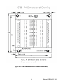
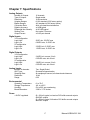
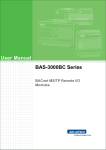
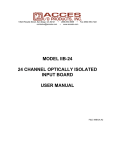
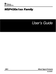
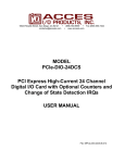
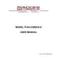
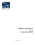
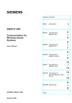
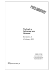
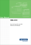
10623 Roselle Street, San Diego, CA 92121 • (858) 550-9559 • FAX (858) 550-7322 [email protected] • www.accesio.com MODEL USB-AO16-16A 16-Bit, 16-Channel Analog Output USB Module USER MANUAL FILE: MUSB-AO16-16A.C1a Notice The information in this document is provided for reference only. ACCES does not assume any liability arising out of the application or use of the information or products described herein. This document may contain or reference information and products protected by copyrights or patents and does not convey any license under the patent rights of ACCES, nor the rights of others. IBM PC, PC/XT, and PC/AT are registered trademarks of the International Business Machines Corporation. Printed in USA. Copyright by ACCES I/O Products Inc, 10623 Roselle Street, San Diego, CA 92121. All rights reserved. WARNING!! ALWAYS CONNECT AND DISCONNECT YOUR FIELD CABLING WITH THE COMPUTER POWER OFF. ALWAYS TURN COMPUTER POWER OFF BEFORE INSTALLING A CARD. CONNECTING AND DISCONNECTING CABLES, OR INSTALLING CARDS INTO A SYSTEM WITH THE COMPUTER OR FIELD POWER ON MAY CAUSE DAMAGE TO THE I/O CARD AND WILL VOID ALL WARRANTIES, IMPLIED OR EXPRESSED. 2 Manual USB-AO16-16A Warranty Prior to shipment, ACCES equipment is thoroughly inspected and tested to applicable specifications. However, should equipment failure occur, ACCES assures its customers that prompt service and support will be available. All equipment originally manufactured by ACCES which is found to be defective will be repaired or replaced subject to the following considerations. Terms and Conditions If a unit is suspected of failure, contact ACCES' Customer Service department. Be prepared to give the unit model number, serial number, and a description of the failure symptom(s). We may suggest some simple tests to confirm the failure. We will assign a Return Material Authorization (RMA) number which must appear on the outer label of the return package. All units/components should be properly packed for handling and returned with freight prepaid to the ACCES designated Service Center, and will be returned to the customer's/user's site freight prepaid and invoiced. Coverage First Three Years: Returned unit/part will be repaired and/or replaced at ACCES option with no charge for labor or parts not excluded by warranty. Warranty commences with equipment shipment. Following Years: Throughout your equipment's lifetime, ACCES stands ready to provide on-site or in-plant service at reasonable rates similar to those of other manufacturers in the industry. Equipment Not Manufactured by ACCES Equipment provided but not manufactured by ACCES is warranted and will be repaired according to the terms and conditions of the respective equipment manufacturer's warranty. General Under this Warranty, liability of ACCES is limited to replacing, repairing or issuing credit (at ACCES discretion) for any products which are proved to be defective during the warranty period. In no case is ACCES liable for consequential or special damage arriving from use or misuse of our product. The customer is responsible for all charges caused by modifications or additions to ACCES equipment not approved in writing by ACCES or, if in ACCES opinion the equipment has been subjected to abnormal use. "Abnormal use" for purposes of this warranty is defined as any use to which the equipment is exposed other than that use specified or intended as evidenced by purchase or sales representation. Other than the above, no other warranty, expressed or implied, shall apply to any and all such equipment furnished or sold by ACCES. 3 Manual USB-AO16-16A Table of Contents Chapter 1: Introduction ...................................................................................................... 5 Features ........................................................................................................................... 5 Applications ..................................................................................................................... 5 Functional Description ................................................................................................... 5 Figure 1-1: Block Diagram .......................................................................................... 6 Ordering Guide ................................................................................................................ 6 Model Options ................................................................................................................. 7 Special Order ................................................................................................................... 7 Included with your board ................................................................................................ 7 Optional Accessories...................................................................................................... 7 Chapter 2: Installation ........................................................................................................ 8 Software CD Installation ................................................................................................. 8 WIN NT/2000/XP/2003 ...................................................................................................... 8 Hardware Installation ...................................................................................................... 8 Chapter 3: Hardware Details .............................................................................................. 9 Option Selections ............................................................................................................ 9 Figure 3-1: Option Selection Map ............................................................................... 9 USB Connector ................................................................................................................ 9 Embedded USB Connector ............................................................................................ 9 DB37 Connectors .......................................................................................................... 10 LED ................................................................................................................................. 10 DC Power Jack .............................................................................................................. 10 Output Voltage Range Jumpers ................................................................................... 10 5V Resettable Fused Output ........................................................................................ 10 +5V CMOS I/O / +3.3V LVTTL I/O Configuration Jumpers .......................................... 10 Chapter 4: USB Address Information.............................................................................. 11 Table 4-1: Product ID to Model Number ................................................................... 11 Chapter 5: Programming .................................................................................................. 12 Table 5-1: Analog Output Range Codes .................................................................. 12 Sample Programs .......................................................................................................... 13 Calibration ..................................................................................................................... 13 Chapter 6: Connector Pin Assignments ......................................................................... 14 Figure 6-1: J1 DB37F Connector Pin Arrangement ................................................ 14 Table 6-1: J1 DB37F Analog Outputs Connector Pin Assignments ...................... 14 Table 6-2: J1 Signal Names and Descriptions ........................................................ 14 Figure 6-2: P4 DB37M Connector Pin Arrangement ............................................... 15 Table 6-3: P4 DB37M Digital I/O Connector Pin Assignments ............................... 15 Table 6-4: P4 Signal Names and Descriptions ........................................................ 15 Figure 6-3: STB-74 Breakout Board Dimensional Drawing .................................... 16 Chapter 7: Specifications ................................................................................................. 17 Customer Comments........................................................................................................ 18 4 Manual USB-AO16-16A Chapter 1: Introduction This multi-function USB module is an ideal solution for adding portable, easy-to-install analog outputs to any computer with a USB port. The unit is a high speed USB 2.0 device, offering the highest speed available with the USB bus. The board is plug-and-play allowing quick connection whenever you need additional I/O on a USB port. Features High-speed USB 2.0 device, USB 1.1 compatible 16-channel, 16-bit resolution digital to analog converter (DAC) outputs Jumper selectable analog output ranges of 0-10V and ±5V (contact factory for additional available ranges) Zero and span software calibration for each DAC Computer generated analog outputs up to 4 kHz simultaneously Analog outputs on female 37-pin D type connector 2 Analog inputs, 16-bit resolution, 0-5V range up to 4 kHz simultaneously 16 digital I/O lines (DIO) on male 37-pin D connector Digital I/O buffers tri-stated under program control Digital I/O buffers jumper selectable for TTL or LVTTL All 16 I/O lines pulled up for dry contact monitoring, buffered for 10mA source or 24mA sink capabilities Resettable 0.5A fused +5V available to the user Rugged steel powder coated enclosure o (except –OEM versions) Includes 115VAC to +12V regulated external power supply adapter o (except –OEM versions) Applications • Portable / Laptop • Education / Laboratory • Industrial Automation • Embedded OEM Functional Description This product features 16 digital-to-analog converters (DACs) with single-ended outputs on a female 37-pin D type connector. The board features jumper selectable unipolar and bipolar ranges for the DACs. The DACs can be updated individually or simultaneously. Each channel can be factory calibrated or to the user’s requirements through software. To ensure that there will not be excessive outputs to external circuits when the board is plugged in, automatic circuits limit analog outputs to zero volts. 5 Manual USB-AO16-16A 16 digital I/O lines are provided on a male 37-pin D type connector in two groups of 8 bits. Both digital bytes are individually configured as input or output. A two-channel 16-bit analog-to-digital converter (ADC) version of this board is also available with an input range of 0-5V per channel. The board is designed to be used in rugged industrial environments but is small enough to fit nicely onto any desk or testing station. The module is PC/104 sized (3.550 by 3.775”). Figure 1-1: Block Diagram Ordering Guide USB-AO16-16A USB-AO16-16E USB-AO16-8A USB-AO16-8E USB-AO16-4A USB-AO16-4E USB-AO12-16A USB-AO12-16E USB-AO12-8A USB-AO12-8E 16-Bit, 16-Channel Analog Output Board with 2 Analog Inputs 16-Bit, 16-Channel Analog Output Board 16-Bit, 8-Channel Analog Output Board with 2 Analog Inputs 16-Bit, 8-Channel Analog Output Board 16-Bit, 4-Channel Analog Output Board with 2 Analog Inputs 16-Bit, 4-Channel Analog Output Board 12-Bit, 16-Channel Analog Output Board with 2 Analog Inputs 12-Bit, 16-Channel Analog Output Board 12-Bit, 8-Channel Analog Output Board with 2 Analog Inputs 12-Bit, 16-Channel Analog Output Board 6 Manual USB-AO16-16A Model Options -OEM -T -10B -5V -ST DIO Pull-Downs Board only version (no enclosure or 12V external power supply) Extended Temperature Operation (-40°to +85°C) Output range of Bipolar ±10V Output range of Unipolar 0-5V Screw terminals for +12VDC power input instead of DC jack Pull-down resistors on DIO lines Special Order Contact factory at 800-326-1649 for customizations to your specific requirement. Examples of special orders would be conformal coating, vertical DB37 connectors vs. right-angle etc. Included with your board The following components are included with your shipment, depending on options ordered. Please take the time now to ensure that no items are damaged or missing. USB Module installed in Enclosure (not included with –OEM versions) 6' USB 2.0 cable Software Master CD USB I/O Quick-Start Guide 115VAC to 12VDC Regulated Power Supply (not included with –OEM versions) Optional Accessories STB-74 Kit Compact, complete breakout accessory. 74 Position Screw Terminal Board that mounts on top of the AO Module enclosure, includes short ribbon cables STB-37 37-Pin Male D connector screw terminal board. DIN-rail mountable (need 2 for complete solution) DIN-SNAP 1 foot length of snap-track with clips for mounting to DIN-rail, accepts two STB-37’s CAB37MF-36 36 inch flat ribbon cable Male to Female CAB37-36 36 inch flat ribbon cable Female to Female MP104-DIN DIN-rail mounting adapter plate for affixing any USB/104 module to a DIN-rail CUSB-EMB-6 6 foot USB Type A to micro-fit OEM header 7 Manual USB-AO16-16A Chapter 2: Installation Software CD Installation The software provided with this board is contained on one CD and must be installed onto your hard disk prior to use. To do this, perform the following steps as appropriate for your software format and operating system. Substitute the appropriate drive letter for your CDROM or disk drive where you see in the examples below. WIN NT/2000/XP/2003 a. b. c. Place the CD into your CD-ROM drive. The install program should automatically run. If it does not click START | RUN and type , click OK or press . Follow the on-screen prompts to install the software for this board. Hardware Installation The board can be installed in any USB 2.0 or USB 1.1 port. Please refer to the USB I/O Quick Start Guide which can be found on the CD, for specific, quick steps to complete the hardware and software installation. Plug in the provided AC/DC 12V regulated power supply adapter first, then plug in the USB cable. 8 Manual USB-AO16-16A Chapter 3: Hardware Details Option Selections Refer to the setup programs on the CD provided with the board. Also, refer to the Block Diagram and the Option Selection Map when reading this section of the manual. Figure 3-1: Option Selection Map USB Connector The USB connector is a Type B high-retention type connector and mates with the cable provided. The USB port provides communication signals along with +5VDC power. The board is powered externally through the DC Input Jack. The +5VDC power from the USB port is tied directly to the 5V Resettable Fused Output providing access to the user. Embedded USB Connector Micro 5-pin header in parallel with type B connector to provide a compact interface within embedded systems. (OEM version allows access to this connector) 9 Manual USB-AO16-16A DB37 Connectors Two DB37 connectors provide access to the I/O signals. Both J1 (Female, Analog signals) and P4 (Male, Digital signals) have female 4-40 UNC jack-screws. See Chapter 6 for connector pin assignments. LED The LED on the front of the enclosure is used to indicate power and data transmissions. When the LED is in an illuminated steady green state, this signifies that the board is successfully connected to the computer and has been detected and configured by the operating system. When the LED flashes continuously, this signifies that there is data being transmitted over the USB bus. DC Power Jack This is the +12 VDC input required to provide power to the board. The DC jack has a 2.00mm post on board and is designed to be used with the +12 VDC AC/DC external power supply that ships with the (non-OEM versions) board. A 2-position screw terminal block can be installed as a factory option (-ST) if the DC jack isn’t preferred. Output Voltage Range Jumpers This is used to select the range desired. See Figure 3-1 for proper position of jumpers to select either ±5V range or 0-10V range. These jumpers configure the range for all channels. 5V Resettable Fused Output A 0.5A resettable fuse feeds the digital I/O connector for general purposes. If an overcurrent persists on a circuit protected by a resettable fuse, it will open interrupting power to the circuit. The amount of time it takes the fuse to act depends on the amount of overcurrent and other conditions such as ambient temperature, humidity, etc. The fuse will remain open until the bi-metal elements cool sufficiently, at which time the circuit will be restored. +5V CMOS I/O / +3.3V LVTTL I/O Configuration Jumpers Each 8-bit digital I/O group can be configured for either 5V CMOS or 3.3V LVTTL signaling via jumper selection. 10 Manual USB-AO16-16A Chapter 4: USB Address Information Use the provided driver to access the USB board. This driver will allow you to determine how many supported USB devices are currently installed, and each device’s type. This information is returned as a Vendor ID (VID), Product ID (PID) and Device Index. The VID is “0x1605" and the PID is listed in the following table. Model Number USB-AO16-16A USB-AO16-16E USB-AO16-8A USB-AO16-8E USB-AO16-4A USB-AO16-4E USB-AO12-16A USB-AO12-16E USB-AO12-8A USB-AO12-8E Product ID “0x8070” “0x8071” “0x8074” “0x8075” “0x8076” “0x8077” “0x8078” “0x8079” “0x807C” “0x807D” Table 4-1: Product ID to Model Number The Device Index is determined by how many of the devices you have in your system, and provides a unique identifier allowing you to access a specific board. 11 Manual USB-AO16-16A Chapter 5: Programming The driver software provided with the board uses a 32-bit .dll front end compatible with any Windows programming language. Samples provided in Borland C++Builder, Borland Delphi, Microsoft Visual Basic, and Microsoft Visual C++ demonstrate the use of the driver. The following is a list of the most common function calls provided by the driver in Windows. For a complete list of available functions and details on how to use them refer to the USB Software Reference Manual located in the installation path for this board. unsigned long DACSetBoardRange(DeviceIndex,RangeCode) unsigned long DeviceIndex - number from 0-31 indicating on which device you wish to set the DAC range unsigned long RangeCode - the range code to set for the board; see the manual for your device's range codes ) Range 0-5V +/-5V 0-10V +/-10V Range Code 0 1 2 3 Table 5-1: Analog Output Range Codes unsigned long DACMultiDirect(DeviceIndex,pDACData,DACDataCount) unsigned long DeviceIndex - number from 0-31 indicating on which device you wish to set a DAC value unsigned short *pDACData - a pointer to the first of an array of WORDs, consisting of channel/value pairs; channels are from 0-7, values are from 000h-FFFh, as for DACDirect() unsigned long DACDataCount - number indicating how many channel/value pairs are in the array referenced by pDACData ) 12 Manual USB-AO16-16A Sample Programs Sample programs are useful to check out initial operation of the board as well as aiding in the understanding of the programming techniques used (sample source code provided). Calibration Each of the DACs is capable of being individually calibrated through the onboard calibration circuitry. The board is shipped from the factory already calibrated, but the user is able to calibrate each DAC to any desired preference. For example, the factory calibration is performed under benign temperature conditions, with negligible load on the DACs; the user may want to calibrate the unit at its operating temperature to improve accuracy, and / or may want to calibrate the unit and the system. The onboard calibration circuit allows both offset and scale errors to be corrected, and can provide non-linearity and other correction types, all in real-time, purely in hardware. To calibrate the board you will need to create a “calibration table” per channel. Each channel needs a file containing the corrected count values. A provided utility is then used to upload these calibration tables into the on-card circuitry, and all future readings are automatically calibrated in real-time by this circuit. These calibration tables can be created programmatically (using Y=mX+b, or more complex formulae) or even in a spreadsheet program; the most common file type is simply a single column CSV (although the API we provide will also accept raw binary files). 13 Manual USB-AO16-16A Chapter 6: Connector Pin Assignments A DB37F connector is provided for analog outputs and a DB37M is provided for the digital I/O lines. Connector pin assignments are listed below. Figure 6-1: J1 DB37F Connector Pin Arrangement Pin 1 2 3 4 5 6 7 8 9 10 11 12 13 14 15 16 17 18 19 Signal Name AGND AGND AGND AGND AGND AGND AGND AGND AGND AGND AGND AGND AGND AGND AGND AGND AGND AGND AGND Pin 20 21 22 23 24 25 26 27 28 29 30 31 32 33 34 35 36 37 Signal Name DAC0 DAC1 DAC2 DAC3 DAC4 DAC5 DAC6 DAC7 DAC8 DAC9 DAC10 DAC11 DAC12 DAC13 DAC14 DAC15 A_IN 0 A_IN 1 Table 6-1: J1 DB37F Analog Outputs Connector Pin Assignments J1 Signal Names and Descriptions AGND Analog Ground DAC0 to DAC15 Single-ended DAC output A_IN 0 to A_IN 1 0-5V Analog Input Table 6-2: J1 Signal Names and Descriptions 14 Manual USB-AO16-16A Figure 6-2: P4 DB37M Connector Pin Arrangement Pin 1 2 3 4 5 6 7 8 9 10 11 12 13 14 15 16 17 18 19 Signal Name I/O_0 GND I/O_1 GND I/O_2 GND I/O_3 GND I/O_4 GND I/O_5 GND I/O_6 GND I/O_7 GND I/O_8 GND I/O_9 Pin 20 21 22 23 24 25 26 27 28 29 30 31 32 33 34 35 36 37 Signal Name GND I/O_10 GND I/O_11 GND I/O_12 GND I/O_13 GND I/O_14 GND I/O_15 GND GND GND GND GND FUSED +5VDC Table 6-3: P4 DB37M Digital I/O Connector Pin Assignments P4 Signal Names and Descriptions GND Ground I/O_0 to I/O_15 Digital I/O FUSED +5VDC 0.5A FUSED +5VDC Output Table 6-4: P4 Signal Names and Descriptions 15 Manual USB-AO16-16A Figure 6-3: STB-74 Breakout Board Dimensional Drawing 16 Manual USB-AO16-16A Chapter 7: Specifications Analog Outputs Number of Outputs: Type of Outputs: Resolution: Unipolar Ranges: Bipolar Ranges: Conversion Rate: Relative Accuracy: Differential Non-linearity: Settling Time: Output Current: 16 channels Single-ended 16-bit resolution 0-10V standard (0-5V factory option) ±5V standard (±10V factory option) 4kHz, all channels simultaneous ±4 LSB typical ±0.25 LSB typical 8us typical, 10us max ±12 mA per channel Digital Inputs 3.3V configuration Logic High: Logic Low: 5V configuration Logic High: Logic Low: 2VDC min, 5.5VDC max 0.8VDC max, -0.5VDC min 3.5VDC min, 5.5VDC max 1.5VDC max, -0.5VDC min Digital Outputs 3.3V configuration Logic High: Logic Low: 5V configuration Logic High: Logic Low: 2.4VDC min, source 10 mA 0.55VDC max, sink 24 mA 3.8VDC min, source 10 mA 0.55VDC max, sink 24 mA Analog Inputs Number of channels: ADC Type: Sampling Rate: Resolution: Range: Two, Single-Ended Successive Approximation 4k samples per second, all channels simultaneous 16-bit 0-5V Environmental Operating Temperature: Storage Temperature: Humidity: Board Dimension: 0◦ to 70◦C -40◦ to +85◦C 5% to 95% non-condensing 3.550 x 3.775 inches Power +12VDC regulated: @ ~100 mA typical, no-load on DIO buffer sourced outputs and DAC outputs @ ~520 mA typical, full-load on DIO buffer sourced outputs and DAC outputs 17 Manual USB-AO16-16A Customer Comments If you experience any problems with this manual or just want to give us some feedback, please email us at: [email protected]. Please detail any errors you find, we will reply with manual updates. 10623 Roselle Street, San Diego CA 92121 Tel. (858)550-9559 FAX (858)550-7322 www.accesio.com 18 Manual USB-AO16-16A