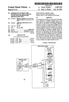
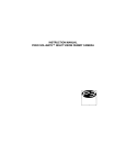
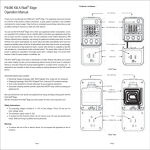
1
Kill A Watt
Wireless
with
Carbon Footprint Meter
P4225 and P4220
Kill A Watt
sans fil
avec
capteur d'empreinte au carbone
P4225 et P4220
Please read these operating instructions carefully before
using the product, and keep the instructions in a safe place
for reference. If you allow third parties to use this product,
make sure you pass on the operating instructions.
1.
1.1.
Introduction
Intended use
2.
Scope of delivery
5
3.
Terminology
5
4.
Features and functions
4.1.
General
4.2. Wireless sensor unit
4.3. Wireless Sensor Display Panel
2
4
4
6
6
6
6
5.
Safety instructions
7
6.
Battery and environmental instructions
8
7.
7.1.
7.2.
Preparation for operation, commissioning
Commissioning the wireless sensor display panel
Starting up the sensors
8
8
8
8.
Display and control elements
8.1.
Display of the wireless sensor display panel
8.2. Control elements
9
9
10
9.
Operation
9.1.
The key I"
9.1.1. Short press of the button:
Displaying the costs for various time periods
9.1.2. Long press of the button:
Price per kWh and the CO2 equivalent
9.2. The key "Data"
9.2.1. Short press of the button:
Measurement value display for the sensors
9.2.2. Long press of the button:
Resets the measurement values for the respective sensor
9.3. The sensor button
9.3.1. Short press of the button: Changing displayed sensor
9.3.2. Long press of the button: Teaching and resetting sensors
9.4. What is displayed when
11
11
11
13
14
14
14
14
14
15
16
10.
Changing batteries of the wireless sensor display panel
11.
Troubleshooting
18
19
12.
Range
20
13.
Maintenance and cleaning
21
14.
Handling
22
15.
Disposal
22
16.
Technical specifications
16.1. Wireless sensor display panel
16.2. Wireless sensor unit
23
23
23
17.
FCC Information
17.1. FCC Information Wireless sensor display panel
17.2. FCC Information Wireless sensor unit
24
24
25
18.
26
Service and warranty information
3
1. Introduction
Dear Customer,
Thank you for purchasing this product.
The product has been EMC-tested and meets the current national
requirements. See also FCC-Information.
Please observe these operating instructions in order to maintain this
condition and ensure safe operations.
Prior to using the product for the first time, please read the entire operating
manual and observe all operating and safety instructions.
cOr= Please note the correct order for commissioning the product.
Please also observe the mounting instructions and the information
on radio interference between the sensors and base station.
All company names and product descriptions listed herein are the
trademarks of the respective manufacturers. All rights are reserved.
1.1. Intended use
Kill a Watt is an energy measurement system consisting of a wireless
sensor display panel and up to eight energy sensors. The energy sensors
send their measurement values via radio signal to the wireless sensor
display panel.
The energy measurement system is only to be operated in dry interior
rooms.
Manufacturer assumes no responsibility for incorrectly displayed or
measured values, and/or any consequences ensuing from them.
The product is intended for private use only. It is not designed for medical,
commercial or public safety purposes.
The components of this product are not toys. Do not allow children to
operate them.
The wireless sensor display panel is battery-operated.
A
4
Any other use than that described above may lead to damage
to the product or to other danger.
Please read these operating instructions carefully for important information on deploying, using, and operating the product.
2. Scope of delivery
•
•
•
•
Wireless sensor display panel
Plastic base for display panel
Wireless sensor unit
Operating instructions
3. Terminology
An exclamation mark in a triangle indicates important instructions in the operating manual which must be observed under
all circumstances.
A
co=
The "hand" icon points to special tips and instructions on using
the product.
5
4. Features and functions
4.1. General
Kill a watt wireless allows the user a simple cost check and a resulting
cost prediction. Technical measuring data (instantaneous power, current,
consumed energy) is shown here, but it is in the background compared
with cost, which is made clear by permanently showing the cost/predicted
cost and the highlighted button (with $ sign).
The system consists of two types of devices:
• Display unit with display and control elements
(data presentation)
• Wireless sensor unit realized as socket adapter
The device can be installed without any tools and is easy to operate.
Up to 8 wireless sensor units can be assigned to each display unit.
Values are transmitted from the wireless sensor unit to the display unit
via radio signal.
4.2. Wireless sensor unit
All physical values for cost calculation are determined in the wireless
sensor unit:
• Current
• Voltage
• Phase angle
• Effective power
• Power consumption since previous data transmission
• Accumulated power consumption
Data is transmitted cyclically.
The wireless sensor unit is already taught to the wireless sensor display
panel when the system is delivered as set.
4.3. Wireless sensor display panel
The transmitted measurement values are shown on the wireless sensor
display panel. The displayed energy costs are determined from the price
for one kWh. You can enter the price per kWh by yourself. A default value
has been defined for delivery.
The displayed CO2 emissions are calculated from the emission equivalent
for one kilowatt hour.
6
5. Safety instructions
A
•
•
•
•
•
•
•
We shall not assume any liability for damage to items or
persons caused by improper handling or non-observance of
the safety instructions!
In such cases, any guarantee claims shall become null and
void.
Do not use this product in hospitals or medical institutions. Although
the sensors only emit relatively weak radio signals, these may cause
interference to life-support systems. The same can also apply in other
areas.
Do not use the unit, if there is damage to the housing.
Do not subject the device to temperatures below 32°F (0°C) or above
158°F (70°C).
For safety and licensing reasons (FCC), it is not permitted to convert
or modify the product.
Do not leave the packaging material laying around. Plastic foil and
bags, polystyrene parts etc. are dangerous in the hands of children.
This product is not a toy. It contains glass and small parts. Children
can be injured by swallowing them. Use the unit out of the reach of
children.
This product is not a toy for pets. It contains glass and small parts.
Pets can be harmed if they play with the unit.
7
6. Battery and environment instructions
•
Batteries do not belong in the hands of children.
•
Observe the correct polarity when inserting the batteries/rechargeable
batteries.
•
Do not leave batteries lying around, as pets or small children might
swallow them. If your child or pet swallows a battery, consult your
doctor or vet immediately.
•
Leaking or damaged batteries/rechargeable batteries may lead to
injury to the skin. For this reason, use suitable protective gloves when
changing them.
•
Make sure that batteries or rechargeable batteries are not thrown into
the fire or short-circuited. Risk of explosion!
•
Never dismantle batteries/rechargeable batteries!
•
•
Do not recharge normal batteries. Risk of explosion!
If you will not be using the product for an extended period of time (e.g.
for storage), please remove the inserted batteries/rechargeable batteries
in order to prevent damage caused by leaking batteries/rechargeable
batteries.
7. Peparation for operation, commissioning
7.1. Commissioning the wireless sensor display panel
•
•
•
•
Open the battery compartment at the back of the wireless sensor display
panel.
Insert three batteries (AA cells) into the battery compartment observing
correct polarity. Use alkaline batteries if possible.
Although you can use rechargeable batteries, this will reduce the
operational life due to their lower voltage / capacity.
Close battery compartment.
After you have inserted the batteries, all LC-display segments are
actuated briefly, after which the version number is displayed.
7.2. Starting up the sensors
The energy sensors are integrated in socket adapters. Insert the sensor in
the socket outlet to which the device you want to meter is connected. Plug
the power cable of the device that you want to monitor into the receptacle
of the energy monitor. The sensor included in the set is already taught upon
delivery. To teach in other sensors, proceed as described in 9.3..
8
8. Display and control elements
8.1.
Display of the wireless sensor display panel
Forecast period
Sensor address
Forecast. Day VOA Month Year!
Sensor: 1 2 3 4 5 6 7 8 ,,,,,
4i1
1 1 1 1 1 1 1,1
Energy costs /CO,
emission
Reception status /
progress indicator
Low battery warning
0 0.0.0 u LT111
RAM
Metered
values
no nnr 0.0 0 Rt."
0 u.0 0 4 u u.0
Elapsed time
Legend for Symbols
Forecast Period
Time periods for the displayed forecast value
Sensor address
Sensor address for the data shown on
the display
Energy costs / CO, emission
Energy costs in $ or CO 2 emission in
Lbs.
Metered Values
Physical measurement data: Used
energy, current, voltage, power factor
Reception status / progress
indicator
Progress indicator, time between two
measurement value transmissions
Low battery warning
Symbol is shown as a warning for a
low battery
Elapsed time
Elapsed time since the beginning of
the metering
9
8.2. Control elements
Key $
Key Sensor
Key Data
Three operational buttons are provided on the device. They are allocated
with two functions selected with a short/long press of the button.
The two buttons on the right can also be used as value input buttons
depending on the context.
The respective buttons can be pressed shortly to recall certain values
and can be used for configuration with long press.
10
Key "$"
Cost forecast for various time periods
Key "Data"
Measurement value button / +, Display of
measurement values for a sensor
Key "Sensor"
Sensor button / -, changes the display between
individual sensors, switches Auto-function on
9. Operation
The wireless sensor display panel is an 8 in 1 status display for up to 8 energy sensors. Besides the total costs and the total power consumption for
all sensors, there are no other sensor-encompassing values.
[0.= Short and long pressing of the button selects
different functions.
•
Short: < 3 s
•
Long: > 3 s
9.1. The key $
9.1.1. Short press of the button:
Displaying the costs for various time periods
A short press of the button switches between the costs for different time
periods. This is shown in detail in the following diagram. Basically all other
buttons function in the same way.
11
25 uu
nn $
12E3- IsErf
The measurement values are shown one after the other:
• Total costs for the displayed sensor or for all sensors together
(the display shows $ or Lbs. above the text "Total")
• Forecasted costs for the day
• Forecasted costs for the week
• Forecasted costs for the month
• Forecasted costs for the year
12
9.1.2. Long press of button:
Price per kWh and the CO2 equivalent
A long press of the $-key takes you to the setup mode for the price per
kWh (in ct). Default value is 10 ct/kWh. The display flashes and no unit is
shown. All other segments are turned off.
The entry is made with keys "Data/+" and "Sensor/-" (buttons 2 and 3).
Confirm the entry with the "$" button.
Now enter the respective CO2 equivalent (lbs/kWh). A default value is defined here as well (1.669 lbs/kWh). Confirm the entry with the "$" button.
Finally, define the value that is to be permanently displayed on the large
display: Costs (display shows dEF $) or CO2 emission (display shows
dEF Lbs).
P
Exit setup mode by pressing the $ key again. If no entry is made for 20s,
setup mode is aborted automatically.
13
9.2. The key "Data"
9.2.1. Short press of the button: Displaying metered values
A brief press of this button shows the various measurement values in
sequence, in the lower left-hand area for the current sensor:
•
•
•
•
•
Total power consumption in kWh (as with an electricity meter)
Current power consumption (effective power)
Actual current
Actual voltage
Power factor (cos cp)
For the total display for all sensors together, only the total power consumption is displayed in kWh or MWh.
9.2.2. Long press of button: Resetting the measurement values for the
respective sensor
In order to delete metered data and to reset the measurement time, set
the wireless sensor display panel to delete mode. This is done by pressing the "Data" button for longer than three seconds.
The display shows the number of the sensor for which the data is to be
deleted. The area for displaying the measurement values shows a flashing "----" and all symbols for dimensional units.
Pressing the button for another extended period then closes the deletion
function and the display returns back to normal mode.
You can abort delete mode by pressing any key briefly.
If no entry is made for 20s, delete mode is aborted automatically.
All accumulated values are deleted! The display for the elapsed
measuring time for the respective sensor is reset.
9.3.
The "Sensor" button
9.3.1. Short press of the button: Changing displayed sensor
Use this button to switch the display between the various added sensors
(1-8 if available). The display unit always refers to the displayed sensor.
After you have gone through all individual sensors, the sum of all sensors
is shown. No sensor number is shown on the display!
14
For the total display, the total consumption for the measurement data in
kWh or MWh is displayed is the lower left.
If more than one sensor has been assigned (trained), you can put the wireless sensor display panel into automatic mode. This is done by pressing
on the "Sensor" button until all the display has completed for all sensors
and the total display and the text "Auto" appears on the display.
9.3.2. Long press of button: Teaching and deleting sensors
Teaching
In order to add another sensor, put the wireless sensor display panel into
"Teach mode". This is done by pressing the "Sensor" button for longer
than three seconds.
The display is clear except for a flashing! "L" in the large seven-segment
display.
If a new sensor is now inserted into the socket, it is added to the next
free position.
The large seven-segment display shows the memory location for the new
sensor (e.g. location 3) for 5 seconds, teach mode is ended and normal
mode appears on the display.
If no more memory locations are free, the large seven-segment display
shows . In order to add a new sensor, an old one must be deleted
in this case.
You can abort teach mode by pressing any key shortly. If no key press is
made for 20s, teach mode is aborted automatically.
Deleting
Call up the display for the sensor to be deleted with the sensor key. Start
teach mode as described above. The display is blank except for a flashing "L".
Press the sensor key for longer than three seconds again. The number of
the sensor to be deleted appears on the large display (e.g.: 2).
Confirm the sensor to be deleted with the displayed number by means
of a long button press.
All data belonging to the respective sensor is lost! (The measurement
times in all accumulated measurement values are reset for this sensor
memory location).
If all sensors are deleted, only lines are shown in all seven-segment displays on all displays.
You can abort teach/delete mode by pressing any key shortly. If no key
press is made for 20s, teach/delete mode is aborted automatically.
15
9.4. What is displayed when...
What is displayed in the section "Metered values" when Sensor 1-8 or
auto function is selected:
Pressing Key
Data
Pressing
Key "$"
Total
Forecast for a
day
Forecast for a
week
Forecast for a
month
Forecast for a
year
Total
cumulated
power
consumption
of selected
Sensor
Estimated
power
consumption
of selected
Sensor for the
day
Estimated
power
consumption
of selected
Sensor for the
week
Estimated
power
consumption
of selected
Sensor for the
month
Estimated
power
consumption
of selected
Sensor for the
year
one time
two times
three times
four times
Actual power
consumption
Actual current
consumption
Actual voltage
Actual power
factor
c0= When auto function is activated the display content automatically changes and metering data for each sensor successively is
displayed When pressing the data key once actual power consumption of the respective sensor is displayed and so on. At the
time when the display shows actual metering data the writing
"Forecast" vanishes.
Pressing the "$" key always causes a return to the top of column
one and the respective power consumption is displayed.
16
What is displayed in the section "Metered values" when the sum over all
sensors is selected:
Press Key
Data
Press
Key "S"
Total
Forecast for a
day
Forecast for a
week
Forecast for a
month
Forecast for a
year
Pressing the "Data" key takes no effect
Total cumulated power consumption of all Sensors.
Estimated power consumption of all Sensors for the day
Estimated power consumption of all Sensors for the week
Estimated power consumption of all Sensors for the month
Estimated power consumption of all Sensors for the year
Example:
Sensor 3 is chosen and in section "Metered values" the actual current
consumption is displayed.
When changing to "all sensors" (no sensor number is shown in the display = sum of all sensors) by pressing the key "Sensor" a value for the
cumulated or estimated power consumption of all sensors is displayed.
What is displayed in the section "Elapsed time" depending on the selected sensor:
Selected Sensor
Sensor 1 — 8 or Auto function is selected
Sum over all sensors
Displayed value in the section "Elapsed time"
The elapsed time since starting the measurement
of the respective sensor
nothin
c0== Pressing the key "$" takes no effect on the values displayed in
section "Elapsed time".
17
10. Changing batteries of the wireless sensor display panel
c0=, Depending on what type of batteries or rechargeable batteries
you use, the replacement interval can be very different.
Highquality alkaline batteries provide longest service, rechargeable batteries or cheap zinc-carbon batteries require more frequent changing.
If the battery flat symbol appears in the display (4=a ), your batteries need
replacing.
•
•
•
•
•
•
Always replace the whole set of batteries.
Never mix new batteries with "used" batteries.
Always use three batteries of the same type by the same manufacturer.
Do not mix batteries with rechargeable batteries.
As already mentioned, you can use rechargeable batteries, however, durability is appreciably lower than with batteries.
Follow the instructions in chapter 7.1 to change the batteries.
r2r=. Please observe the following:
After replacing the batteries, all data, values stored in the wireless
sensor display panel are deleted and must be entered again.
18
It Troubleshooting
A
Observe the safety Instructions contained in these operation
instructions!
Problem
Remedy
No reception
•
•
•
•
•
•
•
The distance between the wireless sensor display
panel and sensors is too great. Relocate the sensors.
Objects or shielding materials are interfering with
the radio reception. Relocate the sensors and the
wireless sensor display panel.
Another transmitter on the same or a neighboring
frequency is interfering with the radio signal from
the sensors.
If possible, set other devices to a different frequency
The wireless sensor unit is not inserted into the
socket
The socket inserted in the wireless sensor unit
has no voltage applied
Power failure, the sensor is not being supplied
with power
19
12. Range
The transmission range of the radio signals to the wireless sensor display
panel is 300 ft. under optimum conditions. This is often described as the
"free field range".
c0= This ideal arrangement (e.g. wireless sensor display panel and
wireless sensor unit on a smooth, level field without trees, houses
etc.) is, however, never found in practical conditions.
You, will normally wish to set up the wireless sensor display panel in your
home, with the sensor and additional sensors somewhere else in your
home.
The following can considerably reduce the reception range:
•
walls, reinforced steel ceilings
•
coated/layered insulation glass panes
•
vehicles
•
trees, bushes, earth, rocks
•
proximity to metal & conductive objects (e.g. radiators)
•
proximity to the human body
•
broadband disturbances, e.g. in residential area (Cordless telephones, mobile phones, radio headphones, radio loudspeakers,
radio weather stations, baby monitors etc.)
•
proximity to electric motors, transformers, switching power supplies or computers
•
proximity to poorly shielded computers with open panels or other
electrical devices
c0c= As the local circumstances are different at every location, we
cannot guarantee a specific reception range. If your wireless
sensor display panel is not receiving data from the sensor reduce the distance between the sensors and the wireless sensor
display panel, and relocate the devices.
20
13. Maintenance and cleaning
13.1. General
Check the technical safety of the product regularly, e.g. damage to the
housing.
If it can be assumed that the device is not safe for operations, switch
the device off, and secure against inadvertent switching on. Remove the
batteries.
You can assume that the device is not fit for use if
•
the device shows visible damage
•
the device is no longer functional
•
after extended periods of storage in unfavorable conditions
•
after transportation in unfavorable conditions
Observe the following safety instructions before cleaning or servicing the
device:
A
Remove the batteries before cleaning, servicing or repair work.
There are no user-serviceable parts on the inside; do not open
the device. Repairs may only be carried out by a specialist who
is familiar with the associated hazards and relevant regulations
applying to the device.
13.2. Cleaning
Dust can be removed very easily with a vacuum cleaner and a soft, clean
brush. Hold the vacuum cleaner nozzle close to the device (avoid touching the device as this may cause scratching!) and remove the dust with
the brush. The dispersed dust will be sucked in by the vacuum cleaner.
Use a soft, dry, lint-free cloth to clean the exterior of the product. In case
of heavy soiling, you can use a cloth slightly moistened with warm water.
Never use aggressive cleaners or chemical solutions as this could damage the surface of the device or impair its functionality.
21
14. Handling
Observe the safety precautions in these operation
instructions!
Never open or dismantle the product (except for the tasks described in
these operating instructions, e.g. changing the batteries). There are no
user-serviceable parts inside the product.
Dropping the product will cause damage, even from a low height.
Avoid the following adverse ambient conditions during operation or
transport:
• moisture or excessive humidity
• extreme cold or heat
• direct sunlight
• dust or flammable gases, vapors or solvents
• heavy vibration
• strong magnetic fields, such as, for example, in the vicinity of machines or speakers
Never use the product immediately if it has been taken from a cold area
to a warm area. This causes condensation which could destroy the device under certain circumstances.
Wait until the devices have reached room temperature. This can take
several hours!
Choose a safe and stable location for the wireless sensor display panel,
and ensure that the wireless sensor display panel cannot fall down - danger of injury.
Valuable or easily scratched furniture surfaces should be protected from
damage by suitable mats before setting up the wireless sensor display
panel.
15. Disposal
15.1. General
Dispose of the unusable product according to valid legal regulations.
15.2. Disposing of batteries/rechargeable batteries
Dispose of exhausted batteries properly.
22
16. Technical specifications
16.1. Wireless sensor display panel
Voltage supply:
Battery:
Data transmission:
Radio frequency:
Modulation type:
Ambient temperature:
Relative humidity:
Altitude:
IP degree of protection:
Display (viewing area) (H x W):
Dimensions (H x W x D):
With stand:
Without stand:
Approval:
FCC:
3 x 1.5 V LR6 / Mignon / AA-cells
916.5 MHz
AM, 100 % (00K)
0°C to 50°C (32°F to 122°F)
max. 80 % rel. H. @ 30°C
max. 2000 m
IP 20 - Indoor use
40.5 mm x 56 mm
1.6 inch x 2.2 inch
145 mm x 104 mm x 55 mm
4.1 inch 5.7 inch x 2.2 inch
128 mm x 104 mm x 33 mm
4.1 inch x 5 inch x 1.3 inch
FCC Part 15, Subpart B
16.2. Wireless sensor unit
Operating voltage:
Max. operating voltage:
Load current:
Max. connection load:
Measurement category:
Pollution degree:
Data transmission:
Transmission frequency:
Modulation type:
Transmission power sent:
Ambient temperature:
Relative humidity:
Altitude:
Connections:
IP degree of protection:
Dimensions (1N x H x D):
Approval:
FCC:
Safety:
115 V / 60 Hz
125 V / 60 Hz
max. 15 A
1875 VA
CAT II
2
916.5 MHz
AM, 100 % (00K)
max. 93.9 dBpV/m 3 m
0°C to 50°C (32°F to 122°F)
max. 80 % rel. H. @ 30°C
max. 2000 m
NEMA 5-15
(2 pole, 3 wire, grounding type)
IP 20 - Indoor use
56 mm x 134 mm x 61 mm
(2.2 inch x 5.3 inch x 2.4 inch)
FCC Part 15, Subpart C,
Section § 15.249
UL 61010-1 Second Edition,
CAN/CSA C22.2 No. 61010-1
Second Edition
23
17. FCC information
17.1. FCC Information Wireless sensor display panel
Changes or modifications not expressly approved in writing by P3 International may
void the users authority to operate the equipment.
DoC Statement
This device, trade name P3, model number ECC100D-US, complies with Part 15
of the FCC Rules.
Operation is subject to the following two conditions:
(1)
(2)
this device may not cause harmful interference, and
this device must accept any interference received, including interference that
may cause undesired operation.
The responsible party for this device compliance is:
P3 INTERNATIONAL CORPORATION
132 Nassau Street
New York, NY 10038, USA
Phone: +1 (212) 346 79 79
24
17.2. FCC Information Wireless sensor unit
FCC ID: RNT-ECC100S-US
Changes or modifications not expressly approved in writing P3 International may
void the user's authority to operate the equipment.
NOTE: This equipment has been tested and found to comply with the
limits for a Class B digital device, pursuant to Part 15 of the FCC Rules.
These limits are designed to provide reasonable protection against harmful
interference in a residential installation. This equipment generates, uses and can
radiate radio frequency energy and, if not installed and used in accordance with the
instructions, may cause harmful interference to radio communications. However,
there is no guarantee that interference will not occur in a particular installation. If this
equipment does cause harmful interference to radio or television reception, which
can be determined by turning the equipment off and on, the user is encouraged to try
to correct the interference by one or more of the following measures:
•
•
•
•
Reorient or relocate the receiving antenna.
Increase the separation between the equipment and receiver.
Connect the equipment into an outlet on a circuit different from that to which the
receiver is connected.
Consult the dealer or an experienced radio/TV technician for help.
The internal antenna used for this mobile transmitter must provide a
separation distance of at least 20 cm from all persons and must not
be co-located or operating in conjunction with any other antenna or
transmitter.
This device, complies with Part 15 of the FCC Rules. Operation is subject to the
following two conditions:
(1)
(2)
this device may not cause harmful interference, and
this device must accept any interference received, including interference that
may cause undesired operation.
25
18. Service and Warranty information
P3 INTERNATIONAL CORPORATION LIMITED WARRANTY
P3 INTERNATIONAL CORPORATION (P3) warrants to the original retail
purchaser only, that its product is free from defects in material or workmanship under the condition of normal use and service for a period of six
(6) months from the date of purchase. In the event that a defect, malfunction or failure occurs or is discovered during the warranty period, P3 will
repair or replace at its option the product or component part(s) which
shall appear in the reasonable judgment of P3 to be defective or not to
factory specifications.
A product requiring service is to be returned to P3 along with the sales
receipt or other proof of purchase acceptable to P3 and a statement describing the defect or malfunction. All transportation costs shall be borne
by the owner and the risk of loss shall be upon the party initiating the
transportation. All items repaired or replaced thereunder shall be subjected to the same limited warranty for a period of six (6) months from the
day P3 ships the repaired or replaced product.
The warranty does not apply to any product that has been subject to
misuse, tampering, neglect, or accident or as a result of unauthorized
alterations or repairs to the product. This warranty is void if the serial
number (if any) has been removed, altered, or defaced.
This warranty is in lieu of all warranties expressed or implied, including
the implied warranties of merchantability and fitness for a particular purpose which are expressly excluded or disclaimed. P3 shall not be responsible for consequential, incidental or other damages, and P3 expressly
excludes and disclaims liability for any damages resulting from the use,
operation, improper application, malfunction or defeat of any P3 product
covered by this limited warranty.
P3's obligation is strictly and exclusively limited to the replacement or
repair of any defective product or component part(s). Some states do
not allow the exclusion or limitation of incidental or consequential damages, so the above limitation or exclusion may not apply to you. P3 does
not assume or authorize anyone to assume for it any other obligation
whatsoever. Some states do not allow limitation on how long an implied
warranty lasts, so the above limitations may not apply to you. It is the
owner/user's responsibility to comply with local, state, or federal regulations, if any, that may pertain to P3 products or their use. This warranty
gives you specific legal rights, and you may also have other rights which
vary from state to state.
26
If you experience difficulty in the operation of your unit, or if your unit
requires repair please contact:
P3 INTERNATIONAL CORPORATION
TECHNICAL SUPPORT
132 Nassau Street
New York, NY 10038, USA
Tel: 212-741-7289
Fax: 212-741-2288
Email: [email protected]
27
P4200 Kill A Watt® Wireless Addendum
Learning your Power Profile and setting the CO2 equivalent value
Background:
The electricity we consume comes from many different sources. It can be generated from
fossil fuels such as Oil, Natural Gas and Coal. These methods often emit air pollutants into
the atmosphere. Some of these emissions have been referred to as "greenhouse gases".
Other sources of electricity such as Nuclear, Hydro, Wind and Solar may have other
impacts on our environment but do not typically emit these gases.
There are many gases produced in the consumption of fossil fuels. Typically, Carbon
Dioxide (CO2) is the most common. We will refer to CO2 emissions in the use of this
product. However, other pollutants are considered in your local Power Profile and in the
estimate displayed by the product.
The Kill A Watt Wireless product will allow you to estimate the quantity of these pollutants
that are discharged into the atmosphere in the production of the electricity that you
consume. In order to more accurately estimate this value, you can change the factory-set
CO2 equivalent that is already set in your unit.
Finding your local "Power Profile":
To provide you the most accurate estimate of emissions produced in the generation of
your electricity, you must learn the profile of your local electric utility. What sources of fuel
do they use and how many Pounds of emissions are produced per Kilowatt-Hour* of
electricity generated? Most electric utilities publish this information and it can be found in
reference material or from the customer service department. Use one of these methods to
determine the rate for your utility and set it into the unit as per the operating instructions.
Methods:
1.
From your utility: Call, write or email the customer service department for your electric
utility. Their contact information is usually printed on your electric bill and their
website. You could also contact the Public Utility Commission for your State, Province
or district. Ask them for their emission rate in pounds per kilowatt-hour (lbs/kWh).
2.
From the Internet: There are online resources for this information. In the USA, the
Federal Environmental Protection Agency publishes this information and it is available
on their website http://www.epa.gov . Search their site for "Power Profiler". Currently
this information is located at the URL http://www.epa.gov/cleanenergy/energy-andyou/how-clean.html . This location may change as the site is updated. This site as well
as other sites will allow you to enter your location information and receive a report
which will contain your local emission rates in pounds per kilowatt-hour (lbs/kWh).
Similar information is available from Environment Canada for electric utilities located
in Canada. The web site is http://wvvw.ec.qc.ca . Search for Electricity Intensity Tables.
* The Kill A Watt Wireless uses a CO2 equivalent factor in pounds per kilowatt-hour
(lbs/kWh). Data you find from your utility may be expressed in other terms such as tons per
gigawatt-hour etc. If so, you must convert this factor to lbs/kWh for proper function.
Add. 0610