1
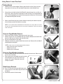
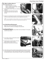
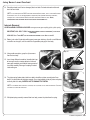
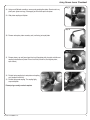
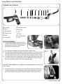
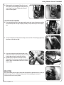
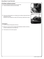
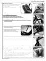
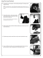
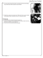
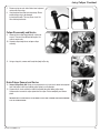
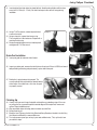
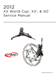
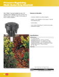
2006
Juicy Disc Brake
Technical Manual
®
English
95.5311.575.000 Rev. A
© SRAM Corporation, 2005
2006
Juicy Disc Brake
Technical Manual
®
English
The Juicy Technical Manual was created to help you tune, service and troubleshoot your
Avid product. For exploded diagrams and part number information, refer to the Avid Spare
Parts Catalog available on our website at www.avidbike.com or www.sram.com. Contact
your local
distributor or visit our website for ordering information.
NOTE: Information contained in this publication is subject to change at any time without
prior notice. For the latest technical information, visit our website.
Names used in this publication may be trademarks or registered trademarks of others.
95.5311.575.000 Rev. A
3
Juicy Seven Lever Overhaul
Juicy Seven
Lever
Overhaul
®
Tools/Kits
• Avid Juicy Bleed Kit
• 1/4” socket wrench
• 2.5mm hex wrench
• Sharp pick
• T-10 Torx wrench
• Needle-nose pliers
• E-clip tool (optional)
• Small and large flathead screwdrivers
• Safety glasses
• Clean rags
• Soapy water
Why does the brake lever assembly need to be serviced?
If brake fluid is leaking from any area of the brake lever assembly, there may be damage or wear-n-tear to internal moving parts. Inspection
and/or replacement of all damaged or worn parts will improve brake function.
If your brake was filled with brake fluid OTHER than DOT 4 or 5.1, damage to all rubber and plastic internal parts may exist. Inspection
and/or replacement of these parts will improve brake function.
If your brake was damaged in a crash, there may be damage to the lever blade and pushrod assemblies, as well as the reservoir cap,
bladder and star wheel assemblies. Inspection and/or replacement of these parts will improve brake function.
95.5311.575.000 Rev. A
5
Juicy Seven Lever Overhaul
Getting Started
Step 2
1. Remove brake lever from handlebar. Remove caliper from fork or frame. If dirty, clean with
soapy water and a clean rag. Pull hose boot off compression nut and slide down hose.
2. Using an 8mm crow’s-foot (included in Avid Bleed Kit) and socket wrench (or use a flare nut
8mm wrench), loosen and remove compression nut from lever body. Turn counterclockwise to
remove. Unthread completely by hand and slide compression nut down hose. Pull brake hose
and compression fitting from lever body.
3. Allow any brake fluid to drain into a container. Hold lever assembly over container and pump
lever to remove any brake fluid inside lever assembly.
Step 3
NOTE: IF THE SYSTEM HAS BEEN CONTAMINATED WITH THE WRONG FLUID, YOU WILL NEED TO FLUSH ALL
THE PARTS WITH SOAPY WATER AND ALLOW TO DRY FULLY PRIOR TO REBUILDING. YOU WILL ALSO NEED TO
INSTALL A NEW HOSE.
Reservoir Cover/Bladder Removal
4. Using a small Phillips screwdriver, remove both reservoir cover screws.
5. Remove reservoir cover cap and bladder from lever assembly. Additional brake fluid will drain
from lever. Hold lever over container and allow fluid to drain.
6. Set lever assembly down on clean towel.
7. Holding the reservoir cover, remove bladder from reservoir cover. Replace with new bladder if
contaminated and leaking fluid.
Step 4
NOTE: POSSIBLE CAUSES OF LEAKING BLADDER AND/OR RESERVOIR:
• Brake system may have too much fluid
• Bladder may have split
• Bladder may be contaminated
Step 8
Reservoir Cover/Bladder Installation
8. Insert new bladder into cover and seat flush into underside of reservoir cover. Make sure you
have the correct orientation.
9. Place reservoir cover and bladder back onto lever body.
Install and tighten cover cap screws (short screw
closest to lever clamp). Tighten both screws with
a Phillips screwdriver.
Bleed Screws Removal
Step 10
Step 11
10. Use a T-10 Torx wrench to remove both bleed screws.
11. Using a sharp pick, remove both o-rings on bleed screws
and replace.
12. Install bleed screws back into lever body.
6
© SRAM Corporation, 2005
Juicy Seven Lever Overhaul
Star Wheel and Worm Removal:
(Worm is attached to star wheel)
• Replace IF: damaged, cracked broken.
• Replace IF: switching sides of lever body or rotating
brake lever to other side of bar.
13. Remove retaining e-clip with sharp pick or small flathead
screwdriver.
14. Unthread star wheel and worm from lever body.
Unthread by hand; pull out to remove from lever
assembly.
Step 13
Step 14
Step 15
15. Using a pick, insert into gear hole, and push star wheel bushing out of lever body. Set star
wheel/ worm assembly aside and continue on to lever blade/pushrod replacement.
NOTE: IF YOU ARE PERFORMING A COMPLETE OVERHAUL, DO NOT INSTALL STAR WHEEL AND WORM GEAR
BACK INTO LEVER ASSEMBLY AT THIS POINT. SKIP TO LEVER/PUSHROD REPLACEMENT STEP.
Lever Blade/Pushrod Replacement
•
•
Replace lever IF: lever is bent or damaged (crash replacement).
Replace pushrod IF: pushrod is bent or damaged (crash replacement).
Step 16
Lever/Pushrod Removal
16. Holding the lever in both hands, place your thumbs near the pivot and push. The lever gently
snaps into the open position.
17. Use a 2.5mm hex wrench and unthread lever pivot set
screw and remove completely.
Step 17
Step 18
18. Using a sharp pick, or small hex wrench, push lever
pivot pin through lever body and remove.
19. Slide pivot pin out and remove lever from body.
Step 20
20. Pull lever blade away from lever body and remove pushrod pin from worm gear. It will pop out.
21. Remove pushrod from lever. Replace pushrod dust boot if damaged. Clean if not damaged.
Insert pushrod dust boot back onto pushrod (open end facing pin; closed end toward threads).
95.5311.575.000 Rev. A
7
Juicy Seven Lever Overhaul
22. Reinstall pushrod (new if bent or damaged) into lever blade. Pushrod unthreads and threads
back into lever blade.
Step 22
NOTE: IF YOU ARE REPLACING ONLY THE LEVER BLADE AND/OR PUSHROD, SKIP TO THE LEVER/PUSHROD
INSTALLATION STEPS. IF YOU ARE PERFORMING A COMPLETE LEVER ASSEMBLY INTERNALS OVERHAUL,
CONTINUE ON TO THE FOLLOWING ‘GEAR/COUPLING/PISTON/SPRING’ REMOVAL STEPS. AGAIN,
LEVER/PUSHROD AND STAR WHEEL INSTALLATION SHOULD BE PERFORMED LAST.
Internals Removal
LEVER ASSEMBLY INTERNALS INCLUDE: worm gear, worm gear coupling, piston, piston spring.
Step 23
IMPORTANT, 2006 JUICY 7 ONLY: WORM GEAR RETAINING CLIP MUST BE REMOVED (C-CLIP ABOVE
WORM GEAR).
2004-2005 JUICY 7 DOES NOT USE THE WORM GEAR RETAINING C-CLIP. SKIP TO STEP 26.
23. Rotate (push end of clip to rotate within groove) worm gear retaining c-clip with a small flathead
screwdriver or sharp pick, until the end of the clip protrudes past gap in lever body.
Step 24
Step 25
24. Using needle-nose pliers, grasp the clip to remove
from the lever body.
25. Insert a large flathead screwdriver into wide slot in top
of worm gear and turn counterclockwise. Unthread
worm gear completely and slide/pull worm gear out of
lever body assembly. Worm gear coupling is located
inside worm gear.
Step 26
26. The piston spring (below piston inside lever body) should force piston assembly out of lever
body. If the spring does not aid piston removal, use a sharp hooked pick to pull piston and spring
assembly from lever body. CAREFUL NOT TO DAMAGE THE PISTON.
NOTE: IF THE WORM GEAR COUPLING IS CRACKED, PULL COUPLING OUT OF GEAR AND REPLACE. COUPLING
CAN WEAR OUT OVER TIME AND CRACK.
Step 27
27. With piston/spring assembly removed from lever body, remove the piston from the spring.
8
© SRAM Corporation, 2005
Juicy Seven Lever Overhaul
28. Using a small flathead screwdriver, remove spring coupling from piston. Do not scratch any
plastic parts (piston or o-rings). If damaged, you will need to replace the piston.
Step 28
29. Slide piston coupling out of piston.
Step 30
30. Remove and replace piston secondary seal (small o-ring) on top of piston.
Step 31
31. Remove primary cup seal (lower larger black seal) from piston with sharp pick and slide new
coupling seal onto base of piston. Ensure it sits flush (flat end first, flush against piston;
open end out).
Step 32
Step 33
32. Reinstall spring coupling back onto piston and coupling
seal (into open end of seal).
33. Reinstall spring onto coupling. The coupling lightly
snaps onto piston.
Piston/spring assembly overhaul complete.
95.5311.575.000 Rev. A
9
Juicy Seven Lever Overhaul
Exploded view of internals
A
A. Lever body
B. Spring
C. Spring coupling
D. Primary cup seal
E. Piston
F. Secondary seal
B
G. Worm gear coupling
H. Worm gear
I. C-clip
J. Pushrod
K. Pushrod dust boot
L. Lever
C
D EF
G
H
I
Step 34
J
K
L
Step 34
Internals Installation
34. Insert spring/piston assembly back into lever body,
spring first. Slide worm gear coupling (geared end first)
into narrow end of worm gear. The coupling slides
directly into inner worm gear threads.
35. Insert worm gear and coupling assembly onto top of piston, inside lever body.
36. Insert large flathead screwdriver into open end (flat slot) of worm gear. Turn clockwise to thread
worm gear into lever body. Press down into worm gear while the gear threads into lever body.
You will feel spring resistance as you turn. Worm gear thread will engage threads in lever body.
37. Turn clockwise and continue until worm gear is inside lever body, about halfway into lever. After
six full turns, worm gear is completely inside lever body. Completely thread into lever body six
turns), then back off three turns. This is the correct installation setting.
Step 36
2006 JUICY 7 ONLY (2004-2005 JUICY 7 DOES NOT USE THE WORM GEAR RETAINING C-CLIP, SO YOU CAN
SKIP TO STEP 40):
Step 38
38. Using needle-nose pliers, insert worm gear retaining c-clip above worm gear and into groove in
lever body. Position one end of c-clip into groove. Slowly and firmly push down on c-clip with
pliers and press down until clip snaps firmly into place in groove. It should ‘snap’ into place.
10
© SRAM Corporation, 2005
Juicy Seven Lever Overhaul
39. Rotate ends of c-clip into groove. Ends of c-clip must
NOT protrude past lever body groove and extend into
lever slot/gap in lever body. Rotate ends of clip until
ends are inside of groove.
Step 39
Step 39
finished position
Lever/Pushrod Installation
Step 40
40. Line up pushrod pin with slot in worm gear coupling (wide slot in center of worm gear coupling).
Insert pushrod pin into worm gear coupling. Pushrod pin snaps into worm gear inner coupling
slot.
Step 41
41. Insert lever body/lever bushings into lever body; one on each side. The bushing lip (larger end)
should be on inside of lever body.
Step 42
Step 43
42. Line up lever pivot pin hole with bushing holes. Insert
pivot pin back into lever and bushings. Use your thumb
to press down on pivot pin and snap it into place.
43. Reinstall the lever adjust set-screw back into lever.
Tighten with 2.5mm hex wrench and adjust to desired
position. Adjust as needed after brake lever is installed
onto handlebar.
BREAKTIME
You’ve been working hard, and you’re almost done. Now would be a good time to take a sip of your
favorite beverage, sit back, and feel good about yourself. Not everybody gets to overhaul a
Juicy brake lever. You are a lucky person.
95.5311.575.000 Rev. A
11
Juicy Seven Lever Overhaul
Star Wheel and Worm Installation
Step 44
44. Press star wheel/worm bushing back into lever body with thumb.
45. Thread star wheel/worm assembly back into lever body.
Step 46
46. Using a pair of needle-nose pliers or an e-clip tool, press the retaining e-clip onto end of worm to
secure into lever assembly.
IMPORTANT: Install star wheel/worm assembly LAST if performing complete internals overhaul.
Finishing Up
47. Clean lever assembly with soapy water and clean rag.
48. Bleed the lever: reference the Avid Juicy Bleed and Setup Procedure included in the Avid Juicy
User Manual and Bleed Kit, or on www.avidbike.com.
49. Time for another break. You’ve done a great job.
12
© SRAM Corporation, 2005
Juicy Five Lever Overhaul
Juicy Five
Lever
Overhaul
®
Tools/Kits
• Avid Juicy Bleed Kit
• 1/4” socket wrench
• 2.5mm hex wrench
• Sharp pick
• T-10 Torx wrench
• Needle-nose pliers
• E-clip tool (optional)
• Small and large flathead screwdrivers
• Safety glasses
• Clean rags
• Soapy water
Why does the Brake lever assembly need to be serviced?
If brake fluid is leaking from any area of the brake lever assembly, there may be damage or wear-n-tear to internal moving parts.
Inspection and/or replacement of all damaged or worn parts will improve brake function.
If your brake was filled with brake fluid other than DOT 4 or 5.1 fluid, damage to all rubber and plastic internal parts may exist.
Inspection and/or replacement of these parts will improve brake function.
If your brake was damaged in a crash, there may be damage to the lever blade and pushrod assemblies, as well as the reservoir cap and
bladder.
Inspection and/or replacement of these parts will improve brake function.
95.5311.575.000 Rev. A
13
Juicy Five Lever Overhaul
Getting Started
Step 2
1. Remove brake lever from handlebar. Remove caliper from fork or frame. If dirty, clean with
soapy water and a clean rag. Pull hose boot off compression nut and slide down hose.
2. Using an 8mm crow’s-foot (included in Avid Bleed Kit) and socket wrench (or use a flare nut
8mm wrench), loosen and remove compression nut from lever body. Turn counterclockwise to
remove. Unthread completely by hand and slide compression nut down hose.
3. Pull brake hose and compression fitting from lever body.
Step 4
4. Allow any brake fluid to drain into container. Hold lever assembly over container and pump lever
to remove any brake fluid inside lever assembly.
NOTE: IF THE SYSTEM HAS BEEN CONTAMINATED WITH THE WRONG FLUID, YOU WILL NEED TO FLUSH ALL THE
PARTS WITH SOAPY WATER AND ALLOW TO DRY FULLY PRIOR TO REBUILDING. YOU WILL ALSO NEED TO
INSTALL A NEW HOSE.
Step 5
Reservoir Cover/Bladder Removal
5. Using a small Phillips screwdriver, remove both reservoir cover screws.
6. Remove reservoir cover cap and bladder from lever assembly. Additional brake fluid will drain
from lever. Hold lever over container and allow fluid to drain. Set lever assembly down on clean
towel.
7. Holding the reservoir cover, remove bladder from reservoir cover. Replace with new bladder if
contaminated and leaking fluid.
Step 7
NOTE: POSSIBLE CAUSES OF LEAKING BLADDER AND/OR RESERVOIR:
• Brake system may have too much fluid.
• Bladder may have split.
• Bladder may be contaminated.
Reservoir Cover/Bladder Installation
Step 8
8. Insert new bladder into cover and seat flush into underside of reservoir cover. Make sure you
have the correct orientation.
9. Place reservoir cover and bladder back onto lever body.
Install and tighten cover cap screws (short screw
closest to lever clamp). Tighten both screws with a
Phillips screwdriver.
14
© SRAM Corporation, 2005
Juicy Five Lever Overhaul
Bleed Screws Removal
Step 10
Step 11
10. Use a T-10 Torx wrench to remove both bleed screws.
11. Using a sharp pick, remove both o-rings on bleed
screws and replace.
12. Install bleed screws back into lever body.
Step 13
Lever Blade/Pushrod Replacement
Replace lever IF: lever is bent or damaged (crash replacement).
Replace pushrod IF: Pushrod is bent or damaged (crash replacement).
Lever/Pushrod Removal
13. Holding the lever in both hands, place your thumbs near the pivot and push. The lever gently
snaps into the open position.
14. Use a 2.5mm hex wrench and unthread lever pivot set
screw and remove completely.
Step 14
Step 15
15. Using a sharp pick, or small hex wrench, push lever
pivot pin through lever body and remove.
16. Slide pivot pin out and remove lever from body.
17. Pull lever blade away from lever body and remove pushrod pin from worm gear. It will pop out.
Step 17
18. Remove pushrod from lever. Replace pushrod dust boot if damaged. Clean if not damaged.
Insert pushrod dust boot back onto pushrod (open end facing pin; closed end toward threads).
19. Reinstall pushrod (new if bent or damaged) into lever blade. Pushrod unthreads, and threads
back into lever blade.
Step 18
NOTE: IF YOU ARE REPLACING ONLY THE LEVER BLADE AND/OR PUSHROD, SKIP TO THE LEVER/PUSHROD
INSTALLATION STEPS. IF YOU ARE PERFORMING A COMPLETE LEVER ASSEMBLY INTERNALS OVERHAUL,
CONTINUE ON TO THE FOLLOWING ‘GEAR/COUPLING/PISTON/SPRING’ REMOVAL STEPS. AGAIN,
LEVER/PUSHROD AND STAR WHEEL INSTALLATION SHOULD BE PERFORMED LAST.
LEVER ASSEMBLY INTERNALS: INNER RETAINING RING, COUPLING RETAINER, COUPLING, PISTON, SPRING
95.5311.575.000 Rev. A
15
Juicy Five Lever Overhaul
20. Using straight internal snap ring pliers, remove coupling retaining ring. Pull retaining ring from
inside of lever body.
Step 20
NOTE: PULL RETAINING RING OUT SLOWLY. THE COUPLING RETAINER/COUPLING ASSEMBLY MAY ‘POP’ OUT
WITH THE FORCE OF THE PISTON SPRING. DO NOT LOOK INSIDE WHILE REMOVING TO AVOID POTENTIAL EYE
DAMAGE.
21. Using needle-nose pliers, carefully remove coupling
retainer/coupling assembly. Coupling retainer should
slide out from lever body easily.
Step 21
Step 21
NOTE: THE COUPLING RETAINER TAKES UP THE SPACE THAT
THE WORM GEAR USES IN THE JUICY 7.
Step 22
22. Hold lever body assembly upside down and drop the piston/spring assembly into your hand. It
should slide out easily.
Step 23
23. With piston/spring assembly removed from lever body, remove the piston from the spring.
24. Using a small flathead screwdriver, remove spring coupling from piston. Do not scratch any
plastic parts (piston or o-rings). If damaged, you will need to replace the piston.
16
Step 24
© SRAM Corporation, 2005
Juicy Five Lever Overhaul
25. Slide piston coupling out of piston.
26. Remove and replace piston secondary seal (small o-ring) on top of piston.
Step 26
Step 27
27. Remove primary cup seal (lower larger black seal) from piston with sharp pick and slide new
coupling seal onto base of piston. Make sure it sits flush. Flat end first, flush against piston;
open end out.
Step 28
Step 29
28. Reinstall spring coupling back onto piston and coupling
seal (into open end of seal).
29. Reinstall spring onto coupling. The coupling lightly
snaps onto coupling.
Piston/spring assembly overhaul complete.
Exploded view of internals
A
A. Lever body
B. Spring
C. Spring coupling
D. Primary cup seal
E. Piston
F. Secondary seal
95.5311.575.000 Rev. A
B
C
DE F
G
H
I
J K
Step 1
L
G. Coupling assembly
H. Coupling retainer
I. Coupling retaining ring
J. Pushrod
K. Pushrod dust boot
L. Lever
17
Juicy Five Lever Overhaul
Internals Installation
Step 30
30. Insert spring/piston assembly back into lever body, spring first.
Step 31
Step 31
31. Insert coupling retainer and coupling assembly onto top
of piston, inside lever body. The v-shape of the retainer
should be positioned in the lever blade groove.
Step 32
32. Using straight internal snap ring pliers, insert coupling retainer retaining ring above coupling
retainer and into groove in lever body. Ensure retaining ring snaps into place securely.
Step 34
Lever/Pushrod Installation
33. Line up pushrod pin with slot in coupling retainer.
34. Insert pushrod pin into coupling retainer. Pushrod pin snaps into slot.
35. Insert lever body/lever bushings into lever body; one on each side. The bushing lip (larger end)
should be on inside of lever body.
18
Step 35
© SRAM Corporation, 2005
Juicy Five Lever Overhaul
36. Line up lever pivot pin hole with bushing holes. Insert pivot pin back into lever and bushings.
Use your thumb to press down on pivot pin and snap it into place.
37. Reinstall the lever adjust set-screw back into lever. Tighten with 2.5mm hex wrench and adjust
to desired position. Adjust as needed after brake lever is installed onto handlebar.
Step 36
Step 37
Finishing Up
38. Clean assembled lever assembly with soapy water and clean rag.
39. Bleed the lever: reference the Avid Juicy Bleed and Setup Procedure included in the Avid Juicy
User Manual and Bleed Kit, or at www.avidbike.com.
40. Time for a break. You’ve worked hard and done a great job!
95.5311.575.000 Rev. A
19
Juicy Caliper Overhaul
Juicy
Caliper Overhaul
®
(all Juicy brakes)
Tools/Kits
• Avid Juicy Bleed Kit
• 1/4” socket wrench
• 4mm hex wrench
• Sharp pick
• T-10 Torx wrench
• 8mm open-end or box wrench
• 11mm box wrench
• Needle-nose pliers
• Small and large flathead screwdriver
• Sharp straight internal snap ring pliers
• Air compressor with blow gun chuck
• Safety glasses
• Clean rags
• Soapy water
Why does the Caliper assembly need to be serviced?
If caliper brake piston motion is ‘sticky’ or lacks a positive and smooth return, the caliper body/brake piston o-ring may be out of place or
damaged. Inspection and/or replacement of this square-edged o-ring will improve brake function.
If your brake was filled with brake fluid other than DOT 4 or 5.1, damage to all rubber and plastic internal parts may exist. Inspection and/or
replacement of these parts will improve brake function. Commonly used INCORRECT fluid is mineral oil or DOT 5, which is silicone based.
95.5311.575.000 Rev. A
21
Juicy Caliper Overhaul
Trouble-shooting ‘Sticky’ or slow brake pad return feel:
Before completely disassembling your caliper, it’s worth trying to loosen the sticky piston. To do so,
try the following:
1. Clamp bicycle in bicycle work stand.
2. Spin affected wheel. Lightly squeeze brake lever and
Step 4
watch brake pads when lever is released. Determine
which side of the caliper has a slow returning brake
piston.
3. Remove caliper from bicycle. If you have a mounting
bracket, it is recommended to remove that too or just
remove the caliper leaving the bracket on the fork or
frame.
4. Remove both brake pads and h-spring.
Step 4
Step 5
5.
6.
7.
Using an 11mm box wrench, press working piston into caliper body. Squeeze brake lever slowly
to move sticky piston inward.
Press the piston back into the caliper again. Repeat these steps to correct caliper piston inner
o-ring position. Both pistons should now be moving freely.
Reinstall caliper onto bicycle. Spin wheel, check function. If there is no improvement, continue
with caliper service.
Getting Started
1.
2.
Remove brake caliper from fork or frame.
Remove caliper mounting bracket and CPS hardware from caliper. Set aside in correct order.
Brake Pads and Pad H-spring Removal
3.
4.
6.
22
Step 3
Step 5
Step 6
Using needle-nose pliers, remove brake pads and hspring from caliper.
Remove spring pad clip from outside of caliper.
Brake Hose and Banjo Bolt Removal
and Service
5.
Step 3
Using an 8mm open-end or box wrench, loosen banjo
bolt. Brake fluid will leak, so hold over a container to
catch fluid.
Pull banjo bolt completely out of caliper. Dump all
caliper brake fluid into container.
© SRAM Corporation, 2005
Juicy Caliper Overhaul
7.
8.
Remove o-rings on each side of brake hose banjo and
replace with new o-rings.
Insert banjo bolt back into brake hose banjo. Ensure
outside banjo o-ring is not damaged
by banjo bolt threads. This may cause a leak. Set
hose and banjo bolt aside.
Caliper Disassembly and Service
Step 7
Step 8
Step 9
Step 10
9.
Loosen all three caliper body bolts with a 4mm hex
wrench. There are three different bolt lengths. Set
aside in correct order.
10. Separate caliper body halves and open caliper
assembly.
Step 11
11. Using a sharp pick, remove small banjo hole (body half) o-ring.
Brake Pistons Removal and Service
Step 12
12. Inboard Caliper Body Half: Using an air compressor chuck, insert chuck nozzle into banjo bolt
hole. Hold caliper in one hand, pointing caliper piston in a safe direction.
13. Squeeze the air chuck and force air into the banjo bolt hole while holding caliper body.
Compressed air unseats the caliper piston from the caliper. Pull out completely and remove
piston.
IMPORTANT NOTE: YOU MAY WANT TO DO THIS INSIDE A PLASTIC BAG TO PREVENT THE PISTON FROM BEING
LOST OR CAUSING AN INJURY.
95.5311.575.000 Rev. A
23
Juicy Caliper Overhaul
14. Outboard Caliper Body Half: Using an air
compressor chuck, insert chuck nozzle into banjo bolt
hole. Hold caliper in one hand, pointing caliper piston
in a safe direction. Hold one finger over the banjo bolt
through-hole on opposite side of caliper body so air
does not escape.
15. Squeeze the air chuck and force air into the banjo bolt
hole while holding caliper body. Compressed air
unseats the caliper piston from the caliper.
Pull out completely and remove piston.
Step 14
IMPORTANT NOTE: YOU MAY WANT TO DO THIS INSIDE A PLASTIC BAG TO PREVENT THE PISTON FROM BEING
LOST OR CAUSING AN INJURY.
Place your finger over the bottom
side of this hole.
Put the air chuck in the top side of
this hole and blow.
Step 16
16. Remove the square-edge o-ring from inside each caliper body half with a sharp pick. Replace
both square-edge caliper body/piston o-rings.
Caliper Assembly
Step 17
17. Insert the caliper brake pistons back into each half of the caliper body. Replace with new
pistons if damaged.
Step 18
18. Install a new banjo bolt hole o-ring into the banjo bolt hole on outboard side of caliper body.
19. Insert and thread caliper bolt into caliper closest to banjo bolt hole. Ensure new caliper banjo
bolt o-ring is not unseated from its position.
20. Insert remaining two caliper body bolts and tighten all three bolts with a 4mm hex wrench to
4.9-5.9 Nm (43 - 52 in-lb).
24
Step 19
© SRAM Corporation, 2005
Juicy Caliper Overhaul
21. Insert banjo bolt back into caliper into banjo bolt hole. Hand-thread and tighten with 8mm box
wrench to 4.9-5.9 Nm (43 - 52 in-lb). Be careful not to pinch either of these o-rings during
installation.
Step 21
22. Using a T-10 Torx wrench, remove banjo bolt bleed
screw and set aside.
23. Using a sharp pick, remove bleed screw o-ring.
This o-ring may be a little hard to see. Replace with a
new bleed screw o-ring.
24. Reinstall banjo bolt bleed screw back into banjo bolt
and tighten with T-10 Torx wrench.
Step 23
Step 22
Step 25
Brake Pad Installation
25. Insert spring pad clip onto outer side of caliper.
26. Inspect your brake pads: measure the total thickness of each pad. If there is LESS than 3mm of
total pad width (pad backing and pad material), replace both brake pads.
27. Position the h-spring between the two pads. The
curved handle of inner pad should face toward inboard
side of caliper. You should hear a click when the pads
are properly secured.
Step 27
Step 27
Finishing Up
28. Visually check your work. Inspect banjo bolt and banjo for any protruding o-rings. If there are
any o-rings that are ‘squeezed’ beyond the outside edges of the banjo or bolt, remove and
replace. Repeat installation steps.
29. Wipe assembled caliper with soapy water to remove any brake fluid.
30. Reinstall onto bicycle.
31. Bleed the lever: Reference the Avid Juicy Bleed and Setup Procedure included in the Avid Juicy
User Manual and Bleed Kit, or www.avidbike.com.
32. Turn to the person nearest you and say in your most confident voice, “That, my friend, is how
you rebuild a caliper.”
95.5311.575.000 Rev. A
25
www.avidbike.com
www.sram.com
WORLD HEADQUARTERS
Chicago, Illinois U.S.A.
SRAM Corporation
1333 N. Kingsbury, 4th Floor
Chicago, Illinois 60622
Phone: +1-312-664-8800
Fax: +1-312-664-8826
E-mail: [email protected]
EUROPEAN HEADQUARTERS
Amersfoort, The Netherlands
SRAM Europe
Basicweg 12-D
3821 BR Amersfoort
The Netherlands
Phone: +31-33-450-6060
Fax: +31-33-457-0200
E-mail: [email protected]
ASIAN HEADQUARTERS
Taichung, Taiwan
SRAM Taiwan
No. 1598-8 Chung Shan Road
Shen Kang Hsiang, Taichung
County 429
Taiwan R.O.C.
Phone: +886-4-561-3678
Fax: +886-4-561-3686
E-mail: [email protected]
95.5311.575.000 Rev. A
© SRAM Corporation, 2005