1
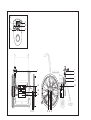
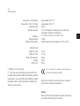
Gebrauchsanweisung
D
User’s Manual
GB
Mode d'emploi du dispositif e·fix
F
Instrucciones de uso e·fix
E
Istruzioni per l'uso di e·fix
I
Brugsvejledning
DK
Gebruiksaanwijzing
NL
Bruksanvisning e·fix
N
Bruksanvisning till e·fix
S
1
2
31
8
30
32
1
1
5
7
13
25
14
20
18
21 22
15 16 17
Contents
1
Introduction
1.1 Standard scope of delivery
1.2 Technical data
2
4
5
6.2 The first attempts at driving
6.3 Suggestions on driving with e·fix
6.4 Dangerous ground
27
27
29
2
Wheels
2.1 Mounting the wheels
2.2 Removing the wheels
6
6
7
7
7.1
7.2
7.3
30
30
30
3
Batteries
3.1.1 Inserting the batteries
3.1.2 Removing the batterie
3.2 Charging the batteries
3.3 Charging reserve batteries
3.4 Safety instructions for sliding window
3.5 Information on the batteries
8
8
9
10
11
12
13
4
4.1
4.2
4.3
4.4
4.5
Control unit
Prior to initial use
Push buttons and displays
Joystick
Adjustment
Swivel arm
14
14
16
20
22
23
5
Tilt supports
24
26
26
27
6
Operation
6.1 Safety of the driver
Driving
Driving with manually operated wheelchair wheels
Driving with e·fix wheels in manual mode
Driving with e·fix wheels in electrically
powered mode
7.4 Range
7.5 Transportation
8
8.1
8.2
8.3
Care, Maintenance and disposal
Cleaning
Maintenance
Disposal
Quick assistance when not functioning
correctly
9.1 Error messages on the display
9.2 Changing the battery's fuse
9
31
31
31
32
32
32
32
32
33
34
10
11
11.1
11.2
Control unit for attendants
Warranty and liability
Warranty
Liability
34
36
36
36
12
Index
37
Congratulations
With the acquisition of your e·fix you chose a reliable,
multifunctional, state of the art
product based on
most current technology.
In the event of further questions, please contact your
local dealer or any
distributor.
Have fun with your e·fix,
2
The e·fix increases your independence and mobility
tremendously. Used appropriately, it will soon prove
indispensable and open up entirely unexpected possibilities
to you. Mounted to your wheelchair you virtually got a
powered wheelchair without the disadvantages of the latter.
For instance your wheelchair remains fully foldable, which
is particularly important for its transportation and the often
only restricted space available.
Please read the instruction manual carefully to get familiar
with the system and its variety of possibilities. Handling
the e·fix is much less complicated than it may seem when
reading the instructions for the first time. As a matter of
fact, you will instantly realize just how easy and effortless
it is to use the e·fix when your alber distributor teaches
you step by step the practical handling of it. This instruction
session is part of the alber service and free of charge.
your
team
Important safety instructions Please observe them closely!
In the interest of your safety, the e·fix may only be operated
by people who:
3
· have been taught how to use the e·fix
55
· are physically and mentally capable to use the e·fix in
all possible situations of employment
The instruction session is part of the delivery package. It
takes place by appointment and is done by your local dealer
or one of the
distributors, no extra charge involved.
If for some reason you still do not feel comfortable handling
the e·fix, please contact your local dealer.
Please also observe the maximum slope your wheelchair can
handle determined by the wheelchair manufacturer. Do not
exceed it.
· The efficiency of the additional drive may be affected by
electromagnetic fields, generated for example, by mobile
telephones.
The additional drive therefore, should be switched off if
mobile telephones are being used in the close vicinity of
the wheelchair.
· The additional drive can also affect other equipment such
as theft-proof cabinets in departmental stores.
Do not use the e·fix before you participated
in the instruction session.
1.1
Standard scope of delivery
Optional accessories
4
· 2 e·fix wheels
· Swing out holding device for control unit
· Control unit with holding device
· Tilt supports
· Batteries plus bag
· Control unit holding device for attendant
·
· Spoke guard
charger
· Distributor interface
· Joystick modification
· Hand rest - control unit
· Adapter for loading batteries when removed from wheelchair
· Charger adapter
· Battery pack 12V /17Ah
· Long hand rest
· Protective bracket for control unit
· Therapy table
1.2
Technical data
Batteries:
Charging voltage:
Operating temperature:
approximately 12 km (**)
approximately 22 km (**)
6 km/h
18 % (if 120 kg load is added, please stay within the
wheelchair manufacturer's limitations)
2 x 12 Volt / 12 Ah or 2 x 12 Volt / 17 Ah
24 Volt
ambient temperature range [approx.-15 °C / +45 °C)
Weight of parts
Batteries 12 Ah:
Batteries 17 Ah:
Wheel with hub motor:
Charger:
Control unit:
8,7 kg
13,2 kg
8,0 kg
1,0 kg
0,4 kg
Range with a 12 Ah battery:
Range with a 17 Ah (*) battery:
Maximum speed:
Maximum gradient:
(*) Batteries 17 Ah is optional
(**) The range varies depending on the ground and the
prevalent driving conditions. With optimal driving conditions
(among others, even ground, fully charged batteries, ambient
temperature 20 °C, constant speed) the indicated travel
distances can be reached.
The e·fix complies to the guidelines for medical products of
the European Community 93/42/EWG.
We reserve the right for technical changes or changes in
design due to continuous development.
Charger
Please consult the enclosed operator's manual of the charger
for technical information and instruction.
5
2
Wheels
2.1
Mounting the Wheels
6
15
17
The two electrically powered wheels are the heart of the
e·fix. The wheelchair's standard manual wheels are exchanged
with the e·fix wheels as follows. Please lift the wheelchair
somewhat.
· Remove the wheelchair's left wheel according to the
wheelchair's user's manual.
21
· Take an e·fix wheel and turn the coupling plate [15]
counter clockwise to position "I."
· Press the middle of the shutter [17] with your thumb so
that the inserted bow-type handle [16] pops out.
· Pull out the bow-type handle all the way.
16
· Insert the stub axle [21] of the e·fix wheel approximately
halfway into the wheel receiver [24]. In this position the
bow-type [16] handle juts out about 5mm above the
shutter [17].
· Turn the e·fix wheel until the torque plug [22] on the
wheel and the torque socket [23] on the holding device
on the wheelchair are vis-à-vis each other.
16
· Now insert the e·fix wheel all the way into the wheel
receiver [24]. Also make sure that the torque plug [22]
on the wheel is inserted into the torque socket [23] on
the holding device at the same time.
· Check whether the wheel is locked into place by pulling
on it. If the bow-type handle [16] folds all the way into
the shutter [17], the wheel is locked properly.
· Repeat all these steps to mount the e·fix wheel on the
other side.
2.2
Removing the Wheels
If you want to transport the wheelchair, you can remove the
e·fix wheels and fold the wheelchair.
Before driving always make sure that both
wheels are properly locked (switch position
I). Faulty connec-tions show on the display
of the control unit (see chapter 9.1) and lead to an
immediate standstill of the system.
· Turn the coupling plate [15] of the left wheel counter clockwise
to position "I."
· Press the middle of the shutter [17] with your thumb, so that
the inserted bow-type handle [16] pops out.
· Pull out the bow-type handle [16] all the way.
· Lift the wheelchair up a bit and pull the wheel out of its
receiver.
· Insert the bow-type handle [16] back into the shutter [17].
· Repeat all to remove the e·fix wheel on the other side.
Please avoid damage at the stub axle [21] of the
wheels, particularly when transporting the
wheelchair.
22 21
23
24
7
3
Batteries
· Connect the interface [25] as shown in the drawing to
the batteries. Make sure that the cables are inside the
opening [26].
3.1.1
Inserting the batteries
It is standard that the manufacturer attaches the specifically
designed bag intended for the batteries to your wheelchair
when the e·fix is mounted.
8
26
20
b
· Place the batteries [20] as shown in the drawing in the
battery bag [18] (connection socket of the interface
points forward).
18
19
· Secure the battery bag [18] with the Velcro fastener [19].
Make sure that the Velcro fastener fits as tightly as possible
to the housing of the batteries.
b
20
18
25 26
3.1.2
Removing the batteries
The batteries only need removing when the wheelchair
requires folding for transportation. The battery bag can
remain on the wheelchair and does not require removing.
Never use batteries other than those checked
and provided by alber. The use of other batteries
can cause damage to the electronics or result
in the malfunctioning of your e·fix.
· Remove the interface [25] as shown in the drawing from
the batteries.
· Open fully the Velcro fastener [19] of the battery bag
[18] and remove the batteries.
· Store the batteries [20] in a safe place.
· Close the sliding window on the interface if still open.
· Fold the battery bag as illustrated in the drawing, inserting
the interface [25] into it.
25
9
3.2
Charging the batteries on the wheelchair
Charging the batteries in the car
· Open the sliding window [27] on the interface.
When transporting your wheelchair in the car, you will most
often remove the e·fix-wheels and the batteries from the
wheelchair due to restricted space. The batteries can be
charged while driving the car by using the cigarette lighter
socket and a car charge converter which is available at a
car or electrical shop.
· Insert the plug of the alber charger into the charging
socket [29].
· Insert the adapter [a] into the connection socket [b] of
the battery pack.
After using the e·fix for a longer period of time, the batteries
need recharging. There is no need to remove the batteries
from the battery bag for this purpose.
10
d
e
b
a
c
27
29
12 Volt
f
· Connect the charger to a mains power supply.
Close the sliding window of the interface
after charging.
· Insert the plug [c] of the alber charger [e] into the
charging socket [d] on the adapter [a].
· Connect the charger [e] to the charge converter [f].
· Connect the charge converter [f] to the cigarette lighter
of your car.
· Observe the operating instructions enclosed with the
charge converter.
· Close the sliding window of the interface after charging.
Switch off the battery charger when charging is completed.
· Withdraw the battery charger plug [41] from the socket
[38].
· Pull the charging adapter [40] out of the battery pack
[20].
Always make sure that the batteries are recharged when the
e·fix has been used for a longer period of time. If the e·fix
is not being used, keep the batteries connected to the
charger. The
charger automatically switches to a
mode retaining the charge, whenever the batteries are fully
charged. Thus, it is impossible to overcharge and/or damage
the batteries.
Please note the operating instructions supplied
with the battery charger.
3.3
Charging reserve batteries
A second (optionally available) battery pack can be charged
with the charging adapter [40] while the battery pack
located under the wheelchair is being charged via the e·fix
interface (see chapter 3.2).
· Insert the charging adapter [40] into the connection on
the battery pack [20] as illustrated in the drawing.
· Insert the battery charger plug [41] into the socket [38].
· Connect the charger to a mains power supply and switch
on the battery charger.
38
40
41
20
11
3.4
Safety Hint on the sliding window
Important Safety Hints - please observe !
· Always keep the sliding window of the interface closed!
12
· Only open the sliding window when connecting the charger
and/or changing the fuse. Close the sliding window again!
Should liquid enter the interface (e.g. due to leakage),
remove it immediately from the accumulator. For safety
reasons, have the interface checked by your specialist dealer
before using again.
3.5
General Information on the Batteries
The batteries of your e·fix are maintenance-free and
rechargeable. Their durability depends considerably on the
charging/discharging cycles. You can increase their durability
by taking care of them properly such as recharging them
regularly. The built-in electronics of the e·fix test the
charge of the batteries continually; thus, avoiding a total
discharge of them, always provided that they are used
correctly.
· Avoid a total discharge of the batteries. Recharge the
batteries of the e·fix after each partial discharge, i.e.
after each use.
· Lead batteries are subject to a so-called self-discharge.
Therefore the batteries should, when-ever possible, always
be connected to the
automatic charger. The alber
automatic charger switches from charging to maintaining
the charge once the batteries are fully charged, which
means that the batteries cannot be overcharged.
· If you store lead batteries over a longer period of time
without regularly recharging them, they suffer a reduction
of capacity. However, after several recharging/discharging
cycles they recover their full capacity.
· Incorrect handling of the battery may result in the leakage
of electrolytic liquid.
This may cause injuries to the skin or damage clothing.
· Should skin or eyes come into contact with the electrolytic
liquid, rinse immediately with clear water and consult a
doctor.
· Do not expose the battery to fire or burn.
This may cause the battery to explode.
· Do not short circuit the battery. A short circuit causes
extremely high currents which may damage the battery
or the device.
· After expiry of the service life, return the battery to
or the
specialist dealers who will dispose of it
correctly.
The batteries of your e·fix can be recharged
or discharged in any position. They are
considered as safe as dry batteries and certified
for airline transportation by DOT and IATA.
13
14
4
Control unit
4.1.1
Removing the control unit
4.1
Prior to initial use
· Deactivate the e·fix by pressing the On/off switch [8] –
the display goes out [2].
The standard delivery package of the e·fix includes mounting
its various components. It is, however, advisable to remove
several compo-nents from the wheelchair, for instance, if
you want to transport the wheelchair in your own car. You
gain more space or make better use of the existing space
in your trunk.
· Pull the plug [5] from the control unit.
· Remove the control unit [1] including the connection
pipe [7] from its holding device[13].
· Place the plug of the control unit in the battery bag [18].
· Keep the control unit [1] in a safe place during transport.
2
8
An alternative method is to remove the control unit [1]
from the offsetting component [32] so that an accompanying
person can operate it from a bracket at the rear of the
wheelchair (see Chapter 10).
4.1.2
Installing the control unit
· Remove the plug of the control unit from the battery bag
[18] and insert it in the socket [6] on the control unit.
· Withdraw the plug [5] from the control unit.
· Release the clamping lever [33].
· Slide the control unit [1] out of the offsetting component
[32].
· Insert the connection pipe [7] together with the control
unit in the mount [13] on the wheelchair.
Proceed as follows if the control unit for the control system
has been removed from the offsetting component [32] by
an accompanying person:
· Slide the control unit [1] into the offsetting component
[32].
· Tighten the clamping lever [33].
· Insert the plug [5] into the control unit [1].
· Your e·fix is now ready for use again.
15
4.2
Push buttons and displays
4.2.2
Displays
After switching on the e·fix and on completion of the
automatic system check, various messages appear in the
display [2]:
4.2.1
On/off switch
16
Use the button [8] to switch the e·fix on and/or off.
When switching on the e.fix, the electronic system automatically checks the operability of all components. Varying
symbols simultaneously appear in the display which go off
when the check was fault-free.
8
4
2
30
31
32
· The bar display [4] shows the charging state of the
batteries.
Five black bars indicate that the "battery is charged 100%",
four black bars indicate that the "battery is charged 80%",
three black bars indicate that the "battery is charged 60%"
etc.
Make sure that the batteries are recharged in time so that
you can always get the most out of your e·fix. Please check
Chapter 3.2 for information on charging the batteries.
· The function Indoor/outdoor is permanently displayed by
the symbols "0" and/or "I" (see Chapter 4.2.5).
· The lighting of the display goes off 30 seconds after
switching on the e·fix, is reactivated however, in case
of a sudden error message.
· If the symbol
and the Code 14 or 15 appear and an
intermittent tone is heard, the wheels are not engaged.
Engage the wheels (see Chapter 7.3)
· If the symbol
as well as Code 4 or 5 appear and a
continuous tone is heard, the wheels are not correctly
positioned in the wheel receivers.
Insert the wheels correctly in the wheel receivers on the
wheelchair (see Chapter 2.1)
· If the control unit is switched on but the e·fix is not
being used, it switches off automatically after 1 hour.
The switch-off period can be adjusted according to your
requirements by a specialist dealer for medical accessories.
(see Chapter 4.2.6).
Should the system check detect a system failure, this will
be indicated in the display and an acoustic signal is
simultaneously emitted. A list of all possible error messages
can be found in Chapter 9.1.
4.2.3
Adjustment wheel for selecting the speed
The speed which the e·fix should achieve when the joystick
is pushed as far as it will go, can be selected infinitely
variably at the adjustment wheel [30]. The adjustment range
is between 0.6 km/h and 6 km/h.
Wheelchair drivers who use the e·fix for the
first time, should begin at a low speed (see
also Chapter 6.2).
4.2.4
Horn
In order to signalize a dangerous situation, the horn can
be activated via the button [31].
· If the button [31] is pressed, a permanent acoustic signal
can be heard.
· If the button [31] is released, the signal stops.
17
4.2.5
Indoor/Outdoor button
By pressing the Indoor/Outdoor button [32], the wheelchair
driver has two factory-set parameter combinations.
When Indoor is activated a "I" appears in the display [2],
when the Outdoor function is activated, a "0" appears.
See table below:
18
7
Function
Indoor setting
Outdoor setting
Max. speed forwards
60% = 3,6 km/h
100% = 6 km/h
Max. speed backwards
60% of the maximum speed = 2,2 km/h
60% of the max. speed = 3,6 km/h
Acceleration time
2,0 sek.
1,5 sek.
Delay time
2,0 sek.
1,5 sek.
Rotation speed
31 % of maximum speed
28 % of maximum speed
Rotation acceleration/delay
0,31 sek.
0,31 sek.
Buzzer
Active
Active
In case of brake
Time delayed by 30 seconds
Time delayed by 30 seconds
Automatic switch-off time
1 hour
1 hour
Joystick stroke
100 %
100 %
4.2.6
Programming possibilities
The parameters set in the previous chapter, can be adapted
to the individual requirements of the wheelchair driver and
are as follows:
· Maximum speed forwards - the maximum speed that can
be reached when the joystick is pushed as far as it will go
· Maximum speed backwards - the maximum speed that can
be reached when the joystick is pushed as far as it will go.
· Acceleration time - the period of acceleration from standstill
or the driving speed to the set maximum speed.
· Delay time - the period of braking from the maximum
speed to the desired support level or standstill.
· Rotating speed - maximum speed in which the wheelchair
can negotiate an arc / curve
· Rotation acceleration / delay - period of time of
acceleration and/or delay when driving a curve
· Buzzer - activation or deactivation of an acoustic signal
· Braking onset – the time between the last issuance of a
driving command until the electromagnetic brakes are
applied.
· Automatic switch-off time - the period of time in which
the e·fix remains ready to operate without switching off
automatically for the purpose of saving energy.
· Joystick stroke - pushing the joystick as far as it will go
to achieve a drive command.
Please contact your specialist dealer for the
individual adaptation of your functions. He
will be only too pleased to advise you and
program your settings.
19
4.3
Joystick
The joystick of the e·fix can be compared to a fictional
combination of steering wheel, clutch and gas pedal of a
car. Basically all of the wheel-chair driver's control commands
are directed to the e·fix wheels by the joy stick. That's why
driving the e·fix takes some practice. Please use the lowest
speed when you drive the e·fix the first couple of times
The wheelchair curves to the
right driving forward.
(The curve's radius depends
on the joystick's movement).
20
The wheelchair turns to the
right on the spot.
Performance (from the driver's point of view)
The wheelchair drives
straight forward.
The wheelchair curves to the
left driving backwards.
(The curve's radius depends
on the joystick's movement).
The wheelchair drives
straight backwards.
The wheelchair curves left
driving forward.
(The curve's radius depends
on the joystick's movement).
21
The wheelchair curves to the
right driving backwards. (The
curve's radius depends on
the joystick's movement).
The middle position of the joystick remains without function,
i.e. the wheels do not move and are blocked by the builtin brakes. However, on slopes of more than 10 % you have
to tighten additional brakes that must be mounted to the
frame of the wheelchair.
The joystick functions in a way like the gas pedal of a car.
Between its original position (everything is at a standstill)
and one when it is fully pushed e.g. forward (maximum
speed) you can vary the speed.
The wheelchair turns to the
left on the spot.
Please refer to Chapter 6 and 7 when
undertaking your first driving attempts.
4.4
Adjustments
When the e·fix is mounted at an
plant, the control
unit is placed in the position indicated by the wheelchair
driver at the time he ordered the e·fix.
22
Generally this position is on the same height as the armrest
and cannot be moved vertically. By contrast, a horizontal
adjustment is easily possible, since the control unit's position
depends on the length of the driver's arm.
If it turns out that you would like a different
vertical position of the control unit from the
one you ordered, please contact your
representative.
4.5
Swivel arm (available as accessory)
· Withdraw the plug [5] from the control unit [1].
· Release the clamping lever [33] and slide the control unit
[1] out of the offsetting component [32].
To simplify driving to table edges, we recommend mounting
the optional swivel arm [12]. The swivel arm allows the
control unit to be swung out from its original position.
a
5
32 1
· Press the cap [a] and swing the control unit [1] out to
the side.
23
· To return, swing the control unit [1] back into the initial
position; the cap [a] moves upwards and automatically
locks the swivel mechanism.
· If the swivel arm and the control unit require removing
for e.g. transporting, they can be completely removed
from the mount [11]
· The control unit can be longitudinally offset a little more
if necessary in the offsetting component [32] itself by
releasing the clamping lever [33].
· After adjusting to the optimum position, secure by
tightening the clamping lever [33] on the offsetting
component [32].
33
12
4.5.2
Mounting the control unit on the swivel arm
· Slide the control unit [1] into the offsetting component
[32] and secure it with the clamping lever [33].
· Swivel the control unit to one side.
· Insert the plug [5] into the control unit [1].
4.5.1
Removing the control unit from the swivel arm
· Swivel the control unit to one side.
The swivel arm can be attached to virtually
all wheelchair models. Contact your specialist
dealer or representative for further details.
5
Tilt Support
· Secure the tilt support in the holding device [a] with the
quick pins [b]. Press the locking mechanism in the center
of the locking pin and push the pin entirely into the
holding device.
(available as optional accessory)
Since most wheelchairs come with tilt support, the
tilt support is available only as an optional accessory. If
we deliver the e·fix with tilt support, the latter is already
adjusted to your wheelchair.
· Check whether the quick pins [b] securely rest in the
holding device [a]. You are not supposed to be able to
remove them without pressing the locking mechanism in
their center.
24
· First remove the quick pins [b] from the holding device
[a] by pressing your thumb on the center of the pin while
lifting it out with your middle and index finger.
· To remove the tilt support, work your way back step by
step.
· Insert the tilt support [c] into the holding device [a].
(The tilt support for the left side is marked with an "L,"
for the right with an "R".)
b
a
c
a
a
b
b
b
c
The CE conformity for the e·fix is only valid in combination
with the tilt support. In addition, the following points
have to be taken into consideration:
· Assembly and repairs as well as any other work done on
the e·fix must be carried out by Ulrich Alber GmbH + Co. KG
or any other personnel authorized by
.
· The lower part of the tilt support must be attached high
enough so that their wheels can rotate freely when the
wheelchair is on a horizontal level.
Important safety note
Due to blows or impact caused, for example, by
unintentionally setting down on too high kerbs, particularly
the toothed sections [d] in the tilt supports may be subject
to above average loading. Consequently the condition of
the teeth (see illustration for the precise position) should
be checked at least once a week.
25
· The user must pay particular attention to the following:
a) The tilt support must be unobstructed.
b) Please be extra careful when driving over obstacles
higher than 40 mm and narrower than the sidewalk's curb.
c) The critical height of obstacles must be tested
individually for each wheelchair equipped with the e·fix
by his/her driver.
d) The point at which a certain wheelchair equipped with
the e·fix tilts backwards at its back axle must also be
tested by its user. The critical limit is reached at the
point where the tilted wheelchair falls backwards.
Driving the e·fix without attached tilt support
is not safe, thus not admissible.
d
d
Condition of toothed section
Swivel the tilt supports as shown:
· Toothed section [d] sits tight within the holder [e] and
the adjusting tube [f] and cannot be twisted: tilt supports
can continue to be used.
· Toothed section [d] can be twisted within the holder [e]
or the adjusting tube [f]: teeth are twisted – replace tilt
supports immediately!
26
Undamaged teeth:
tilt supports can continue to be used.
e
f
Teeth twisted:
replace tilt supports immediately!
6
Operation
6.1
Safety of the Driver
Safety and comfort of the driver are the first priority. It
is, therefore, indispensable to get to know your e·fix and
its driving quality thoroughly. Your
representative
assists you with a free of charge training session when you
use the e·fix for the first time. He helps you until you feel
secure using your e·fix.
6.2
Driving
The first few attempts to use the e·fix should not take
place in a confined space, since the driver is not used to
the device and thus likely to collide with furniture and
such. Therefore, you should first practice driving the e·fix
outside, e.g. on a parking lot.
· Turn the e·fix on at its lowest speed (see chapter 4.2)
and get a feeling for its driving quality.
· Give yourself small driving tasks and practice them at
your own leisure.
more confident moving the joystick thus driving in a more
precise manner.
· Increase the speed slowly. We advise you always to choose
a low speed level when driving inside.
6.3
Further Suggestions to Drive with the e·fix
27
· When you start driving, never push the joystick all the
way forward. There is the potential danger of an accident,
especially if the pre-selected speed is set at maximum
speed. In such case the wheelchair may make movements
the driver cannot control anymore.
· Move the joystick gently and smoothly. Do not jerk the
joystick.
· Make sure you do not make strong, jerky movements of
the joystick, particularly in potentially dangerous situations
when you want to avoid an obstacle. Instead, brake the
e·fix until you come to a standstill.
· If you let go of the joystick, your wheelchair comes to
a gentle standstill. In case you need to come to an
immediate standstill, move the joystick briefly opposite
the driving direction and let go abruptly.
· To use the e·fix successfully comes with practice
· Practice results in competence. You will soon become
· Always brake the e·fix with the joystick; never touch the
grip rings of the wheelchair's wheels.
· Never drive parallel to steep slopes. The center of gravity
may change inadvertently, which may result in the
wheelchair‘s tilting sideways.
· Counter-steer as necessary when you are driving along
sloping curbs etc.
28
· Always drive over small obstacles such as curbs in a 90
degree angle; in other words, both wheels drive over the
obstacle at the same time. Go at a low speed over the
obstacle.
· Check regularly the right-angled alignment of the front
wheels to the ground. Also check regularly the wheels' air
pressure. Both influence the driving quality and the range
of the e·fix.
· Never drive the e·fix without tilt support. Remove the
latter only when you drive over a bigger obstacle. In such
case you need a person accompanying you, since there
is an increased danger for the wheelchair to tip over.
· Driving on public roads is subject to Motor Vehicle
Regulations. Your wheelchair must be equipped with the
obligatory additional devices determined by the regulations
of your country.
Please note that the driving quality and the
brake reaction is also influenced by the two
front wheels. Therefore, please make sure that
there is the same air pressure in both tyres and that
their axles are aligned in a 90 degree angle to the
ground.
6.4
Dangerous ground and dangerous situations
Taking into account his driving skills and physical abilities,
the e·fix driver decides for himself which routes he will
travel.
Prior to setting off he must check the e·fix for worn or
damaged tyres, as well as the state of charge of the batteries
and the proper functioning of the direction indicators.
These safety checks, as well as the requisite personal driving
skills, are particularly important near the following dangerous
ground, which should only be tackled at the discretion of
the e·fix driver:
Slopes with a maximum gradient of 18 % can
be driven on with the e·fix without the
assistance of an escorting person. However,
important prerequisites are faultless tyre treads, correct
tyre air pressure, a completely safe terrain and a
maximum load of 120 kg.
Slopes with a maximum gradient in excess of 18 %
must only be driven on with the e·fix with the
assistance of an escorting person. Here too essential
prerequisites are faultless tyre treads, correct air
pressure in all tyres, a completely safe terrain and a
maximum load of 120 kg.
An escorting person is also necessary for crossing
· Quay walls, landing and berthing points, paths and places
close to water, unsecured bridges and dikes
· kerbs with a gradient in excess of 15 %
· Narrow paths, sloping ground (e.g. ramps and driveways),
narrow paths beside inclines, mountain routes
· obstructions of all kinds on sloping ground as
there is a greater risk of tipping over in these cases.
· Narrow and / or sloping paths close to main arterial roads
or close to chasms
Particular care should always be taken when crossing
main arterial roads, cross roads and level crossings.
Never cross rail tracks in the road or at level crossings
by driving in parallel to them as the wheels could get
wedged in. If possible always ask some person to escort
you who can push you over the road or level crossing
in the event that you get stuck (e.g. due to the batteries
being empty).
· Leaf- and snow-covered or icy driving routes
· Ramps and lifting equipment on vehicles.
Great care should be taken in driving on ramps attached
to vehicles. During the lifting or lowering procedure
29
9.1
Error messages in the display
Code
Signal tone
Cause
Help
4 (! lights up)
Continuous tone
Communication wheel - left
5 (! lights up)
Continuous tone
Communication wheel - right
7 (! lights up)
Continuous tone
Battery voltage
- Insert left wheel correctly in the wheel receiver
- 25 A fuse defect
- left wheel defect
- Insert right wheel correctly in the wheel receiver
- Right wheel defect
Charge battery
14 (! flashes)
Intermittent tone
Coupling at left wheel not engaged
Engage left wheel
15 (! flashes)
Intermittent tone
Coupling at right wheel not engaged Engage right wheel
16 (! flashes)
Intermittent tone
Left wheel overheated
18 (! lights up) Continuous tone
Right wheel exceeds operating
temperature
Left wheel overloaded
Allow left wheel to cool down
(Observe operating temperature)
Observe operating temperature, reduce
wheel to operating temperature
Allow right wheel to cool down
(Observe operating temperature)
Observe operating temperature, reduce
wheel to operating temperature
Switch system off and on again
19 (! lights up) Continuous tone
Right wheel overloaded
Switch system off and on again
16 (! lights up) Continuous tone
17 (! flashes)
Intermittent tone
17 (! lights up) Continuous tone
Left wheel exceeds operating
temperature
Right wheel overheated
If an error cannot be eliminated by following the above and/or another error code is displayed, please contact
your specialist dealer.
33
9.2
Changing the battery's fuse
If excessive strain is put on some of the e·fix components,
in rare cases you may have to change the fuses of the
batteries which do not require moving from the wheel chair
for this purpose.
34
25
25
· For safety reasons, remove the interface from the batteries
(see Chapter 3.1.2)
3
27
· Open the sliding window [27] on the interface [25]
· Remove the defect fuse (25 A or 3 A ) from the mount.
10
Control unit for attendants
(as optional accessory)
· Insert a new fuse in the mount.
· Close the sliding window [27].
· Connect the interface again to the batteries (see chapter
3.1.1).
· Re-start the e·fix.
Fuses react extremely sensitively to electrical
faults. If you have to change a fuse several
times, this could mean that an e·fix component
is faulty. In this case, please contact your specialist
dealer.
e·fix can be operated by both the wheelchair driver or
his/her attendant. Simply move the control unit from its
regular location at the armrest of the wheelchair to the
control panel which is not part of the standard scope of
delivery but can be subsequently attached when required.
· If the e·fix is ready for operation, deactivate the system
by pressing the On/Off switch on the control unit (see
Chapter 4.2.1).
· Withdraw the plug [5] from the control unit (see also
Chapter 4.1.1)
· Withdraw the control unit from the offsetting component
[32] (see also Chapter 4.1.1)
· Slide the control unit [1] into the offsetting component
[32] and secure it with the clamping lever [33].
· Insert the plug [5] into the control unit.
Dismantle the control unit in reverse order if it is to be
used again directly by the wheelchair occupant. You can
decide which of the individual components [32 - 36] should
remain affixed to the wheelchair for use when the necessity
arises.
· Insert the assembled unit into the mounting [34].
· Finally, slide the angle mounting [35] onto the securing
feature [37] on the wheelchair.
· Secure the angle mounting [35] with the clamping lever
[36].
5
1
33 32 34
35
37 36
35
11
Warranty and Liability
36
11.1
Warranty
11.2
Liability
The time of warranty for the e·fix amounts to 24 months
(6 months for the batteries) from the date of purchase, and
covers faulty material and processing defects.
The warranty does not include:
Neither Ulrich Alber GmbH + Co. KG nor its agents or
authorized dealers and sales representatives will be liable
for the safety, reliability or performance of the e·fix or for
any claims for personal injury or property damage which
may arise from the following:
· natural wear and tear
· The e·fix was driven without tilt support.
· damage caused by improper use
· The e·fix was handled and used inappropriately.
· forced damage
· unauthorized changes made on the device and/or its
accessories
· The e·fix was used other than in accordance with all
instructions and precautions included in the operator's
manual and on the product labeling.
· The e·fix was not checked every two years by an authorized
dealer or Ulrich Alber GmbH + Co. KG.
· Assembly, repairs and other work was done by unauthorized
personnel.
· Parts or accessories other than those recommended by
the manufacturer of the e·fix were used.
· Parts of the e·fix were changed or removed entirely.
12
Index
A
Adjustments
Adjustment wheel for selecting speed
B
Batteries
Bag for the batteries
Bow-type handle
C
Changing the battery's fuse
Charging the batteries
Cleaning
Condition of toothed section
Control unit
Coupling plate
D
Dangerous ground/situations
Displays
Driving
Driving with manually operated
wheelchair wheels
Driving with e·fix wheels
Driving with e·fix wheels electrically
powered operation
22
17
8
8
6
34
10
32
26
14
6
29
16
30
30
30
31
E
Error messages in the display
33
F
Further suggestions to drive with the e-fix
27
37
G
General information on the batteries
13
H
Horn
17
I
Indoor/Outdoor button
Installing the control unit
Inserting the batteries
18
15
8
J
Joystick
20
L
Liability
36
M
Maintenance
Mounting the wheels
32
6
38
O
On/Off Switch
Operation
16
27
P
Performance
Programming possibilities
Push buttons and displays
20
19
16
R
Range
Recycling
Removing the batteries
Removing the control unit
Removing the wheels
31
32
9
14
7
S
Safety instructions
Safety of the driver
Speed
Standard delivery package
Stub axle
Swivel arm
3
27
17
4
6
23
T
Technical data
Tilt support
5
24
Tilt support – important safety note
Torque socket
Transportation
25
6
31
W
Warranty
Wheels
36
6
20.0001.4.01.03
Ulrich Alber GmbH + Co. KG
Vor dem Weißen Stein 21
72461 Albstadt-Tailfingen
Telefon (07432) 2006-0
Telefax (07432) 2006-299
www.ulrich-alber.de