1
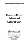
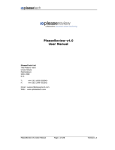
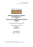
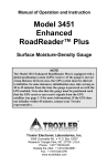
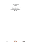
TABLE OF CONTENTS MODULE I: NUCLEAR GAUGE DESIGN, THEORY AND OPERATION Objectives .....................................................................................................2 Section 1: Design .........................................................................................3 Section 2: Theory .........................................................................................5 Section 3: Operation ....................................................................................9 In Nuclear Gauge Train-the-Trainer Course, 2000, USDA-Radiation Safety Staff, Beltsville, MA. Author: Steven R. Evett, Soil Scientist, USDA-ARS, Water Management Research Unit, Conservation and Production Research Laboratory, Bushland, TX, 79012. E-mail: [email protected] Web site: http://www.cprl.ars.usda.gov/programs/ The mention of trade or manufacturer names is made for information only and does not imply an endorsement, recommendation, or exclusion by USDA-Agricultural Research Service or USDARadiation Safety Staff. The United States Department of Agriculture (USDA) prohibits discrimination in all its programs and activities on the basis of race, color, national origin, gender, religion, age, disability, political beliefs, sexual orientation, and marital or family status. (Not all prohibited bases apply to all programs.) Persons with disabilities who require alternative means for communication of program information (Braille, large print, audiotape, etc.) should contact USDA’s TARGET Center at 202-720-2600 (voice and TDD). To file a complaint of discrimination, write USDA, Director, Office of Civil Rights, Room 326-W, Whitten Building, 14th and Independence Avenue, SW, Washingtion, DC 20250-9410 or call 202-7205964 (voice or TDD). USDA is an equal opportunity provider and employer. Nuclear Gauge Design, Theory and Operation 1 MODULE I: NUCLEAR GAUGE DESIGN, THEORY AND OPERATION In Module I, the following objectives will be met: 9 Describe the five basic components of a nuclear gauge. 9 Describe the two geometries used for measurements. 9 Name the radionuclides used in moisture/density gauges and neutron moisture meters. 9 Describe the basic operation of these gauges 9 Learn procedures for safe gauge operation 9 Understand how effective gauge use supports the ALARA principle Nuclear Gauge Design, Theory and Operation 2 MODULE I: NUCLEAR GAUGE DESIGN, THEORY AND OPERATION Section 1: Design Gauges are designed to be portable devices for measuring moisture or density or both. They are fairly rugged and consist of a housing that includes the following components: Radioactive source(s), fixed or movable (probes) Shields, lead and tungsten for photons, plastic for neutrons Radiation detectors (sometimes movable and cabled to the housing) Computer/datalogger Display The electronics include: A power supply (internal battery, and associated recharge devices and AC adapter if battery is rechargeable) High voltage modules to power detector(s) Detector(s) Amplifiers Pulse shapers to convert detector discharges to computer detectable signals Microprocessor/counter/memory Most newer gauges have an impact resistant plastic carrying case which has proper labels and markings for the transport of the gauge. Example of Troxler moisture/density gauge Gauge with source rod secured Nuclear Gauge Design, Theory and Operation Base of gauge 3 Example of CPN profiling neutron moisture meter resting on depth control stand Example of Troxler profiling neutron moisture meter resting on depth control stand Key components of CPN 503 DR gauge Cross section of CPN 503 DR gauge showing heights (inches) of parts relative to the base Nuclear Gauge Design, Theory and Operation 4 MODULE I: NUCLEAR GAUGE DESIGN, THEORY AND OPERATION Section 2: Theory Gauges use photon emitting radioactive material to measure density and/or they can measure moisture using a neutron emitter. Some gauges have dual radioactive sources that can measure both density and moisture. Density Measurement If the gauge measures density, the radioactive material will be a photon emitter (gamma emitter). The usual radioactive source is Cesium-137 (137Cs). The source is permanently housed within the gauge or, on many models, is located at the end of an extendable source rod. If it is on a source rod, the 137Cs has two positions, retracted (in the housing) or extended to one or more preset depth positions. If the source is extended, it is placed in a hole in the material to be measured (media, usually soil) directly below the gauge. The extended source and the retracted source both depend on the photons traveling from the source, interacting with the surrounding material, and being detected by Geiger Muller (GM) detector(s) located within the body of the gauge. The extended source creates a geometry in which the photons travel, through the media to be measured, to the detector. This is referred to as direct transmission. If the source is within the body of the gauge (the source rod is not extended or is permanently fixed in the gauge), the geometry is called backscatter. Example of Direct Transmission Example of Backscatter Geometry In both geometries, photons leave the source in all directions. The density measurement is dependent on water content and should be corrected for it. The density measurement may also be affected by the chemical composition of the medium. Fly ash, coal, cementitious materials, some Nuclear Gauge Design, Theory and Operation 5 clays (mica), and other materials may require separate calibrations. Constituents that interfere with moisture measurements (see below) will also interfere with water content based corrections of density readings. In the backscatter geometry, of the photons that travel down into the media, some will interact with the electrons and scatter in new directions. A small fraction will be reflected back toward the GM detectors in the gauge housing and be detected. The value of density can be calculated based on how many of the photons are detected by the GM tube. The density measurement is only effective (90%) for approximately the first four inches of material under the gauge. The exact depth of measurement is unknown. In the direct transmission geometry, a hole is drilled or punched into the media and the source rod inserted. Photons are emitted in all directions, some directly toward the detector. The more dense the material, the fewer photons will reach the detectors. Of the photons that reach the detector, only a small portion have been backscattered. The radiation detected by the GM tubes is used to calculate the density. The depth range over which density is measured is known. Moisture Measurement Moisture measurement is actually a measure of hydrogen containing (hydrogenous) material. Water (H2O) contains a large amount of hydrogen as do petroleum and other hydrocarbons. The radiation in this case is high-energy (fast) neutrons and the interaction is with the similar sized nucleus of hydrogen atoms. The detector is a gas filled chamber that is sensitive, not to high-energy neutrons, but to very low energy (thermalized) neutrons. The source and detector are fixed in position relative to each other; and are contained in the gauge housing in the case of moisture/density meters, or in the probe in the case of profiling neutron moisture meters (NMM). The measurement technique uses the backscatter geometry. The neutron source contains two materials, which are: Radioactive, americium-241 (241Am) Non-radioactive, beryllium (Be). This mixed source is commonly called "Amby". The 241Am emits alpha particles and some photons. The photons are irrelevant to the gauge operation but can be measured and are important from a radiation protection perspective. The alphas are important in that they initiate the process that results in neutron emission. Since the 241Am and Be are intimately mixed together in the sealed source capsule, the alphas never escape. They do strike the Be and, in a process called "alpha in, neutron out", cause the Be to release a high-energy neutron [9Be(α,n)12C]. The individual neutrons may have any of several energies but they average about 5 MeV, or 5 million electron volts. These high-energy neutrons are emitted in all directions. Of the ones that enter the media to be measured, a small portion will interact with hydrogen nuclei and lose energy and change direction. The process of losing energy is called elastic scattering. Some of the neutrons will lose energy and become "thermalized". A thermal neutron has reached the mean temperature of the material, and has an energy of about 0.025 eV. The detector is blind to high-energy neutrons, but is sensitive to thermalized neutrons. So, the thermalized neutrons that scatter back into the detector will be measured. The detector itself is not a GM, which measures photons; it is a chamber filled Nuclear Gauge Design, Theory and Operation 6 with helium-3 (3He) or boron trifluoride (BF3) gas. For a moisture/density gauge, moisture detection is limited to about the first ten cm (four inches) of soil under the gauge when the soil is wet, increasing to about 25 cm (10 inches) when the soil is dry. For a profiling NMM, the radii of influence are equivalent to these ranges for equivalent ranges of water content. Because the thermalized neutrons are present in greater concentrations closer to the source, the measurement is biased towards the water content of soil nearest the source. For this same reason, the distance and orientation between the source and detector (called source-detector geometry) has a great effect on the calibration. Although the fast neutrons are most efficiently slowed by hydrogen atoms (about 19 collisions on average), they do interact with other atoms as well. This is why soil density and chemical composition affect the gauge calibration. Some elements, such as cadmium, boron, chlorine, and iron, are neutron absorbers. The latter three are important in some soils. The presence of absorbers changes the calibration and renders it less precise. Carbon and nitrogen are relatively efficient as neutron thermalizers (about 120 and 140 collisions on average, respectively). They are sometimes present in sufficient quantity to affect the calibration. Statistics of radioactive decay, gauge testing, and computations Radioactive decay is a random process that occurs according to a Poisson probability distribution. An important property of the Poisson distribution is that, for a series of counts over equal time periods, the square of the standard deviation is equal to the mean value. For a properly operating gauge, the mean of a series of counts (with the probe in a constant environment) should equal their standard deviation squared. The sample mean, m, is computed as m = (Σ x)/N where x is the value of a single count and N is the number of counts. The sample standard deviation, s, is computed as s = {[∑ (x - m)2]/(N - 1)}1/2 The ratio of s/(m)1/2, called the Chi ratio, should be close to unity for any sample. This ratio is related to χ by s/(m)1/2 = [χ2/(N - 1)]1/2 The spread in values of χ2 for a given probability level is given in statistical tables for different values of (N - 1), allowing us to write the right-hand-side of the above equation for the upper and lower limits of χ2 and thus obtain upper and lower values of the Chi ratio for the chosen probability level and number of samples. For a 95% probability level and 32 samples the Chi ratio should be between 0.75 and 1.25 about 95 times in every hundred. [Note that some gauges divide the count by a fixed number in order to reduce the displayed count to a reasonably small value. If the above calculations are applied to such reduced counts, the Chi ratios computed will be incorrect. To compute Chi ratios, the user should first multiply the recorded counts by the number that the gauge used to reduce them - see the users’ manual.] Nuclear Gauge Design, Theory and Operation 7 These facts allow the user to check gauge operation by computing the Chi ratio. In fact, all modern gauges include an internal function for doing so, either through a special “STAT” function, or as a normal part of taking a standard count. The range of the Chi ratio for a particular gauge will depend on the number of samples that that particular gauge uses in computing the standard count and Chi ratio values. An everyday part of gauge use should be to invoke this function in order to check gauge performance. An occasional Chi ratio outside of the 95% range is no large cause for concern, but should be checked by making another test. However, a string of Chi ratio values that average above or below unity signals a problem in the gauge electronics or internal geometry, and indicates inaccurate readings. For this reason, it is recommended that a standard count, including the Chi ratio, or a STAT test be obtained before daily use, and that these values be recorded. It is preferable to record the values in a spreadsheet to ease comparison of values over the long term. Note that even if the Chi ratio remains near unity, a sudden change in standard count signals a problem with the gauge that should be corrected before more field readings are taken. Possible problems include failure of electronic components including cable and connectors, and detachment of the detector tube inside the probe (change in geometry of measurement). Calibration equations for moisture/density gauges and NMMs are typically linear functions of a count ratio, CR. The value of CR is the ratio of the count, x, made in the measured material to a standard count, xs. CR = x/xs The standard count is taken, in the case of MD gauges, with the gauge placed on its “calibration” block, or, in the case of NMMs, with the probe locked in the shield or in an access tube surrounded by a large volume of water. Using a count ratio, rather than a calibration in terms of direct counts, allows the same calibration equation to remain valid even as the source strength decays. The half life of 137Cs is 30.6 years and that of 241Am is 458 years. To maintain 0.1% accuracy for density measurements (137Cs) the standard count must be re-determined every two weeks. To do the same for moisture measurements the standard count must be re-determined every eight months. An accurate calibration may be used for many years by use of the standard count and count ratio. In summary, the statistical properties of nuclear transformations allow easy checks of basic gauge operation by performing standard counts and Chi ratio calculations. There are several reasons to record daily standard counts and Chi ratios when using a nuclear gauge. These all ultimately relate to achieving the ALARA exposure goal by ensuring that malfunctioning gauges are not used and that accurate calibration equations remain valid over the life of the gauge, thus avoiding the necessity of re-work. Nuclear Gauge Design, Theory and Operation 8 MODULE I: NUCLEAR GAUGE DESIGN, THEORY AND OPERATION Section 3: Operation This section describes the general operations of the two basic types of gauges used by USDA personnel: a moisture/density gauge and a profiling neutron moisture meter (NMM). For safety reasons, the user should read the manual for the particular gauge before using it. Not only will the manual give specific operating instructions that allow safe operation; but, following correct operating procedures will reduce incorrect results that cause tests to be repeated. This directly impacts the two most effective strategies for limiting radiation exposure ALARA: decreasing time and increasing distance. MOISTURE/DENSITY GAUGES The moisture/density (MD) gauges manufactured by Troxler Electronics Laboratories, Inc. (Troxler) and Campbell Pacific Nuclear International, Inc. (CPN) are very similar in design and function. The MD gauges have a vertical source rod that may be lowered into a hole in the material to be tested for direct transmission readings, or may be left in the upper, locked position (with the source inside the gauge) for tests by backscatter. The 137Cs photon (gamma ray) source used in density measurements is sealed in the bottom end of the rod. With the rod in its upper, locked position, the 137Cs source is surrounded by a lead shield on all sides but the bottom. On the bottom, a sliding tungsten gate completes the shielding. When the rod is lowered, the gate slides out of the way. The 241Am/Be neutron source is sealed within the gauge body. From a safety point of view, the 137Cs source is potentially more dangerous both because the photon radiation is more damaging to human tissue, and because of the potential for the movable source to be left outside of the gauge body and thus outside of its shielding. The gauges feature LCD screens and keypads for operator convenience in controlling and reading tests, are battery powered, offer data transfer via an RS232 cable to a computer, and come complete with “calibration” block, drill guide/scraper plate, and shipping case. The gauge internal computer usually comes with factory determined calibration coefficients for linear calibrations of moisture and density vs. neutron and gamma counts, respectively. These may be changed by the user following additional calibration. Pre-use inspection and standard counts Prior to transport to the field for use, inspect the gauge for damage, easy movement of the source rod, correct closure of the tungsten shield gate, plentiful battery charge, etc. Make sure that needed accessories are present, that the class A transport case is in good condition, and that the shipping papers are complete. This is also usually a good time to take a standard count because the standard can be taken on a reproducible surface. Place the “calibration” block on a smooth, Nuclear Gauge Design, Theory and Operation 9 clean, compacted surface. A concrete floor in a building is ideal because it is likely to be thick enough (10 cm, 4 inches) and is likely to remain dry. Using a reproducible surface is necessary because the block does not represent a quasi-infinite volume to the gauge. Place the gauge in correct position on the block, initiate the standard count, and step away from the gauge. The gauge should be at least 2 m (6 feet) away from any object, wall, etc., and at least 10 m (sixty feet) from any other radioactive source. There are two reasons for taking a standard count prior to every measurement session. The first relates to the 30.6 year half life of the 137Cs source. To maintain accuracy of 0.1%, a standard count must be taken every two weeks. The second relates to the ALARA principle. Taking the standard count daily greatly diminishes the chance that a damaged gauge will be used extensively for measurements that will have to be repeated. The standard count is essentially a self test. If the moisture and density counts are within 2% and 1%, respectively, of the prior four readings, then the gauge can be considered to be operating correctly. If either standard is outside these limits, repeat the test. If a repeat is also outside the limits then invoke the gauge’s statistical test procedure (see above). Be sure to record the standard counts (and Chi ratios when available). It is recommended that these be entered into a spreadsheet and compared to previous standard counts. Malfunctions of electronics will show up as deviations from the long term mean standard counts, and/or Chi ratios that do not average to 1. Moisture/density gauge accessories: Type A case, scraper/guide plate, drill rod, hammer, and rod removal tool Nuclear Gauge Design, Theory and Operation Type A transport cases for profiling neutron moisture meters 10 Measurements Density and moisture measurements may be made on soil, asphaltic concrete, cementitious concrete, or similar materials. Measurements on compacted fly ash, mining waste and some other materials may require separate calibrations. The MD gauges from both manufacturers comply with ASTM Standard Test Methods D2922 and D3017, Density and Moisture Content of Soil and Soil Aggregates in Place by Nuclear Methods, and with ASTM D2950, Density of Bituminous Concrete in Place by Nuclear Methods. Bituminous concrete is commonly known as asphalt. Direct transmission measurements may be made at depths ranging from 5 cm (2 inches) to 30 cm (12 inches), and are representative of the mean density of the material over the chosen depth range. Backscatter measurements penetrate to about 10 cm (4 inch) depth in most compacted materials, but may penetrate further in low density materials. Backscatter measurements are biased towards the density of material nearest the surface. This is true for backscatter moisture measurements as well. The MD gauges allow for backscatter density measurements of layers thinner than 10 cm (4 inches) if the density of the underlying layer has been previously measured (either with the gauge or from core samples). The computers in these gauges contain firmware that applies correction factors based on the density of the underlying layer entered by the user. One reason that the MD gauges measure both density and moisture is that the firmware corrects the density measurement for the moisture content. For all measurements, the drill guide/scraper plate should be used to level the surface prior to measurements. If the surface cannot be leveled, either a more suitable site for measurements should be chosen, or dry sand should be used to fill surface voids. Any filling of voids will affect accuracy, although not as much as if the voids had not been filled. If voids are large, another measurement site should be chosen. Leveling and/or void filling are especially needed for backscatter measurements. Prior to direct transmission measurements, the plate should be placed on the leveled surface and used to guide the drill rod as a hole is made in the surface. The hole should be made to at least 5 cm (2 inches) below the desired measurement depth. After the hole is drilled, scribe or mark lines on the surface to aid in placement of the gauge. The plate is the same size as the bottom of the gauge. After placing the gauge on the surface, lower the source rod to the desired depth. Never force the rod. If there is a problem lowering the rod, retract the rod to its upper, locked position and inspect the hole for debris. Repositioning the gauge on the surface may alleviate the problem. Once the rod is lowered, press the keypad to initiate the reading and step away from the gauge until a beep is heard indicating that the reading is finished. Do not leave the gauge unattended. Measurement modes, offsets and calibration The MD gauges may be used in either asphalt or soils modes as selected by the user. The firmware provides different outputs and applies different algorithms in these modes. Manuals for these gauges provide instructions for entering offsets (correction factors) for surfaces that differ widely from those assumed by the factory calibrations. Correction factors may be applied for wet Nuclear Gauge Design, Theory and Operation 11 density and moisture. Density corrections are not often needed but may be necessary for fly ash, industrial waste, and coal. Moisture offsets are more frequently needed, often in cementitious materials, fly ash, coal, clays, gypsum, lime, phosphates and organic materials, which may contain neutron absorbers or bound hydrogen. Determination of correction factors for both density and moisture involves taking readings on a surface and then obtaining core samples for the determination of moisture content and density. See gauge manuals for details. The correction factors are then obtained by relating the measured density and moisture contents to the true values. More information on moisture calibrations is given in the section on profiling NMMs. Usually, multiple core samples will be needed. When used in a narrow trench or hole, the MD gauges will give incorrect readings due to interaction of radiation with the trench walls. Correction factors may be determined for this case by following procedures given in the manuals. PROFILING NEUTRON MOISTURE METERS The profiling NMM is uniquely capable of providing accurate, nondestructive measurements of soil water content to depths that may range to several tens of meters. The NMMs manufactured by CPN use a 1.85 gigaBequerel 241Am/Be sealed source, while those manufactured by Troxler use a 370 MegaBequerel 241Am/Be sealed source. The source is contained in a movable probe made to descend into a hole in the soil. Per NRC recommendations, holes deeper than three feet must be cased. However, we recommend that all holes be cased. During storage, transport, and standard counts, the probe is locked in the gauge shield. A cable connects the probe to a computer/data logger with integral power supply that is located near the shield and may be removable. In some older models of Troxler NMM (e.g., 3220 series and older) this cable carries a high voltage and should not be connected/reconnected without first depressing the high voltage discharge button. See Troxler gauge manuals for details. In CPN gauges, the high voltage is generated in the probe itself and the cable carries only 10 VDC. Gauges feature LCD screens and keypads for operator convenience in controlling and reading tests, are battery powered, offer data transfer via an RS232 cable to a computer, and come complete with shipping case. The internal computer allows user entry of calibration coefficients for particular soils. Measurements are taken by lowering the probe into the access tube so that the probe measurement center is at the desired depth of measurement and initiating a count with the keypad. See gauge manuals for details of the probe measurement center. Cable stops or clamps are provided that may be fixed to the cable, allowing the probe to be lowered to pre-determined depths repeatedly. These stops should be fixed in their proper positions on the cable prior to field use. Pre-use inspection and standard counts Prior to transport to the field, inspect the gauge for damage to the case, cable, and probe. Cables for these gauges undergo heavy use and are frequently damaged near their connectors. Periodically check the distance from the top of the probe to the cable stops. Cable stops often move on the cable, rendering depth positioning inaccurate. The probe may become dirty during field use. This should be prevented by cleaning of access tubes prior to use and sealing the tubes with rubber or other plugs. But, the probe may be cleaned by quickly wiping with a wet rag if Nuclear Gauge Design, Theory and Operation 12 necessary. Make sure that battery charge is adequate before field use, particularly if the gauge internal memory is relied upon to record readings. This relates directly to achieving the ALARA exposure goal. Perform a standard count with the gauge placed at least 82 cm (32 inches) above the soil or other surface and at least two m (six feet) from surrounding objects. This may be accomplished by placing an access tube at that height and placing the gauge on top of it. Even better is to use a stand as shown below. Compare the standard count to previous standard counts and the Chi ratio to the limits mentioned earlier before deciding to use the gauge. Profiling neutron moisture meters, Troxler model 4300 on left, CPN model 503 DR on depth control stand in center, and Troxler model 3220 on right Access tube installation Access tubes must be installed prior to field measurements. Aluminum is often recommended for access tubes because it is relatively transparent to neutrons. However, aluminum is much more expensive than alternative materials and is easily dented. Alternatives include electrically galvanized electromechanical tubing, polyethylene, polyvinylchloride (PVC), and stainless steel. Stainless steel is expensive and is only used when conditions are very corrosive. All steel tubing contains large amounts of iron, a neutron absorber, and so will slightly reduce the precision of calibration. The chlorine in PVC tubing is also a neutron absorber; and the hydrogen in PVC interacts with neutrons, further reducing the attainable precision of calibration. The hydrogen in polyethylene has the same effect. For most agricultural users, electrically galvanized electromechanical tubing is preferred because it is low cost, locally available, and rugged. The very thin galvanizing and thin tube walls minimize the effect of neutron absorption by these Nuclear Gauge Design, Theory and Operation 13 materials. Access tube inside diameters are commonly 3.8 and 5 cm (1.5 and 2 inches). Check the user manual for the proper size for a particular gauge. Depth control stand used to elevate a model 503 DR NMM during a standard count Base plate used to stabilize the depth control stand during standard counts, and the stand The depth control stand can be used to elevate the gauge above the soil surface during standard counts. For this use it is slipped over the base plate shown, or an access tube in the field. In normal use, the stand is slipped over an access tube. The feet rest on the soil surface, giving a known relationship between cable stop positions and depth of the probe. The feet are shaped to go on either side of the row, minimizing interference with the crop. The best method for tube installation is to insert the tube while augering from inside the tube in shallow lifts. This method minimizes compaction of soil near the tube and minimizes voids between the tube wall and soil, but is difficult. Augering the hole before tube insertion leads to the risk that the tube may not follow the hole as it is inserted, leading to voids between the tube wall and soil. Crimping the lower tube end inward prior to insertion minimizes this risk, and can prevent the probe from dropping out of the bottom of the tube in case of a cable separation. Persons who regularly install many tubes often use a hydraulic coring machine to prepare the hole prior to installation of the tube. This often leads to compaction of the soil around the tube wall and misleadingly high water content readings. The error can be minimized by using the same method to install tubes during calibration as will be used prior to field measurements. Nuclear Gauge Design, Theory and Operation 14 Crimping the end of an access tube inward using an adjustable wrench is quick and effective Regardless of the installation method used, the tubes should be cleaned inside with a wire brush and auger after installation. If there is a risk of water entering the tube from below, the tube should be plugged with a rubber plug, hydraulic cement seal (poured down a tube inserted inside the access tube), or other watertight material. The bottom of the hole should be at least 15 cm (six inches) below the bottom of the probe at the lowest depth to be measured. Tops of tubes must be protected against dirt, animal, and water entry. Tubes are commonly inserted with 15 cm (six inches) of tube above the soil surface. If a depth controlling stand is not to be used, the length of tubing left above the soil surface should be carefully controlled because it, in conjunction with the placement of cable clamps, will determine the depths of measurement. Use a dummy probe to make sure that the installed tube will not bind the real probe. Measurements If there is any reason to think that water has entered a tube, first check (e.g., by lowering a weight on a string), and remove the water and clean the tube as necessary. Place the gauge on the stand that has itself been placed over the access tube (or on the access tube). Lower the probe to the predetermined depths as indicated by the cable stops, taking a count at each depth. Considering that the radius of measurement may be as small as 10 cm (4 inches) in very wet soil, it is reasonable to make the depth increment between readings 20 cm (8 inches) or less. Modern gauges allow the number of depths (readings) per tube to be formatted into the gauge memory, and the data logging process to be highly automated including the assignment and entering of numbers for fields, tube locations, times, and other data. See the gauge manual for details. If a probe becomes caught in an access tube, apply only moderate pulling force to retrieve it. The cables contain a stainless steel messenger (cable) to add strength and to prevent the cable from stretching and thus causing the depth stops to be misplaced. However, pulling with all one’s Nuclear Gauge Design, Theory and Operation 15 force could break the connector(s), leaving the probe in the hole and perhaps allowing it to fall to the bottom of the hole. If the probe cannot be removed by moderate pulling, remove the tube from the soil. Contact the radiation safety officer immediately. Do not use a hacksaw to cut the tubing. Rather, use a tubing cutter that cuts by pressing a sharp wheel around the outside of the tube. This will minimize the possibility of damaging the probe. Measure the distance to the probe before cutting and do not cut where the probe is - rather, cut above the probe, and if necessary below the probe. If pressure is required to remove the probe from the tube after it is shortened by cutting, then apply pressure from the top (connector) side. This is furthest from the radioactive source and least likely to damage the probe near the source. Using a tubing cutter to cut the access tube above the probe ensures that the probe will not be damaged. A hacksaw could cut the probe and the sealed source. Calibration Calibration of NMMs involves correlating measured count ratio values with independently determined volumetric water contents, VWC (m3 m-3). For modern gauges and the normal range of values of soil water content, the calibration is linear and of the form VWC = b0 + b1(CR) where b0 and b1 are the calibration coefficients as determined by linear regression, and CR is the count ratio defined above. Because of the wide variety of agricultural soils, it is necessary to calibrate for specific soils even though NMMs come with factory calibrations. If possible, it is best to calibrate in the field so soil horizon-specific calibration coefficients may be determined. Nuclear Gauge Design, Theory and Operation 16 Otherwise, fairly large errors may result because calibration coefficients vary widely for horizons rich in clay, organic matter, CaCO3, CaS04, or close to the surface. A wide range of water contents should be present in the field so that the calibration will be valid over a wide range. However, a common mistake is to use a vertically-distributed wide range of water contents. When this is done, differences in calibration coefficients due to water content differences are confounded with differences due to soil materials, which commonly change with depth, resulting in incorrect calibration coefficients. It is best to establish both wet and dry sites in a field for calibration, either at the same time or sequentially. Establishment of wet and dry sites ensures adequate numbers of wet and dry samples for each horizon. A dry site may be established by growing a crop that normally drys the profile, and or waiting for a time of year when the soil is normally dry. A wet site may be established by berming an area and ponding water on it until the wetting front has descended below the lowest horizon to be calibrated. Typically, three access tubes will be installed at each site with at least 1 m (3 feet) spacing between tubes. Typical differences in water contents between dry site profile (left lines) and wet site profile (right lines) Typical data set (square symbols) and regression line for a wet site-dry site calibration of a profiling NMM Prior to soil sampling, check the depth stops on the cable to ensure accurate depth positioning. If a depth controlling stand has not been used in the past, this is a good time to begin using one. One incentive for using such a stand is accurate measurements at shallow depths. When using the gauge placed directly on the access tube, experience shows that it is not possible to achieve accurate measurements at depths more shallow than 20 to 25 cm. This is because the calibration coefficients for calibrations at depths less than these are strongly dependent on the actual reading depth due to neutrons escaping to the atmosphere. In field use, the height of access tubes above the soil is likely to change with tillage, rainfall induced erosion or deposition, or other factors. This, coupled with the depth dependency of the calibration, results in inaccurate readings if the probe is misplaced by even as little as 2.5 cm (1 inch) vertically in the surface to 25 cm depth range. The more shallow the depth of reading, the larger the relative error for a given misplacement. However, when using a depth controlling stand, the accuracy of depth placement Nuclear Gauge Design, Theory and Operation 17 can be much better than 1 cm, reducing overall errors a great deal and allowing calibration accuracies of better than 0.01 m3 m-3 for the 10-cm depth. Take at least three standard counts with the gauge at least 82 cm (32 inches) above the soil surface; and check counts and Chi ratios for stability. Take 60 s or longer counts at all the depths required for calibration. For the wet site, wait an appropriate time after ponded water is removed in order to allow rapid internal drainage to take place before taking counts. This ensures that soil water content does not change appreciably between the time counts are taken and the time that soil samples are obtained. For the same reason, it is important to obtain the gauge readings and soil samples for the wet site in the same day. Take multiple volumetric soil samples at each depth around each tube. Sample around the wet site tubes immediately after counts are taken. It is recommended that a volumetric soil sampler such as the Madera probe be used, and that four samples be taken by horizontally inserting the probe on either side of the access tube to obtain two samples just above and two samples just below the depth of measurement and within 5 cm (2 inches) of the tube. This will ensure multiple samples from within the volume of soil measured by the probe even in wet soils. Take care when removing the soil near the tube so as not to disturb the soil before samples are taken (avoid compaction or soil loosening). Alternatively, the soil may be removed to a depth about 10 cm above the sampling depth; and the Madera probe may be inserted vertically. In this case, six samples may be obtained around each tube. Samples for the 10-cm depth may be taken by vertically inserting the Madera probe from the soil surface. The extra samples will help improve the precision of the 10-cm calibration. Whenever soil sampling deeper than 90 cm (3 feet), be sure to shore up the walls of the trench or hole to prevent soil collapse and suffocation of workers. While taking soil samples, note any soil horizons that might lead to different calibrations. The Madera probe was developed by the SCS (now NRCS) for calibrating NMMs. It is available from Precision Machine Company, Inc., 2933 North 36th Street, Lincoln, NE 68504-2498 USA, Tel: 402.467.5528, FAX: 402.467.5530 Nuclear Gauge Design, Theory and Operation 18 Immediately after obtaining each soil sample, place it in a soil can, seal the can to prevent moisture loss if the can is not weighed immediately (in the field), and mark the can with a unique identifier for the tube and depth where the sample was taken. Weigh the sample to the nearest 0.1 g before drying it, dry for 24 h at 105(C, and weigh it again. The weight loss in grams divided by the sample volume in cm3 is the volumetric water content in m3 m-3, with a negligible error due to the density of water not being quite 1 g cm-3. The bulk density of the sample is the dry sample weight divided by the sample volume. Computation of these values is eased by entering the sample weight data into a spreadsheet. The neutron probe counts and standard counts should also be transferred to the spreadsheet. Compute the count ratio for each depth and tube by dividing the count by the mean of the standard counts. Also, compute the mean water content at each depth and tube. Discard any obvious outliers (bulk densities or water contents that vary widely from the mean at a given depth and site. Finally, for each identified soil horizon, use the data to compute a linear regression of water content vs. count ratio. Plot the regression line and data together and look again for outliers. Confirm outliers by looking at the bulk density and water content data. Calibrations obtained using these methods typically exhibit r2 values well above 0.9 and root mean squared errors of less than 0.01 m3 m-3. If regression coefficients are nearly equal for adjacent horizons it may be possible to combine data from these horizons to compute a single calibration for both horizons. The calibration for the 10-cm depth is always different and typically has a lower slope and more positive intercept than calibrations for deeper layers. a Calibration equations for Amarillo and Ulysses soils (Evett, 1993, unpublished data). The slopes and intercepts for the 30 to 90 and 110 to 190-cm depth ranges were different enough for the Amarillo soil that the separate equations were used rather than the one equation for the 30 to 190-cm depth range. For the Ulysses soil, the equations were not much different and the single equation for the 30 to 190-cm depth range was used. AMARILLO fine sandy loam Depth [cm] 30 - 190 30 - 90 110 - 190 Equation θv = -0.1048 + 0.2546(CR) θv = -0.0878 + 0.2435(CR) θv = -0.1328 + 0.2739(CR) N 53 24 29 RMSE 0.0063 0.0061 0.0055 r2 0.95 0.96 0.96 N 54 30 24 RMSE 0.0076 0.0074 0.0073 r2 0.98 0.92 0.99 ULYSSES silt loam Depth [cm] 30 - 190 30 - 110 130 - 190 Equation θv = -0.0321 + 0.2444(CR) θv = -0.0310 + 0.2424(CR) θv = -0.0368 + 0.2502(CR) θv is water content (m3 m-3), CR is count ratio, RMSE is root mean squared error, N is the number of samples in the regression analysis. a Nuclear Gauge Design, Theory and Operation 19 ALL GAUGES Battery life and data transfer to a computer Gauges using rechargeable Ni-Cd batteries are supplied with a recharging module that converts 120 VAC wall plug power to the correct DC voltage needed for charging. Some newer gauges make use of newer low-power electronics and power management schemes; and they may use alkaline batteries that last for a season or longer. Never try to recharge alkaline batteries in a gauge designed for Ni-Cd batteries because doing so may cause the alkaline cells to explode! This applies as well to rechargeable alkaline batteries because the charging rates and times differ for rechargeable alkaline and Ni-Cd batteries. It may be permissible to replace a Ni-Cd battery pack with an alkaline or other battery pack for temporary use (but not charging). See the pertinent user manual for details. Always recycle used Ni-Cd batteries - never discard them in the trash. Cadmium is highly toxic and Ni-Cd batteries in waste are an important source of cadmium pollution. Using RS232 cables to transfer data to a computer puts a strain on batteries because the RS232 circuitry requires considerable power. It is recommended that the charger, if any, be plugged into the gauge prior to attaching the RS232 cable. This may help avoid an internal voltage drop with subsequent memory failure and data loss. Leak testing Every six months, the RSS sends leak test kits for all the gauges that records show to be in the possession of a responsible user. The six-month leak test interval also serves as an inventory of gauges. If a gauge cannot be found, or if a gauge is found for which there is no leak test, these facts should be reported to the RSS immediately. Leak testing a moisture/density gauge includes swiping the bottom of the tungsten shutter. Make sure the shutter is closed. The RSS test kit uses a paper disk rather than the cotton swab shown. Nuclear Gauge Design, Theory and Operation Leak testing a profiling neutron moisture meter involves swiping the bottom of the probe. 20 Leak tests may be performed by any associate user - therefore all users should be trained in how to perform a leak test. For profiling neutron moisture meters, a leak test consists of quickly wiping the bottom of the probe with the paper disk provided. The disk does not need to be wetted. Exposure to radiation during the test is negligible. For moisture/density gauges, the paper disk should be quickly wiped over the bottom of the tungsten shutter at the bottom of the gauge and across the top of the gauge. This is a good time to check that the tungsten shutter closes properly (do this before the leak test). It is not necessary to remove the keypad plate on top of the moisture/density gauge in order to swipe the paper disk across the 241Am/Be source. If there is a leak, the material will show up on the top surface of the gauge. The paper disk is sealed into the plastic bag provided along with the paper slip upon which the user writes the gauge serial number. The user signs and dates the accompanying leak test sheet and staples the plastic bag to it. It is recommended that the user photocopy this sheet before sending it to the RSS for testing of the disk. The sheet should be placed in a leak test file as part of the record. When the leak test results are returned by RSS, this photocopy can be replaced with the test result. This record also serves as an inventory record in case of an NRC audit. Cleaning and Repair Correctly working gauges make exposure ALARA by minimizing the need for re-work. There are few moving parts in nuclear gauges and some of them should not be lubricated, but should be kept clean for proper operation. In moisture/density gauges only the source rod and the tungsten shield gate are moving parts. The source rod moves in a sleeve bearing that is housed inside the gauge. This bearing may be lubricated via a grease zerk after first removing the plastic gauge housing. See the manual for the particular gauge for details including the specific grease to be used. When the source rod is extended, it first pushes aside the tungsten gate and then passes through a brass cleaning ring that is fitted into the cover plate that holds the tungsten gate in place at the gauge bottom. The brass ring removes most dirt, but after much field use the slot in which the tungsten gate moves may become filled with dirt, causing the gate to stick. This may result in the gate not opening or in the gate not closing after the source rod is retracted. The latter instance is a clear safety hazard. If the gate is sticking, it and the slot within which it moves may be cleaned. Because removing the tungsten gate exposes the source rod, the user should stand to one side and never introduce a body part within the area directly below the gauge once the gate has been removed. Use a long screwdriver, brass brush with a long handle, and compressed air to remove the dirt from the slot. The gate may be cleaned with a brush and cloth. Do not lubricate the gate – doing so will simply cause it to accumulate dirt and stick again more quickly. The probe of a profiling neutron moisture meter will seldom become dirty if the access tubes are kept clean and dry. However, dirt on the probe is closest to the source-detector and can easily bias readings, particularly if it becomes wet. Cleaning the probe is a simple matter of quickly swiping it with a moist cloth. If done quickly this does not pose a significant exposure. If a gauge produces standard counts that differ from the long-term average or Chi ratio values that are not close to unity it will need repair. For moisture/density gauges, the source(s) cannot be separated from the gauge and the entire gauge will have to be shipped to the factory for service. Be sure to use the Type A transport case with correct labeling and correct shipping papers. Sometimes a NMM will produce good standard counts and Chi ratios but give occasional erratic readings in the field. This is often due to a cable that is failing. Cable failure is the most common cause of bad readings. Failure usually occurs at the connectors. Fortunately, it is easy to swap in a Nuclear Gauge Design, Theory and Operation 21 known-good cable and check the readings. Keeping a spare new cable on hand will aid in trouble shooting. Although it is simple enough, if somewhat difficult, to repair these cables, during the press of field work, it is often expedient to simply replace the cable. Cleaning a moisture/density gauge. Clean the screw heads before attempting to remove screws from the plate holding the tungsten gate in place. The tungsten gate in the closed position. Note the accumulation of dirt in the slot to the right of the gate. The brass cleaning ring is in the cover plate. The dark circular area around the gate is the lead shield. Once the tungsten gate is removed, the source rod is exposed and the user should not stand in the area from which this picture was taken. Stand to the left side so the lead shield will protect the user. Nuclear Gauge Design, Theory and Operation Working from the left side, use compressed air and a long-handled screwdriver to clean the slot. Keep hands out of the area directly below the gauge. 22 Some profiling NMMs may be disassembled by the user and the non-radioactive parts shipped to the manufacturer for repair. In this case, the source is kept in the shield, which is itself locked in the case and kept in locked storage as usual. Check with the manufacturer before attempting disassembly. The CPN NMMs are designed so that the probe electronics may be removed from the probe, leaving the probe casing, with its built in radioactive sealed source, in the gauge shield. Also, the CPN gauge display/computer electronics package may be removed from the gauge body. Neither electronic assembly is radioactive and both may be shipped to the manufacturer by mail or other means with no shipping papers or hazardous material declarations required. The electronic assembly inside the probe of a CPN 503 DR NMM may be removed using the included wrench. Disconnect the cable first. Remove the electronic assembly from the probe tube, leaving the probe tube inside the gauge shield. The probe electronic assembly includes the circuit boards on the left and the detector tube on the right. Neither one is radioactive. Place the assembly in an anti-static bag immediately after removing it. Nuclear Gauge Design, Theory and Operation Cables contain a stainless steel cable to prevent stretching. However, cable stops may slide or the outer insulation may slide, causing cable stop positions to change. Cable failure usually occurs in the connectors. 23