1
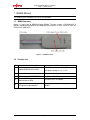
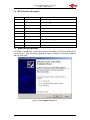
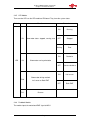
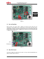
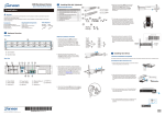
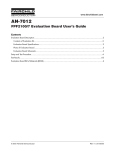
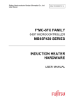
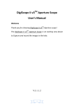
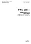
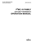
FUJITSU MICROELECTRONICS
SUPPORT SYSTEM
MCU-AN-500070-E-12
F²MC-8FX FAMILY
8-BIT MICROCONTROLLER
MB95330 SERIES
EV BOARD MB2146-440-E
SETUP GUIDE
Starter Kit MB2146-440-E User Manual V1.2
Revision History
Revision History
Date
2009-11-10
2009-11-30
2010-01-12
Author
Kevin Wang
Kevin Wang
Kevin Wang
Change of Records
V1.0, First draft
V1.1,Modify
V1.2,Add speed module
MCU-AN-500070-E-12 – Page 2
EV Board MB2146-440-E Setup Guide
PREFACE
PREFACE
Thank you for purchasing the F2MC-8FX Family EV board: MB2146-440-E.
This product is an EV board for F2MC-8FX MB95330 Series MCU, which comes with MB2146-08-E
(F2MC-8FX Family MB95330 Series BGM Adapter), MB2146-440-E, and F2MC-8L/8FX Family
SOFTUNE Professional Pack Evaluation Version.
This manual explains how to use the EV board. Be sure to read this manual before using the product.
For mass production/evaluation MCUs for this product, consult with sales representatives or support
representatives.
Handling and Use
Handling and use of this product and notes regarding its safe use are described in the manuals for
products bundled with the EV board.
Follow the instructions in the manuals to use this product.
Keep this manual at hand so that you can refer to it anytime during use of this product.
Notice on this Document
All information included in this document is current as of the date it is issued.
Such information is subject to change without any prior notice.
Please confirm the latest relevant information with the sales representatives.
Page 1
EV Board MB2146-440-E Setup Guide
PREFACE
Caution of the Products Described in this Document
The following precautions apply to the product described in this manual.
WARNIN
G
Indicates a potentially hazardous situation which, if not avoided appropriately,
could result in death or serious injury and/or a fault in the user’s system.
performing any operation described in this manual, turn off all the power
Electric shock, Before
supplies to the system. Performing such an operation with the power on may
cause an electric shock or device fault.
Damage
Electric shock, Once the product has been turned on, do not touch any metal part of it. Doing so
may cause an electric shock or device fault.
Damage
CAUTION
Indicates the presence of a hazard that may cause a minor or moderate injury,
damages to this product or devices connected to it, or may cause to lose software
resources and other properties such as data, if the device is not used
appropriately.
Cuts, Damage
Before moving the product, be sure to turn off all the power supplies and unplug
the cables. Watch your step when carrying the product. Do not use the product in
an unstable location such as a place exposed to strong vibration or a sloping
surface. Doing so may cause the product to fall, resulting in an injury or fault.
Cuts
The product contains sharp edges that are left unavoidably exposed, such as
jumper plugs. Handle the product with due care not to get injured with such pointed
parts.
Damage
Do not place anything on the product or expose the product to physical shocks. Do
not carry the product after the power has been turned on. Doing so may cause a
malfunction due to overloading or shock.
Damage
Since the product contains many electronic components, keep it away from direct
sunlight, high temperature, and high humidity to prevent condensation. Do not use
or store the product where it is exposed to much dust or a strong magnetic or
electric field for an extended period of time. Inappropriate operating or storage
environments may cause a fault.
Damage
Use the product within the ranges given in the specifications.
Operation over the specified ranges may cause a fault.
Damage
Damage
To prevent electrostatic breakdown, do not let your finger or other object come into
contact with the metal parts of any of the connectors. Before handling the product,
touch a metal object (such as a door knob) to discharge and any static electricity
from your body.
Before turning the power on, in particular, be sure to finish making all the required
connections. Furthermore, be sure to configure and use the product by following
the instructions given in this document. Using the product incorrectly or
inappropriately may cause a fault.
Damage
Always turn the power off before connecting or disconnecting any cables from the
product. When unplugging a cable, unplug the cable by holding the connector part
without pulling on the cable itself. Pulling the cable itself or bending it may expose
or disconnect the cable core, resulting in a fault.
Damage
Because the structure of the MCU socket does not allow an evaluation MCU to be
mounted in the incorrect orientation, be very careful of the orientation of the
evaluation MCU when mounting it. Inserting the evaluation MCU in the wrong
orientation may damage the MCU, causing the MCU to become faulty.
Damage
Because the product has no casing, it is recommended that it be stored in the
original packaging. Transporting the product may cause a damage or fault.
Therefore, keep the packaging materials and use them in case of for the reshipment of the product.
Page 2
EV Board MB2146-440-E Setup Guide
PREFACE
The contents of this document are subject to change without notice.
Customers are advised to consult with sales representatives before ordering.
The information, such as descriptions of function and application circuit examples, in this document are
presented solely for the purpose of reference to show examples of operations and uses of FUJITSU
MICROELECTRONICS semiconductor device; FUJITSU MICROELECTRONICS does not warrant proper
operation of the device with respect to use based on such information. When you develop equipment
incorporating the device based on such information, you must assume any responsibility arising out of
such use of the information. FUJITSU MICROELECTRONICS assumes no liability for any damages
whatsoever arising out of the use of the information.
Any information in this document, including descriptions of function and schematic diagrams, shall not be
construed as license of the use or exercise of any intellectual property right, such as patent right or
copyright, or any other right of FUJITSU MICROELECTRONICS or any third party or does FUJITSU
MICROELECTRONICS warrant non-infringement of any third-party's intellectual property right or other
right by using such information. FUJITSU MICROELECTRONICS assumes no liability for any
infringement of the intellectual property rights or other rights of third parties which would result from the
use of information contained herein.
The products described in this document are designed, developed and manufactured as contemplated for
general use, including without limitation, ordinary industrial use, general office use, personal use, and
household use, but are not designed, developed and manufactured as contemplated (1) for use
accompanying fatal risks or dangers that, unless extremely high safety is secured, could have a serious
effect to the public, and could lead directly to death, personal injury, severe physical damage or other loss
(i.e., nuclear reaction control in nuclear facility, aircraft flight control, air traffic control, mass transport
control, medical life support system, missile launch control in weapon system), or (2) for use requiring
extremely high reliability (i.e., submersible repeater and artificial satellite). Please note that FUJITSU
MICROELECTRONICS will not be liable against you and/or any third party for any claims or damages
arising in connection with above-mentioned uses of the products.
Any semiconductor devices have an inherent chance of failure. You must protect against injury, damage
or loss from such failures by incorporating safety design measures into your facility and equipment such
as redundancy, fire protection, and prevention of over-current levels and other abnormal operating
conditions.
Exportation/release of any products described in this document may require necessary procedures in
accordance with the regulations of the Foreign Exchange and Foreign Trade Control Law of Japan and/or
US export control laws.
The company names and brand names herein are the trademarks or registered trademarks of their
respective owners.
© 2009 FUJITSU MICROELECTRONICS LIMITED
Page 3
EV Board MB2146-440-E Setup Guide
Contents
Contents
REVISION HISTORY ............................................................................................................ 2
PREFACE ............................................................................................................................. 1
Handling and Use ........................................................................................................ 1
Notice on this Document .............................................................................................. 1
Caution of the Products Described in this Document ................................................... 2
CONTENTS .......................................................................................................................... 4
1
2
3
4
BGMA MANUAL ............................................................................................................ 5
1.1
BGMA Overview ...................................................................................................... 5
1.2
Function List ............................................................................................................ 5
1.3
IDC10 Interface Description .................................................................................... 6
1.4
BGMA USB Configuration ....................................................................................... 6
1.5
LED Description ...................................................................................................... 8
EV BOARD INTRODUCTION ...................................................................................... 10
2.1
EV Board Overview ............................................................................................... 10
2.2
Function List .......................................................................................................... 11
2.3
EV Board Schematic ............................................................................................. 12
2.4
HW Module Description ......................................................................................... 13
2.4.1
Power Module .......................................................................................... 13
2.4.2
BGMA Interface ....................................................................................... 13
2.4.3
Key Module.............................................................................................. 13
2.4.4
Speed Module ......................................................................................... 13
2.4.5
LED Module ............................................................................................. 14
2.4.6
Feedback Module .................................................................................... 14
2.4.7
Motor Drive Module ................................................................................. 15
EV BOARD OPERATION ............................................................................................ 16
3.1
Connect the Motor Connector and the Hall Sensor Connector .............................. 16
3.2
Select the Driving Method as Hall Sensor or Back EMF ........................................ 16
3.3
Start and Stop Motor ............................................................................................. 17
3.4
Adjust Motor Speed ............................................................................................... 17
3.5
Reverse Motor Rotation......................................................................................... 18
DEVELOPMENT PLATFORM QUICK START ............................................................ 19
4.1
Tools Setup Sequence .......................................................................................... 19
4.2
Open Project and Start Debug............................................................................... 19
Page 4
EV Board MB2146-440-E Setup Guide
Chapter 1 BGMA Manual
1 BGMA Manual
This chapter gives introduction on how to set up BGMA.
1.1
BGMA Overview
Below is a close look of MB95330 Series BGMA. The part number is MB2146-08-E. It
provides a debugging platform for the MB95330 Series MCU in a small size of 55.7mm (W)
X127mm (D) X30mm (H).
Figure 1.1-1 BGMA overview
1.2
Function List
ID
Function description
Remarks
1
Support MB95330 Series MCU
2
Break pointer
256 software breakpoints
3
USB interface to PC/SOFTUNE
Compatible with USB protocol version 1.1
4
1-Line UART interface to the
MB95330 Series MCU
The Baud rate is 62,500 bps
5
Support the MCU flash programming The programming and reading speed is about
for engineering development
800 B/S.
MCU MAX machine clock: 16.25 MHz
MCU power voltage: 2.4 V ~ 5.5 V
Page 5
EV Board MB2146-440-E Setup Guide
Chapter 1 BGMA Manual
1.3
IDC10 Interface Description
Pin Number
1.4
Pin Name
Description
1
UVCC
Target MCU VCC
2
GND
Target MCU VSS
3
RSTIN
Target MCU reset input
4
RSTOUT
Target MCU reset output
5
RSV
Reserved
6
RSV
Reserved
7
RSV
Reserved
8
DBG
Target MCU debugging pin
9
RSV
Reserved
10
RSV
Reserved
BGMA USB Configuration
The BGMA is provided with a USB cable. Connect the BGMA to PC with the USB cable. If
the connection is right, the following window will pop up. Follow the instructions displayed,
and then click “Next”.
Figure 1.3-1 Install BGMA in Windows (1)
Page 6
EV Board MB2146-440-E Setup Guide
Chapter 1 BGMA Manual
Select “Install from a list or specific location (Advanced)”, then click “Next”.
Figure 1.3-2 Install BGMA in Windows (2)
Select “…\Drivers” from the folder where SOFTUNE is installed, click “Next”.
Figure 1.3-3 Install BGMA in Windows (3)
Page 7
EV Board MB2146-440-E Setup Guide
Chapter 1 BGMA Manual
Select “BGMA (MB2146-08)” as displayed below, and then click “Next”.
Figure 1.3-4 Install BGMA in Windows (4)
Windows will install the driver automatically. Click “Finish” after the driver has completed the
installation normally. Then users can find the BGMA is recognized as MB2146-08 in
Windows system.
Figure 1.3-5 BGMA is installed in Windows
1.5
LED Description
First, only plug USB cable to PC; check whether the power LED on BGMA turns green.
Refer to Figure 1.4-1.
Green
USB Plugged to PC
Figure 1.4-1 BGMA Power LED (1)
Page 8
EV Board MB2146-440-E Setup Guide
Chapter 1 BGMA Manual
Second, plug IDC10 cable to the EV board (target MCU board), then turn on EV board. After
that, check whether the power LED on the BGMA turns orange. Refer to Figure 1.4-2.
Orange
Figure 1.4-2 BGMA Power LED (2)
Page 9
EV Board MB2146-440-E Setup Guide
Chapter 2 EV Board Introduction
2 EV Board Introduction
2.1
EV Board Overview
MB95330 Series EV board provides a user-friendly evaluation platform for the MB95330
Family microcontroller.
MB95330H/330K MCU EV board PN is MB2146-440-E.
Figure 2.1 is a close look of EV board.
Debug Interface
Power circuit
Motor driver circuit
Test pin
LED
Potentiometer
Motor
Key
Feedback interface
Figure 2.1 EV board Overview
Page 10
EV Board MB2146-440-E Setup Guide
Chapter 2 EV Board Introduction
2.2
Function List
This MB95330 Motor EV board provides a platform with inverter motor circuit, for user to
evaluate MB95330 series MCU and demo 120 degree inverter driving solution together with
sample code. It features the following functions,
Provide IDC10 debug interface
All MCU ports are easy accessible through test pins
Support 120 degree inverter driving solution, hall sensor or back-EMF
Support motor start, motor stop, speed increase, speed decrease, reverse.
Page 11
EV Board MB2146-440-E Setup Guide
Chapter 2 EV Board Introduction
2.3
EV Board Schematic
Page 12
EV Board MB2146-440-E Setup Guide
Chapter 2 EV Board Introduction
2.4
HW Module Description
2.4.1
Power Module
Input DC 15V from outside, supply it to motor driver circuit and motor directly, and convert it
to 5V for MCU. Please read the following instructions before using.
DC Adaptor: 15V DC
Output voltage: 15V
Output Current: 2A
Connection: Power connector (DC 15V)
2.4.2
BGMA Interface
To start debugging using a BGMA, users can connect IDC10 socket from the BGMA to
BGMA IF on an EV board before power on.
2.4.3
Key Module
The key module controls motor start, stop, reverse.
Module
name
Function
START/STOP
Motor start and motor stop
REVERSE
Clockwise/Counter clockwise
HALL SENSOR/SENSOR LESS
Select motor driving method
SW1
Reserve
Key
2.4.4 Speed Module
Module
name
Speed up/down
R59
Function
Speed down: Tune clockwise;
Speed up: Tune anticlockwise.
Page 13
EV Board MB2146-440-E Setup Guide
Chapter 2 EV Board Introduction
2.4.5
LED Module
There are four LEDs on the LED module of EV board. They show the system status.
Module name
D8
LED
D9
Function
Show motor status: stopped, running, error
ON
Running
OFF
Stopped
Winking
Error
ON
Clockwise
OFF
Counter clockwise
ON
Hall sensor
OFF
Back EMF
Show motor running orientation
D10
D11
2.4.6
Remark
Show motor driving method:
hall sensor or Back EMF
Reserve
Feedback Module
The module inputs the motor back EMF signal to MCU.
Page 14
EV Board MB2146-440-E Setup Guide
Chapter 2 EV Board Introduction
2.4.7
Motor Drive Module
The module is designed for driving motor. It features the following functions:
250V 3.0A 3-phase FRFET inverter including high voltage integrated circuit (HVIC);
HVIC for gate driving and under voltage protection;
Optimized for low electromagnetic interference;
Isolation voltage rating of 1500Vrms for 1min.
Page 15
EV Board MB2146-440-E Setup Guide
Chapter 3 EV Board Operation
3 EV Board Operation
3.1
Connect the Motor Connector and the Hall Sensor Connector
Before power on, connect the motor lines to the motor connector and the hall sensor
connector according to the following direction. Refer to Figure 3.1.
Note: If the driving method is Back EMF, the hall sensor connector should not be connected.
W
V
U
Motor connector
GND
H3
H2
Hall sensor connector
H1
5V
Figure 3.1
3.2
Select the Driving Method as Hall Sensor or Back EMF
If you want to select the hall sensor, the switchers are set as J1(2-3),J2(2-3), and J3(2-3).
Otherwise, the switchers are set as J1(1-3),J2(1-3), and J3(1-3). Switch on the power and
the power LED turns on. When the LED3 is on, it means the FW driving method is B-EMF. If
you want to change the FW driving method, press the hall sensor/B-EMF key when the
motor is stopped. Then, the LED3 turns off. It means the FW driving method is hall sensor.
Refer to Figure 3.2.
Notes: The selection of the FW driving method should match with the selection of switchers.
Page 16
EV Board MB2146-440-E Setup Guide
Chapter 3 EV Board Operation
1
2
3
J1
J2
J3
Hall sensor/B-EMF Key LED3
Figure 3.2
3.3
Start and Stop Motor
When the LED1 is off, it means motor is stopped. If you want to start the motor, press the
start/stop key, and the LED1 turns on. It means motor is running. At the same time, you can
see that motor is rotating. If you want to stop the motor, press the start/stop key again, and
the LED1 turns off. It means motor is stopped. At the same time, you can see that the motor
is stopped. Refer to Figure 3.3.
LED1
Start/stop key
Figure 3.3
3.4
Adjust Motor Speed
If you want to adjust the speed when the motor is running, tuning the potentiometer can
adjust the speed. Refer to Figure 3.4.
Page 17
EV Board MB2146-440-E Setup Guide
Chapter 3 EV Board Operation
Potentiometer
Figure 3.4
3.5
Reverse Motor Rotation
Pressing the reverse key can reverse motor rotation when the motor is stopped. The on and
off of LED2 respectively indicate clockwise and counter clockwise. Refer to Figure 3.5.
LED2
Reverse key
Figure 3.5
Page 18
EV Board MB2146-440-E Setup Guide
Chapter 4 Development Platform Quick Start
4 Development Platform Quick Start
4.1
Tools Setup Sequence
Start the debugging system in the following sequence:
Connect a BGMA to the PC using a USB cable, confirm the LED on the BGMA is green;
Connect an EV board to BGMA IF socket;
Turn on the EV board, confirm the LED on the BGMA is orange and the power LED on
the EV board is on.
4.2
Open Project and Start Debug
Users can start a debugging from PC software SOFTUNE workbench in the following
sequence.
Start the SOFTUNE from “Startup Menu>Programs> SOFTUNE V3> FFMC-8L Family
SOFTUNE Workbench” in Windows;
Click “Open workspace” from “File” Menu in SOFTUNE;
Select “MB95F334 Motor Drive V1.0.prj” in “Open Space” window;
Click “Start debug” from “Debug” Menu.
If the entire procedure goes right, a debugging will start normally.
Page 19
MCU-AN-500070-E-12
FUJITSU MICROELECTRONICS LIMITED • SUPPORT SYSTEM
F2MC-8FX Family MB95330 Series
MB2146-440-E
SETUP GUIDE
Nov. 2009 the first edition
Published FUJITSU MICROELECTRONICS LIMITED