1
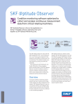
SKF Multilog On-line
System WVT
CMWA 7910
Cost effective, reliable and secure wireless condition
monitoring for semi-critical and balance-of-plant
machinery
Introduction
The SKF Multilog On-line System WVT is an
advanced field mounted monitoring device
that uses the Honeywell OneWireless Network. Machine condition data is uploaded to
the Honeywell Experion Process Knowledge
System (PKS) for trending and viewing on
operator screens. Conformance with the
ISA100.11a wireless standard provides reliable and encrypted data transmission.
Ideally suited for:
• Hazardous and non-hazardous areas
• Supplementing walk-around routes
• Machines that:
–– Traverse / move
–– Are distressed and require analysis
One SKF Multilog WVT typically covers the
monitoring requirements of a single
machine train, providing vibration and temperature data from both the driver and the
driven machine. The data includes information associated with machine installation
and foundation, rotor systems, and bearings
as well as process related issues that can
impact machinery performance or lead to
reduced service life.
Key features
• Long battery life – up to 5 years, or external DC powered
• Over 40 static and dynamic measurements available per device, including
acceleration, velocity, SKF Acceleration
Enveloping (bearing condition), temperature and speed
• LCD display shows latest overall measurements, next trend and trace sample
time, radio strength, battery status
• Detailed data analysis available with
SKF @ptitude Analyst software
• Utilizes mesh networking technology
Built by two industry leaders, SKF and Honeywell, the SKF Multilog WVT is cost efficient technology designed to support
increased machine uptime, reduced maintenance and improved safety. The seamless
integration into your existing OneWireless
infrastructure accelerates implementation
and helps to reduce costs.
System components
SKF and Honeywell components that make
up a monitoring system:
• SKF Multilog On-line System WVT
• SKF Sensors and cables
• Data Controller software
• SKF @ptitude Analyst software for additional data analysis
(optional)
• Honeywell Field Device Access Point (FDAP)*
• Honeywell Wireless Device Manager (WDM)*
• Honeywell Experion Process Knowledge System (PKS)*
How does it work?
The SKF Multilog WVT sends machine condition data to the Honeywell Field Device Access Point (FDAP), which transfers the data to the
Honeywell Wireless Device Manager. The Wireless Device Manager
hosts the gateway, system manager and security manager components. From there, the data is sent to the Experion Process Knowledge System as well as SKF @ptitude Analyst software.
*Purchase separately from Honeywell
System components: hardware and basic network
Experion
station
SKF Multilog
On-line
System WVT
Dual data paths
Field device
access point
Wireless device manager
SKF acceleration and
temperature sensors
Data Controller software (required)
and SKF @ptitude Analyst software
(optional)
2
Dual data paths
The SKF Multilog WVT machinery condition data is automatically
uploaded to the Honeywell Experion Process Knowledge System.
This same data also forms part of a more comprehensive data set
that can be transmitted to the SKF @ptitude Analyst software. Data
can also be exported using MODBUS and OPC.
• SKF @ptitude Analyst software offers a completely integrated
approach to condition monitoring by accepting data from the full
range of SKF data collection devices. Detailed information is efficiently organized so automated reports can deliver the level of
information you specify.
• Honeywell’s Experion Process Knowledge System is used in
industrial plants and mills to integrate, control and monitor complex processes in many types of industrial settings.
Data viewing, analysis
and reporting in
SKF @ptitude Analyst.
Honeywell’s Wireless Device Manager (WDM) software.
3
Specifications
SKF Multilog On-line System WVT
Measurement
Dual input channels (1 to 4)
• Number of channels: 4 x dual input,
vibration and temperature
• Sensor type: Accelerometer, special low
power (<300 µW per channel)
• Coupling: DC
• Accelerometer power: 3,3 V DC
• Input voltage range: ±1,25 V around 1,5 V
bias
• Nominal sensitivity: 50 mV/g
• Amplitude range: ±25 g
• Measurements: Acceleration, enveloped
acceleration, velocity (by software integration)
• Gain ranges: 2 gain steps of 1 and 10
with clip detect
• Amplitude accuracy: ±2% typical in passband
• Dynamic range: > 70 dB
• Bias voltage check: Programmable interval
Temperature input
• Input voltage range: 0,25 to 2,75 V
• Sensitivity: –10,9 mV/°C (–6.06 mV/°F)
• Temperature measurement range: –40 to
+120 °C (–40 to +248 °F)
• Accuracy: ±2,5 °C (±4.5 °F) typical
Processing
• Bandwidth ranges: (0,5 to 100 Hz) to
(0,5 Hz to 20 kHz) (Fmax in 1, 2, 5 steps)
• Data block lengths: 256 to 8 192
• Spectral lines: 100 to 3 200
• Integration: One level in software
• Bearing demodulation: Hardware demodulator, fixed bandpass 500 Hz to 10 kHz
(SKF Acceleration Enveloping filter 3)
• Averages: 1 to 4, 50% overlap, spectral
domain only
• Non-volatile RAM: 512 kB
• Internal real-time clock
Tachometer
• Number of channels: One digital isolated
or NAMUR
• Digital isolated trigger levels: Logic lo
<0,7 V, logic hi 4,5 to 24,0 V
• NAMUR type: Two-wire low power
• Maximum frequency: 10 kHz
Interfaces
• Visual display: 21 character x 7 line LCD
display, backlit with auto-shutdown
• Local pushbutton: Allows local interrogation of measurements, radio status, network, battery status
• Configuration interface: Infrared
(ISA100.11a provisioning interface)
Communications
• Network: 802.15.4, ISA100.11a compatible
• Cable: USB port for diagnostics
• Programming: Firmware upgrades over
radio network or USB
Radio
• Network: 2,4 GHz, IEEE 802.15.4
• Firmware upgrade: Over-the-Air-Provisioning (OTAP)
• Encryption: 128 bit AES
• Power / range
–– FCC/IC (USA) Radio +11 dBm, antenna
5 dBi/range 300 meters (984 feet)
–– ETSI (Europe) Radio +4 dBm, antenna
5 dBi/range 100 meters (328 feet)
Mechanical
• Enclosure: Cast aluminum, painted
• Dimensions: 26 × 16 × 9 cm (10.2 × 6.3 ×
3.5 in.)
• Weight: 2,8 kg (6.2 lbs.)
• Cable entries: 6 glands
• Cable diameter: 3,0 to 6,5 mm (0.12 to
0.26 in.)
Environmental
• Operating temperature: –30 to +75 °C
(–20 to +167 °F)
• Sealing: IP 66
• Compliance: CE, RoHS
• Hazardous locations:
–– CSA Class 1, Division 2, Groups A, B, C,
D
–– ATEX (certification pending)
Power
• Input power: Battery or DC power (10 to
30 V DC)
• Battery type: 2 x lithium 3,6 V, D cell, type
Xeno XL-205F
• Battery monitor: Internal battery monitor
and critical battery shutdown
• Isolation: 1 500 V from DC power input
• Battery life: Up to 5 years with default
measurement configuration (refer to
Table 1)
– NOTE 1: Battery life is dependent on multiple operating parameters including, measurement settings, usage and ambient temperature.
– NOTE 2: Continuous operation at the extreme
ends of the ambient operating temperature range, high and low, will significantly
shorten battery life.
– NOTE 3: Configuring a device for routing mode requires connection to a permanent power
source.
Table 1
Battery life (example configurations using all four channels)
4
Battery life expectancy
Monthly
Daily
Hourly
Up to 5 years
• Time waveform
• Velocity spectrum
• Acceleration Enveloping (gE) spectrum
• Bias voltage check
• Overall velocity
• Overall Acceleration Enveloping (gE)
• Temperature
• Speed (with recommended Tachometer)
SKF Multilog WVT Dimensions
2,5 cm
(1.0 in.)
35,5 cm
(12.0 in.)
1,5 cm
(0.6 in.)
2,0 cm
(0.8 in.)
2,0 cm
(0.8 in.)
Important Safety Information
for Hazardous Locations
16,0 cm
(6.3 in.)
802.15 ISA100
NORTH AMERICAN AREAS:
When providing circuits to Zone 1, the unit must
be powered from internal batteries using ia or ib
sensors. When providing circuits to Zone 2, the
unit may be powered externally using ia, ib or nL
sensors, or from batteries using ia or ib sensors.
WARNING - EXPLOSION HAZARD!
Batteries must only be changed in an area known
to be non-hazardous.
AVERTISSEMENT - RISQUE D’EXPLOSION Afin d’eviter tout risqué d’explosion, s’assurer que
l’emplacement est designe non dangereux avant
d’ouvrir le couvercle du boitier.
Battery Type: Xeno XL-205F or equivalent (x2)
External Power: 10-30Vdc
20,0 cm
(7.9 in.)
SKF Multilog On-line System WVT
CMWA 7910
26,0 cm
(10.2 in.)
9,0 cm
(3.5 in.)
5
CMSS 2350T-D2
Agency approved low powered industrial sensor,
acceleration and temperature, straight exit
The CMSS 2350T-D2 is a low powered, dual output sensor
designed for use with the SKF Multilog WVT, CMWA 7910 device.
Together, the system forms a solution for permanent wireless vibration monitoring.
Common applications include rotating machinery such as pumps,
motors and fans.
Features
• For use with the SKF Multilog WVT, CMWA 7910 device
• M12 connector
• Rugged, corrosion resistant and hermetically sealed
• Case isolated
• Low power
• Non-incendive
Specifications
Dynamic
• Sensitivity, 25 °C (77 °F): 50 mV/g
• Sensitivity precision: ±5%
• Acceleration range: 25 g peak
• Amplitude non-linearity: 1%
• Frequency range, ±3 dB: 0,3 to 15 000 Hz
• Resonance frequency, nominal: 30 kHz
• Transverse sensitivity: ≤ 5% of axial
• Temperature response: ±10% sensitivity, –25 to +120 °C (–15 to
+248 °F)
• Temperature sensitivity: –10,9 mV/°C (–6.06 mV/°F)
Typical temperature response
Deviation, % sensitivity
Deviation, dB
3
+10
2
1
0
0
–1
–10
6
• Power requirements:
–– Voltage source: 3 to 5,5 V
–– Current consumption: < 100 µA
• Electrical noise, equivalent g:
–– Broadband:
·· 2,5 Hz to 25 kHz: 660 µg
–– Spectral:
·· 10 Hz: 60 µg/√Hz maximum
·· 100 Hz: 16 µg/√Hz maximum
·· 1 000 Hz: 5 µg/√Hz maximum
• Output impedance: < 1 000 Ω
• Bias output voltage (BOV): 1,5 V, ±5%
• Bias output voltage stability, including temperature effects:
1,5 V DC, ±5%
• Grounding: Case isolated, internally shielded
Typical frequency response
+20
–20
–25
(–15)
Electrical
–2
0
(+30)
+25
(+75)
+50
(+120)
+75
(+170)
+100
+120
(+210) (+250)
Temperature, °C (°F)
–3
0.3
1
10
100
1k
10 k
Frequency, Hz
Environmental
• Temperature range: –40 to +120 °C (–40 to +250 °F) operating
temperature
• Vibration limit: 500 g peak
• Shock limit: 5 000 g peak
• Sealing: Hermetic
• Base strain sensitivity, maximum: 200 µg/µstrain
CMSS 2350T-D2 Dimensions
21,8 mm
(0.86 in.)
M12 four-pin
connector
Physical
• Dimensions: See drawing
• Weight: 90 g (3.2 oz.)
• Case material: 316L stainless steel
• Mounting:
–– Internal 1/4-28 thread
–– 1/4-28 to 1/4-28 mounting stud and 1/4-28 to M8 mounting
adapter provided
• Mounting torque: 2,9 Nm (24 in. lbs.)
• Connections: 4-pin M8 connector
–– Pin 1: Power (red)
–– Pin 2: Common (black)
–– Pin 3: Signal, acceleration (1,5 V BOV) (white)
–– Pin 4: Signal, temperature (green)
• Mating connector: M12 style, 4-pin
47,0 mm
(1.85 in.)
MODEL CMSS2350T-D2
S/N S00000
1/4-28
to M8
mounting stud
OR
1/4-28 to 1/4-28
mounting stud
19,0 mm
(0.75 in.)
21,2 mm
(0.87 in.)
across flats
Agency approvals
• ATEX Zone 2, 3 G, Ex nA nC IIC T5 Gc, Ta = –50 °C to +85 °C.
• CSA
–– Class I, Division 2, Groups A, B, C, D
–– Class II, Division 2, Groups E, F, G
–– Class III, T5 Ex nL IIC; T5
• CE approved
4
1
3
Connector key
2
CMAC 2350-CABLE-xx
Agency approved cable assembly for the
CMSS 2350T-D2 sensor
Cable assembly
• Connector: Five (5) socket M12 connector
• Ingress protection rating: IP 67
• Strain relief material: Fluoroelastomer
terpolymer
• Cable: Four (4) conductor cable
• Cable Jacket: FEP (Fluorinated ethylene
propylene)
• Color: Grey
• Shielded: Single shield
• Dimensions (diameter): 4.88 mm
(0.188 in.)
• Compliant: RoHS compliant
• Operating temperature range: –60 to
+200 °C (–76 to +392 °F)
Connector view
3
5
4
2
Keyway
1
Function
Cable
1
Power
Red
2
Common
Black
3
Acceleration signal out
White
4
Temperature signal out
Green
5
Connector shell
N/C
7
CMCP WVT-PWR-SUP
Agency approved power supply for up to four
SKF Multilog WVT – CMWA 7910
Enclosure Material
• Non-metallic enclosure
• Solid body and cover
–– PBT/PC blended plastic
–– UL94-5VA flammability rating
–– UV stabilized
Enclosure ratings
• UL508 Type 1, 2, 4, 4X, 12 and 13
• NEMA Type 1, 2, 4, 4X, 12 and 13
• IEC529-IP65
Dimensions
280 mm
(11.024 in.)
190 mm
(7.485 in.)
8
130 mm
(5.111 in.)
Specifications
Input
• Nominal input voltage range: 100 to 240 V AC
• Input voltage range: 85 to 264 V AC
• AC frequency range: 45 to 65 Hz
• Current consumption: 0.75 A (120 V AC) / 0.45 A (230 V AC)
• In-rush surge current: <15 A (typical)
• Power failure bypass: >35 ms (120 VA C), >150 ms (230 V AC)
• Input fuse: 3.15 A (slow-blow, internal)
• Nominal output voltage: 24 V DC ±1%
Output
• Output voltage: 24 V DC
• Output current:
–– 1.5 A (–25 to +60 °C) / 2 A (–25 to +40 °C)
–– 1.5 A (–13 to +140 °F) / 2 A (–13 to +104 °F)
• Derating: 60 to 70 °C (140 °F to 158 °F), 2.5%/K
• Connection in parallel: yes, for redundancy and increased capacity
• Connection in series: yes
• Residual ripple: >40 mVPP (with nominal values)
• Peak switching voltages, nominal load: <20 mVPP (20 MHz)
• Maximum power dissipation, no-load: 1.5 W
• Power loss, nominal load: Maximum 6.5 W
Hazardous area approvals
• ATEX II 3 G Ex nA nC IIC T4 Gc X
• CSA/UL: 22.2 Class I Division 2
• Other: UL/C-UL Listed UL 508
Temperature ratings
• Ambient temperature (operation):
–– –25 to +70 °C <> 60 °C (derating)
–– –13 to +158 °F <> 140 °F (derating)
• Ambient temperature (storage / transport): –40 to +85 °C
(–40 to +185 °F)
• Maximum permissible relative humidity (operation): 100% (condensation permitted)
9
Ordering information
Bundles
Accessories and additional components
SKF Multilog WVT – North American telecom standard*
• CMWA 7910-FCC/IC, SKF Multilog WVT
Starter kit - North American telecom standard
SKF Multilog WVT – European telecom standard*
• CMWA 7910-SK-5M-FCC/IC*
–– One (1) each, CMWA 7910-FCC/IC, SKF Multilog WVT
–– Four (4) each, CMSS 2350T-D2, low power industrial sensors
–– Four (4) each, CMAC 2350-CABLE-5M, 5 m (16.4 ft.) cable
assemblies
–– CMSW 7915, Data Controller software
–– Product reference CD, with user manual
• CMWA 7910-SK-10M-FCC/IC*
–– One (1) each, CMWA 7910-FCC/IC, SKF Multilog WVT
–– Four (4) each, CMSS 2350T-D2, low power industrial sensors
–– Four (4) each, CMAC 2350-CABLE-10M, 10 m (32.8 ft.) cable
assemblies
–– CMSW 7915, Data Controller software
–– Product reference CD, with user manual
• CMWA 7910-ETSI, SKF Multilog WVT
Starter kit - European telecom standard
• CMWA 7910-SK-5M-ETSI*
–– One (1) each, CMWA 7910-ETSI, SKF Multilog WVT
–– Four (4) each, CMSS 2350T-D2 low power industrial sensors
–– Four (4) each, CMAC 2350-CABLE-5M, 5 m (16.4 ft.) cable
assemblies
–– CMSW 7915, Data Controller software
–– Product reference CD, with user manual
• CMWA 7910-SK-10M-ETSI*
–– One (1) each, CMWA 7910-ETSI, SKF Multilog WVT
–– Four (4) each, CMSS 2350T-D2 low power industrial sensors
–– Four (4) each, CMAC 2350-CABLE-10M, 10 m (32.8 ft.) cable
assemblies
–– CMSW 7915, Data Controller software
–– Product reference CD, with user manual
*Battery not included in the SKF Multilog WVT and should be ordered separately as
shown to the right or sourced locally.
10
Battery
• CMAC 7910-BAT-02, battery (set of 2), lithium 3.6 V, D cell, type
Xeno XL-205F
WARNING:The cover on the enclosure can be removed for batteries changing
or other servicing only in an area known to be non-hazardous.
Battery holder
• CMAC 7910-BH, battery holder, includes battery cradle mounted
on PC board with integral connector
Power supply
• CMCP WVT-PWR-SUP, power supply in fiberglass enclosure,
IP 66, CUL-EX Cl1/Division 2 Groups A, B, C, D
Vibration / temperature sensor
• CMSS 2350T-D2, low power industrial sensor
Cable assemblies for vibration / temperature sensor
• CMAC 2350-CABLE-5M, 5 m (16.4 ft.) cable with M12 4-pin,
connector
• CMAC 2350-CABLE-10M, 10 m (32.8 ft.) cable with M12 4-pin,
connector
• CMAC 2350-CABLE-20M, 20 m (65.6 ft.) cable with M12 4-pin,
connector
Software
• CMSW 7915, Data Controller software**
• CMSW 7400-SC-SL, SKF @ptitude Analyst Software, single client
** Data Controller software
•• Communicates with a maximum of eight wireless device managers.
•• Communicates with a maximum of 240 SKF Multilog WVT devices (up to 30 SKF
Multilog WVT devices per Wireless device manager).
•• Configures SKF Multilog WVT devices from default factory state to user-provided configuration data.
•• Collects time wave, spectrum data, and trend values (or process value, PV) from all
four channels of SKF Multilog WVT devices at user-configured periods for these possible measurements: acceleration, velocity and bearing, speed, bias voltage and temperature.
•• Provides the collected time wave, spectrum data and trend values to SKF @ptitude
Analyst software for additional data analysis.
Accessories and additional components (continued)
Remote antenna installation accessories
• CMAC 7820-ANT, Antenna (Spare)
• CMAC 7820-MK, Remote antenna mounting kit
• CMAC 7820-EXTCBL-1M, 1 m (3.3 ft.) cable for remote antenna
• CMAC 7820-EXTCBL-3M, 3 m (9.8 ft.) cable for remote antenna
• CMAC 7820-EXTCBL-10M, 10 m (32.8 ft.) cable for remote
antenna
Support services
SKF offers a wide range of on-site technical services including:
• System installation services – commissioning, testing, reporting
• Sensor mounting, installation or verification
• Vibration analysis by SKF Reliability experts
• Product and technology specific training through SKF Reliability
Maintenance Institute
NOTE: One (1) CMAC 7820-ANT is supplied with each SKF Multilog WVT. For remote
antenna installation choose one (1) cable assembly from the above list and one
(1) mounting kit.
Tachometer and tachometer cable assemblies
• CMAC 7911, agency approved tachometer sensor, NAMUR
standard, 8 mm tip diameter, M8 thread
• CMAC 7911-CABLE-5M, 5 m (16.4 ft.) cable with M12 4-pin,
connector
• CMAC 7911-CABLE-10M, 10 m (32.8 ft.) cable with M12 4-pin,
connector
• CMAC 7911-CABLE-25M, 25 m (82.0 ft.) cable with M12 4-pin,
connector
11
The Power of Knowledge Engineering
Combining products, people, and applicationspecific knowledge, SKF delivers innovative
solutions to equipment manufacturers and production facilities in every major industry worldwide. Having expertise in multiple competence
areas supports SKF Life Cycle Management, a
proven approach to improving equipment reliability, optimizing operational and energy efficiency
and reducing total cost of ownership.
These competence areas include bearings and
units, seals, lubrication systems, mechatronics,
and a wide range of services, from 3-D computer
modelling to cloud-based condition monitoring
and asset management services.
SKF’s global footprint provides SKF customers
with uniform quality standards and worldwide
product availability. Our local presence provides
direct access to the experience, knowledge and
ingenuity of SKF people.
SKF BeyondZero is more than our climate strategy
for a sustainable environment: it is our mantra; a
way of thinking, innovating and acting.
For us, SKF BeyondZero means that we will
SKF USA Inc.
reduce the negative environmental impact from
Condition Monitoring Center – San Diego
own operations and at the same time, increase
5271 Viewridge Court · San Diego, California 92123ourUSA
Tel: +1 858-496-3400 · Fax: +1 858 496-3531 the positive environmental contribution by offering
Web: www.skf.com/cm
our customers the SKF BeyondZero portfolio of
products and services with enhanced environmental performance characteristics.
For inclusion in the SKF BeyondZero portfolio,
a product, service or solution must deliver significant environmental benefits without serious
environmental trade-offs.
Bearings and
housings
Seals
Mechatronics
Lubrication
systems
Services
Please contact:
®SKF, @PTITUDE and MULTILOG are registered trademarks of the SKF Group.
Honeywell and OneWireless are trademarks of Honeywell International Inc.
All other trademarks are the property of their respective owners.
©SKF Group 2015
The contents of this publication are the copyright of the publisher and may not be reproduced (even
extracts) unless prior written permission is granted. Every care has been taken to ensure the accuracy
of the information contained in this publication but no liability can be accepted for any loss or damage
whether direct, indirect or consequential arising out of the use of the information contained herein.
SKF reserves the right to alter any part of this publication without prior notice.
Patents: US 4,768,380 · US 5,633,811 · US 5,679,900 · US 5,845,230 · US 5,852,351 · US 5,854,553 · US 5,854,994 · US 5,870,699 · US 5,907,491 · US 5,992,237 · US 6,006,164 · US 6,124,692 · US 6,138,078 · US 6,199,422 · US 6,202,491 · US 6,275,781 · US 6,301,514 · US 6,437,692 · US 6,489,884 · US 6,513,386 · US 6,633,822 · US 6,789,025 · US 6,792,360 · US 7,103,511 · US 7,697,492 · WO/2003/048714
PUB CM/P8 14136 EN · June 2015
skf.com