1
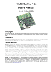
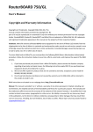
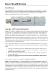
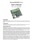
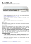
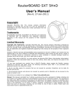
RouterBOARD 1100
User's Manual
Copyright and Warranty Information
Copyright and Trademarks. Copyright MikroTikls SIA. This manual contains information protected by
copyright law. No part of it may be reproduced or transmitted in any form without prior written permission
from the copyright holder. RouterBOARD, RouterOS, RouterBOOT and MikroTik are trademarks of MikroTikls
SIA. All trademarks and registered trademarks appearing in this manual are the property of their respective
holders.
Hardware. MikroTik warrants all RouterBOARD series equipment for the term of fifteen (15)
months from the shipping date to be free of defects in materials and workmanship under normal
use and service, except in case of damage caused by mechanical, electrical or other accidental or
intended damages caused by improper use or due to wind, rain, fire or other acts of nature.
To return failed units to MikroTik, you must perform the following RMA (Return Merchandise
Authorization) procedure. Follow the instructions below to save time, efforts, avoid costs, and
improve the speed of the RMA process.
1.If you have purchased your product from a MikroTik Reseller, please contact the Reseller
company regarding all warranty and repair issues, the following instructions apply ONLY if you
purchased your equipment directly from MikroTik in Latvia.
2. We do not offer repairs for products that are not covered by warranty. Exceptions can be made
for RB1000 and RB1100.
3. Out-of-warranty devices and devices not covered by warranty sent to Mikrotikls will be
returned to the sender at sender's cost.
RMA Instructions are located on our webpage here: http://rma.mikrotik.com
Manual. This manual is provided “as is” without a warranty of any kind, expressed or implied,
including, but not limited to, the implied warranty of merchantability and fitness for a particular
purpose. The manufacturer has made every effort to ensure the accuracy of the contents of this
manual, however, it is possible that it may contain technical inaccuracies, typographical or other
errors. No liability is assumed for any inaccuracy found in this publication, nor for direct or
indirect, incidental, consequential or other damages that may result from such an inaccuracy,
including, but not limited to, loss of data or profits. Please report any inaccuracies found to
[email protected]
RouterBOARD 1100 Series User's Manual
Table of Contents
Copyright and Warranty Information
.................................................................................................................................................... 1
System Board View and Layout.........................................................................................................3
Specifications................................................................................................................4
Hardware Guide.............................................................................................................................. 4
Memory and Storage Devices...................................................................................................4
Memory........................................................................................................................4
Storage Device..............................................................................................................4
microSD slot.................................................................................................................4
Input/Output Ports..................................................................................................................4
Ethernet ports...............................................................................................................4
Ethernet bypass mode....................................................................................................5
DB9 Serial Port..............................................................................................................5
Fan Connectors..............................................................................................................5
LEDs..................................................................................................................................... 5
Power LED....................................................................................................................5
User LED......................................................................................................................5
User's Guide................................................................................................................................... 5
Assembling the Hardware........................................................................................................5
Powering............................................................................................................................... 5
Booting options......................................................................................................................5
Onboard NAND Storage Device........................................................................................6
Internal Storage Device..................................................................................................6
Booting from network.....................................................................................................6
Operating System Support.......................................................................................................6
MikroTik RouterOS.........................................................................................................6
RouterBOOT................................................................................................................................... 6
Boot Loader Configuration........................................................................................................6
Configurable Options......................................................................................................7
Boot Loader Upgrading............................................................................................................7
Primary Boot Loader...............................................................................................................8
RouterOS on RouterBOARD 1100.......................................................................................................8
Health monitor.......................................................................................................................8
Firmware information..............................................................................................................8
Firmware Settings..................................................................................................................8
Software Reset.......................................................................................................................8
Appendix....................................................................................................................................... 9
Connector Index.....................................................................................................................9
Button Index..........................................................................................................................9
Ethernet Cables......................................................................................................................9
Serial Null-modem (Console) Cable with Loopback.......................................................................9
2
RouterBOARD 1100 Series User's Manual
System Board View and Layout
You can download the board dimensions and case design files (PDF and DXF) from www.routerboard.com
3
RouterBOARD 1100 Series User's Manual
Specifications
RouterBOARD 1100
CPU
MPC8544 800MHz network processor
Memory
SODIMM slot, no onboard module
Boot loader
RouterBOOT
Data storage
Ethernet
512MB onboard NAND memory chip
Thirteen 10/100/1000 Mbit/s Ethernet ports supporting Auto-MDI/X
MiniPCI slot
-
Expansion
-
CompactFlash slots
One microSD card slot on board, accessible by opening the case
Serial port
One DB9 RS232C asynchronous serial port
LEDs
Power and User LED
Beeper
Power at the board
+
Power jack: 12-24VDC; PoE on Ether12: 12-24VDC
Power at the case
Fans
IEC C14 jack: 110-220VDC
JP1202 and JP1204 - 12V; 0,2A max.
JP1201 and JP1203 - 3,3V; 0,3A max.
Only one Fan in each pair will rotate, other will start when first fails.
Only one pair can be connected at the same time (two fans).
Board: 135 mm x 291 mm
1U rackmount case: 44 x 176 x 442 mm
Dimensions
Weight
365g board only, 1275g assembled with case
Temperature
Operational: -20°C to +65°C (-4°F to 149°F)
Humidity
Operational: up to 70% relative humidity (non-condensing)
Power consumption
12W min/25W max
Hardware Guide
Memory and Storage Devices
Memory
There is no onboard memory, but the device has a SODIMM slot for one DDR2 module, it is recommended to
use modules with at least 667MHz (PC-4200). The RB1100 device supports modules of up to 2GB, but due
to software limitations, RouterOS will be able to use only 1.5GB of it.
Storage Device
The device is equipped with one 512MB NAND nonvolatile memory chip.
microSD slot
The board has one microSD card slot which supports microSD and microSDHC cards for expanding the
storage in RouterOS
Input/Output Ports
Ethernet ports
There are thirteen ethernet ports. There are two switch groups, five ports each. The Ether13 port supports
4
RouterBOARD 1100 Series User's Manual
Power over Ethernet.
The RB1100 device also has two Ethernet bypass ports (Ether11 and Ether12). The bypass mode can be
activated by turning the bypass switch next to them to the position 1. Position 0 turns off the bypass mode
and ports work as usual.
All cables made to EIA/TIA 568A/B cable specifications will work correctly (see Connector Index for
pinout). Note that this port supports automatic cross/straight cable correction (Auto MDI/X), so you can use
either straight or cross-over cable for connecting to other network devices.
Ethernet bypass mode
Bypass mode is used to cross-connect the two RJ45 connectors (Ether11 and Ether12) electrically thus
creating an extended Layer 1 network. Traffic present on either network (Internal or External) is seen on the
other network immediately.
If the router would stop working for some reason, the ports would be connected together as if there would
be no router in between. You could configure your network to allow this, and in case of hardware failure,
the communications would still work, as if the (broken) router wouldn't exist there.
DB9 Serial Port
The RS232C standard male DB9 asynchronous serial port may be used for initial configuration, or for
attaching a modem or any other RS232 serial device. TxD (pin 3) of this port has -5V DC power when idle.
Some signals are not connected, so this implementation may not be considered to support full hardware
flow-control, so software flow-control (XON/XOFF) or none at all should be used.
Fan Connectors
You can connect up to four fans to the RouterBOARD, but only two of them will work at a time. They will
receive 12V DC power. The board supports fan speed feedback signaling. RouterOS can be configured to
change the active fan, if the current active one is not rotating (note that if a fan does not have rotation
sensor, it will be considered failed).
LEDs
Power LED
Power LED is on when the board is powered.
User LED
User LED may be programmed at user's option. It is lit by default when the board starts up, then it is turned
off when the bootloader runs kernel.
User's Guide
Assembling the Hardware
First to use the board:
● In most cases you do not need to use any additional boot devices, as you can boot the RouterBOARD
from the onboard NAND memory. You can also install one microSD card which you can use as an
alternative boot device (not for RouterOS) or additional storage media;
To disassemble the case, you will need a Phillips P2 screwdriver.
Powering
Power options:
● PoE on Ether13 supports 12-24V DC powering with a passive PoE injector. The device does not
support power over datalines.
● J11 power connector, used when device installed in a rackmount case, 12-24V DC. Connects to the
built-in PSU.
5
RouterBOARD 1100 Series User's Manual
Booting options
First, RouterBOOT loader is started. It displays some useful information on the onboard RS232C
asynchronous serial port, which is set to 115200bit/s, 8 data bits, 1 stop bit, no parity by default. Also
supports hardware (RTS/CTS) flow control. The loader may be configured to boot the system from the
onboard NAND module or from Ethernet network. See the respective section of this manual for how to
configure booting sequence and other boot loader parameters.
Onboard NAND Storage Device
The RouterBOARD may be started from the onboard NAND storage chip. As there is no partition table on the
device, the boot loader assumes the first 4MiB form a YAFFS filesystem, and executes the file called “kernel”
stored in the root directory on that partition. It is possible to partition the rest of the medium by patching
the kernel source.
Internal Storage Device
The RouterBOARD may be started from a microSD card slot, although RouterOS doesn't support this. At
least two partitions must exist on the device, first of which being the ELF image the board is to be booted
from (normally, it is a Linux kernel, appended with the kernparm ELF section that specifies the root partition
name and, optionally, other kernel parameters of your choice).
Booting from network
Network boot works similarly to PXE or EtherBoot protocol, and allows you to boot a RouterBOARD 1100
series boards from an executable image stored on a TFTP server. It uses BOOTP or DHCP (configurable in
boot loader) protocol to get a valid IP address, and TFTP protocol to download an executable (ELF) kernel
image combined with the initial RAM disk (inserted as an ELF section) to boot from (the TFTP server's IP
address and the image name must be sent by the BOOTP/DHCP server).
To boot the RouterBOARD computer from Ethernet network you need the following:
● An ELF kernel image for the loader to boot from (you can embed the kernel parameters and initrd
image as ELF sections called kernparm and initrd respectively)
● A TFTP server which to download the image from
● A BOOTP/DHCP server (may be installed on the same machine as the TFTP server) to give an IP
address, TFTP server address and boot image name
See the RouterBOOT section on how to configure loader to boot from network.
Note that you must connect the RouterBOARD you want to boot, and the BOOTP/DHCP and TFTP servers to
the same broadcast domain (i.e., there must not be any routers between them).
Operating System Support
MikroTik RouterOS
MikroTik RouterOS, starting from version v4.9, is fully compatible with RouterBOARD 1100 series embedded
boards. If your device is preinstalled with an earlier RouterOS release, please upgrade RouterOS to v4.9 or
newer.
RouterBOOT
The RouterBOOT firmware (also referred as Bootloader here) provides minimal functionality to boot an
Operating System. It supports serial console via the onboard serial port at the boot time. The loader
supports booting from the onboard NAND device and from a network server (see the respective section for
details on this protocol).
Boot Loader Configuration
Loader parameters may be configured through the onboard RS232C DB9 asynchronous serial interface. To
connect to it, use a standard null-modem cable. By default, the port is set to 115200bit/s, 8 data bits, 1
stop bit, no parity. Note that the device also implements the hardware (RTS/CTS) flow control.
To enter the loader configuration screen, press any key (or only [Delete] key (or [Backspace] key – see the
note for the respective configurable option), depending on the actual configuration) just after the boot
loader is asking for it:
6
RouterBOARD 1100 Series User's Manual
RouterBOOT booter 2.27
RouterBoard 1100
CPU frequency: 800 MHz Memory size: 512 MB
Press any key within 2 seconds to enter setup
RouterBOOT-2.27
What do you want to configure?
d - boot delay
k - boot key
s - serial console
o - boot device
r - reset configuration
e - format nand
g - upgrade firmware
i - board info
p - boot protocol
t - do memory testing
x - exit setup
your choice:
To select a menu point, press the key written at the beginning of this line. Pressing [Enter] selects the
option marked with '*'.
Configurable Options
boot delay – how much time to wait for a key stroke while booting (1..9 seconds; 2 second by default).
boot key – which key will cause the loader to enter configuration mode during boot delay (any key |
<Delete> key only; any key by default). Note that in some serial terminal programs, it is impossible to use
the [Delete] key to enter the setup – in this case it might be possible to do this with the [Backspace] key.
serial console – to configure initial serial console bitrate (1200 | 2400 | 4800 | 9600 | 19200 | 38400 |
57600 | 115200; 115200 bps by default).
boot device – initial boot device (boot over Ethernet | boot from NAND, if fail then Ethernet | boot from
CompactFlash only | boot Ethernet once, then NAND | boot Ethernet first, then CompactFlash | boot from
NAND only; boot from NAND, if fail then Ethernet by default). You can also select boot chosen device
option to boot from the device selected immediately, without saving the setting.
reset configuration – whether to reset all the boot loader settings to their respective default values (yes |
no; no by default).
format nand – perform a low-level NAND format. During this operation, all previously marked bad sectors
are retested to find out if they are faulty indeed.
upgrade firmware – receive a new boot loader image using XModem protocol over serial line or using
DHCP/BOOTP and TFTP protocols through the Ethernet network (upgrade firmware over ethernet | upgrade
firmware over serial port).
board info – prints the serial number, boot loader version, CPU frequency, memory size and MAC addresses
of the onboard Ethernet ports
boot protocol – network booting protocol (bootp protocol | dhcp protocol; bootp protocol by default).
do memory testing – performs a full memory test.
cpu-frequency a - MEM:333DDR CPU:333MHz
b - MEM:333DDR CPU:500MHz
c - MEM:333DDR CPU:667MHz
d - MEM:333DDR CPU:833MHz
e - MEM:400DDR CPU:400MHz
f - MEM:400DDR CPU:600MHz
g - MEM:400DDR CPU:800MHz
h - MEM:400DDR CPU:1000MHz
i - MEM:533DDR CPU:533MHz
*j - MEM:533DDR CPU:800MHz
k - MEM:533DDR CPU:1067MHz
l - MEM:533DDR CPU:1333MHz
7
RouterBOARD 1100 Series User's Manual
Boot Loader Upgrading
The boot loader is needed to initialize all the hardware and boot the system up. Newer loader versions might
have support for more hardware, so it's generally a good idea to upgrade the loader once a newer version is
available.
The boot loader upgrading is possible from MikroTik RouterOS, from within the “/system routerboard” menu.
Updates are included with each RouterOS update. The procedure is described in the MikroTik RouterOS
manual: http://wiki.mikrotik.com/wiki/Manual:Bootloader_upgrade
You can also upgrade the loader through the onboard serial port using XModem protocol (programs available
for all major OSs). For example, you can use HyperTerminal for Windows or Minicom for Linux to upload the
boot loader. Alternatively if you have a DHCP/BOOTP and TFTP servers available, you can specify the loader
image as a boot image and choose the bios upgrade over ethernet option in the boot loader configuration
menu. The loader will get the image from the TFTP server and upgrade itself. The most current loader image
is available for download on www.routerboard.com.
Primary Boot Loader
There are two boot loaders present on the NOR flash memory chip. Secondary is the main one, that is
executed by default. This is the one that can be upgraded. In case something goes wrong in the upgrade
process, or you have set some incorrect settings that render it unusable, you can load the Primary boot
loader by holding the Software Reset 1 button (S1), connecting the power, and then releasing the
button/jumper. The Primary boot loader has the default settings, which can not be changed. It is also not
possible to upgrade it.
RouterOS on RouterBOARD 1100
Health monitor
This menu shows the current fan status.
[admin@MikroTik] > system health print
fan-mode: manual
use-fan: main
active-fan: main
[admin@MikroTik] >
fan-mode – whether to use automatic fan failover (auto | manual; manual by default).
use-fan – which fan to use in manual mode (main | auxiliary; main by default).
Firmware information
This menu displays RouterBOARD model number, serial number, the current boot loader version and the
version available in the current software packages installed.
[admin@MikroTik] > system routerboard print
routerboard: yes
model: "rb1100"
serial-number: "154201C1DD3C"
current-firmware: "2.27"
upgrade-firmware: "2.27"
[admin@MikroTik] >
The firmware version can be upgraded using “/system routerboard upgrade” command.
Firmware Settings
Boot loader settings are also accessible through this menu.
[admin@MikroTik] > system routerboard settings print
baud-rate: 115200
boot-delay: 2s
boot-device: nand-if-fail-then-ethernet
enter-setup-on: any-key
boot-protocol: bootp
enable-jumper-reset: yes
[admin@MikroTik] >
8
RouterBOARD 1100 Series User's Manual
The Software Reset 2 button (TP12) reset hole, which resets both boot loader settings and RouterOS setting
by default, can be disabled in this menu (it will still reset the boot loader settings).
Software Reset
It is possible to reset all software configuration by using the Software Reset 2 button hole ( C229, see
schematic) during the power-up. No confirmation or passwords will be asked, so use with caution. This
feature can be disabled in the “system routerboard settings” menu by switching the “enable-jumperreset” parameter to “no”. Simply use a metal object to short circuit the metallic reset hole (TP12) while
booting.
Appendix
Connector Index
J404
MicroSD slot (bootable)
J401
RS232C male DB9 serial port
2 RxD (Receive Data)
3 TxD (Transmit Data)
5 GND
7 RTS (Request to Send)
8 CTS (Clear to Send)
J402
Alternate serial port
J701-J705
RJ45 Gigabit Ethernet 1000Base-T ports in two switch groups
(Group one)
J901-J905
(Group two)
J501
Bypass port group
J5
RJ45 Gigabit Ethernet 1000Base-T port with PoE (Ether13)
J10
Power jack (12 V DC, positive contact is the central pin)
J11
Alternative power Jack (12 V DC, positive contact is the leftmost pin, closer to J10)
JP1201
JP1202
JP1203
JP1204
DC Fan 1 connector
1 GND
2 +5.5 V DC
3 Rotation speed feedback
Button Index
S401
Software Reset 1 button. Loads the Primary boot loader
S402
Software Reset 2 button hole. Resets RouterOS settings
Ethernet Cables
RJ45
Pin
Color
Function Function RJ45 pin for Straight cable RJ45 pin for Crossover cable
(100Mbit) (1Gbit)
(MDI, EIA/TIA568A)
(MDI-X, EIA/TIA568B)
1
Green
TX+ Data
Data A+
1
3
2
Green/White
TX- Data
Data A-
2
6
3
Orange
RX+ Data
Data B+
3
1
4
Blue
-
Data C+
4
4
9
RouterBOARD 1100 Series User's Manual
RJ45
Pin
Color
5
Blue/White
6
Function Function RJ45 pin for Straight cable RJ45 pin for Crossover cable
(100Mbit) (1Gbit)
(MDI, EIA/TIA568A)
(MDI-X, EIA/TIA568B)
-
Orange/White RX- Data
Data C-
5
5
Data B-
6
2
7
Brown
-
Data D+
7
7
8
Brown/White
-
Data D-
8
8
Serial Null-modem (Console) Cable with Loopback
DB9f
Function
1 + 4 + 6 CD + DTR + DSR
N/C
DB25f
N/C
N/C
CD + DTR + DSR 1 + 4 + 6 6 + 8 + 20
2
RxD
3
2
3
TxD
2
3
5
GND
5
7
7+8
RTS + CTS
7+8
4+5
N/C – not connected.
10
DB9f