1
User Manual for the
HE693RTD600,
HE693RTD601
Resistance Temperature
Device Input Module
04 November 2005
MAN0073-11
MAN0073-11
04 NOV 2005
PAGE 3
PREFACE
This manual explains how to use the Horner APG’s Resistance Temperature Device Input Module.
Copyright (C) 2005 Horner APG, LLC, 640 North Sherman Drive, Indianapolis, Indiana 46201. All rights
reserved. No part of this publication may be reproduced, transmitted, transcribed, stored in a retrieval
system, or translated into any language or computer language, in any form by any means, electronic,
mechanical, magnetic, optical, chemical, manual or otherwise, without the prior agreement and written
permission of Horner APG, LLC.
All software described in this document or media is also copyrighted material subject to the terms and
conditions of the Horner Software License Agreement.
Information in this document is subject to change without notice and does not represent a commitment on
the part of Horner APG, LLC.
LogicMaster is a trademark of GE Fanuc.
For user manual updates, contact Horner APG, Technical Support
Division, at (317) 916-4274 or visit our website at www.heapg.com.
PAGE 4
04 NOV 2005
MAN0073-11
LIMITED WARRANTY AND LIMITATION OF LIABILITY
Horner APG, LLC, Inc. ("HE") warrants to the original purchaser that the Resistance Temperature Device
Input module manufactured by HE is free from defects in material and workmanship under normal use
and service. The obligation of HE under this warranty shall be limited to the repair or exchange of any
part or parts which may prove defective under normal use and service within two (2) years from the date
of manufacture or eighteen (18) months from the date of installation by the original purchaser whichever
occurs first, such defect to be disclosed to the satisfaction of HE after examination by HE of the allegedly
defective part or parts. THIS WARRANTY IS EXPRESSLY IN LIEU OF ALL OTHER WARRANTIES
EXPRESSED OR IMPLIED INCLUDING THE WARRANTIES OF MERCHANTABILITY AND FITNESS
FOR USE AND OF ALL OTHER OBLIGATIONS OR LIABILITIES AND HE NEITHER ASSUMES, NOR
AUTHORIZES ANY OTHER PERSON TO ASSUME FOR HE, ANY OTHER LIABILITY IN CONNECTION
WITH THE SALE OF THIS Resistance Temperature Device Input module. THIS WARRANTY SHALL
NOT APPLY TO THIS Resistance Temperature Device Input module OR ANY PART THEREOF WHICH
HAS BEEN SUBJECT TO ACCIDENT, NEGLIGENCE, ALTERATION, ABUSE, OR MISUSE. HE
MAKES NO WARRANTY WHATSOEVER IN RESPECT TO ACCESSORIES OR PARTS NOT
SUPPLIED BY HE. THE TERM "ORIGINAL PURCHASER", AS USED IN THIS WARRANTY, SHALL BE
DEEMED TO MEAN THAT PERSON FOR WHOM THE Resistance Temperature Device Input module IS
ORIGINALLY INSTALLED. THIS WARRANTY SHALL APPLY ONLY WITHIN THE BOUNDARIES OF
THE CONTINENTAL UNITED STATES.
In no event, whether as a result of breach of contract, warranty, tort (including negligence) or otherwise,
shall HE or its suppliers be liable of any special, consequential, incidental or penal damages including,
but not limited to, loss of profit or revenues, loss of use of the products or any associated equipment,
damage to associated equipment, cost of capital, cost of substitute products, facilities, services or
replacement power, down time costs, or claims of original purchaser's customers for such damages.
To obtain warranty service, return the product to your distributor with a description of the
problem, proof of purchase, post paid, insured and in a suitable package.
ABOUT PROGRAMMING EXAMPLES
Any example programs and program segments in this manual or provided on accompanying diskettes are
included solely for illustrative purposes. Due to the many variables and requirements associated with any
particular installation, Horner APG cannot assume responsibility or liability for actual use based on the
examples and diagrams. It is the sole responsibility of the system designer utilizing the Resistance
Temperature Device Input module to appropriately design the end system, to appropriately integrate the
Resistance Temperature Device Input module and to make safety provisions for the end equipment as is
usual and customary in industrial applications as defined in any codes or standards which apply.
Note:
The programming examples shown in this manual are for illustrative purposes
only. Proper machine operation is the sole responsibility of the system integrator.
MAN0073-11
04 NOV 2005
PAGE 5
TABLE OF CONTENTS
PREFACE .....................................................................................................................................................3
LIMITED WARRANTY AND LIMITATION OF LIABILITY...........................................................................4
ABOUT PROGRAMMING EXAMPLES .......................................................................................................4
TABLE OF CONTENTS ...............................................................................................................................5
CHAPTER 1: DESCRIPTION ......................................................................................................................7
1.1
Product Description ........................................................................................................................ 7
1.2
Specifications.................................................................................................................................. 8
CHAPTER 2: CONFIGURATION ................................................................................................................9
2.1
General ........................................................................................................................................... 9
2.2
Configuration .................................................................................................................................. 9
2.2.1 Configuration Parameters........................................................................................................... 11
2.2.2
Digital Filtering...................................................................................................................... 12
2.2.3
Temperature Scaling ............................................................................................................ 13
CHAPTER 3: WIRING & INSTALLATION ................................................................................................15
3.1
Wiring Diagram for the RTD Terminal Block Connection ............................................................. 15
3.1.1
Three-Wire Connection ......................................................................................................... 16
3.1.2
Two-Wire Connection............................................................................................................16
3.2
Installation Requirements ............................................................................................................. 16
PAGE 6
04 NOV 2005
MAN0073-11
MAN0073-11
04 NOV 2005
PAGE 7
CHAPTER 1: DESCRIPTION
1.1
Product Description
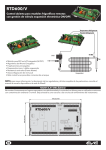
1.1.1 The RTD Input Modules allow RTD temperature sensors to be directly connected to the PLC
without external signal processing (transducers, transmitters, etc.). All analog and digital processing of
the RTD signal is performed on the module, and temperature values in 0.5°C or 0.5°F increments
(RTD600) or 0.125°C, 0.1°C or 0.1°F (RTD601) increments are written to the 90-30 %AI input table. All
modules feature six channels, and support PT-90 (MIL-7990); PT-100E, PT-100C, and PT-100Z; Ni-120,
Cu-10, Cu-50, Cu-53, Cu-100, Pt-1000, TD5R and Linear Resistance.
Figure 1.1 – Front View
PAGE 8
04 NOV 2005
MAN0073-11
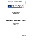
Figure 1.2 – Side View
1.2
Specifications
Table 1.1 - HE693RTD600/601 Specifications
Power Consumption
(Typical)
Pt-100E
alpha=.00385
Pt-100C
alpha=.003902
Pt-100Z
alpha=.03906
Pt-1000
Cu-10
Types
Supported
75mA @ 5VDC
Number of Channels
6
-100 to 850°C
I/O Points Required
6%AI
-100 to 650°C
Input Impedance
>1000 Meg Ω
-200 to 300°C
Fault Protection
Zener Diode Clamp
-100 to 850°C
-200 to 260°C
A/D Conversion Type
Update Time
Average RTD current,
PT-100
Channel to Channel
Tracking
Cu-50
0 to 100°C
Cu-53
-200 to 260°C
Cu-100
-200 to 200°C
Resolution
Ni-120
-100 to 270°C
Accuracy
Linear
TD5R
0 to 200Ω
-40 to 150°C
Operating Temperature
Relative Humidity
Pt-90
(MIL-7990)
-50 to 200°C
16 bit, Integrating
50 Channels per second
330 microamps
0.1°C
0.125°C,
0.1°C,or0.
1°F
± 0.5°C typical,
± 1.0°C for Cu-10 and
TD5R
0 to 60°C (32° to 140°F)
5% to 95% non-condensing
0.5°C or 0.5°F
MAN0073-11
04 NOV 2005
PAGE 9
CHAPTER 2: CONFIGURATION
2.1
General
2.1.1 Chapter Two describes the procedures and set-up for I/O configuration using LogicMaster™
software.
2.2
Configuration
1. Upon entering the LogicMaster™ 90 Software, select ‘LogicMaster Configuration Package’ (F2)
from the menu.
Figure 2.1 – Default Screen
2. To reach the configuration screen, select ‘I/O Configuration’ (F1), from the menu
Figure 2.2 – Configuration Screen
PAGE 10
04 NOV 2005
3. Move cursor to the designated slot containing the module and select ‘Other’ (F8).
Figure 2.3 – Rack Configuration
4. From the following screen, select ‘Foreign’ (F3).
Figure 2.4 – Slot Configuration
MAN0073-11
MAN0073-11
04 NOV 2005
PAGE 11
5. The screen (shown in Figure 2.5) should appear:
Figure 2.5 – Module Configuration
2.2.1 Configuration Parameters
2.2.1.1 Tables 2.1 and 2.2 indicate the five necessary parameters for configuring the HE693RTD600 and
the HE693RTD601 respectively. The parameters include % AI Size, Byte 1, Byte 2, Byte 3, and Byte 4.
2.2.1.2 Change the various bytes (1-4) and set %AI to ‘6’ to reach the desired set-up.
%AI Size
6
Table 2.1 – Configuration Parameters for RTD 600
Byte 1
Byte 2
Byte 3
Byte 4
0001
0000
thru
0111
(see chart)
00=Pt-100E
01=Ni-120
02=Pt-100C
03=Cu-10
04=LIN100
05=Pt-1000
06=TD5R
07=Pt-100Z
08=Cu-50
09=Cu-53
0A=Cu-100
0B=Pt-90
00=0.5°C
01=0.5°F
PAGE 12
04 NOV 2005
%AI Size
Table 2.2 – Configuration Parameters for RTD601
Byte 1
Byte 2
Byte 3
Byte 4
6
2.2.2
0000
thru
0111
(see chart)
0001
00=Pt-100E
01=Ni-120
02=Pt-100C
03=Cu-10
04=LIN100
05=Pt-1000
06=TD5R
07=Pt-100Z
08=Cu-50
09=Cu-53
0A=Cu-100
0B=Pt-90
MAN0073-11
00=0.125°C
01=0.1°C
02=0.1°F
Digital Filtering
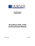
2.2.2.1 The effect of digital filtering (on the HE693RTD600/601module) in response to a temperature
change is graphically represented in Figure 2.6. (%temp change completed vs. time). Byte 2 sets the
amount of digital filtering.
100
90
80
70
60
50
40
30
20
10
0
Figure 2.6 - The Effects of Digital Filtering
MAN0073-11
2.2.3
04 NOV 2005
PAGE 13
Temperature Scaling
2.2.3.1 The Resistance Temperature Device reports values to the %AI table in 0.5, 0.125, or 0.1
increments in either °C or °F. Conversion to actual degrees can be calculated using Table 2.3.
Note: the module configuration depends on the parameter assigned to Byte 4.
Table 2.3 - Temperature Scaling
Module
Temperature
Configuration
Conversion
0.5°C
°C=%AI/2
0.5°F
°F=%AI/2
0.125°C
°C=%AI/8
0.1°C
°C=%AI/10
0.1°F
°F=%AI/10
LIN100 reports 128 counts per 1Ω.
Examples:
If %AI2 equals Channel 2 on the RTD module, and %AI2 equals 1,000, the temperature reading is
T=100°C ( format .1°C).
If %AI2equals 1,000 and Byte 4 equals 00 (.125°C or 1/8), the temperature is T=125°C.
PAGE 14
04 NOV 2005
NOTES
MAN0073-11
MAN0073-11
04 NOV 2005
CHAPTER 3: WIRING & INSTALLATION
3.1
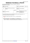
Wiring Diagram for the RTD Terminal Block Connection
NC
Figure 3.1 – Wiring Diagram
PAGE 15
PAGE 16
3.1.1
04 NOV 2005
MAN0073-11
Three-Wire Connection
3.1.1.1 Figure 3.2 shows how to make a three-wire connection with an RTD module.
(Refer to Figure 3.1.)
For example, Channel 8:
Excitation
8
Sense
9
Terminal
Connections
Common
10
Figure 3.2 – Three-Wire Connection
3.1.2
Two-Wire Connection
3.1.2.1 Figure 3.3 shows how to make a two-wire connection with an RTD module.
(Refer to the Figure 3.1.)
For example, Channel 5:
Excitation
14
15
*NOTE: 14 &15
shorted together
Terminal
Connections
Common
16
Figure 3.3 – Two-Wire Connection
NOTE: Two-wire RTDs are supported, but accuracy may vary.
Four-Wire RTDs are NOT supported
3.2
Installation Requirements
a.
b
c.
c.
Wiring should be routed in its own conduit.
Shielded, twisted wiring offers the best noise immunity.
If shielded wiring is used, a good earth ground connection (on one end only) is critical.
If shields are connected at the module end, terminals 1 or 20 may be used as the shield ground
point.
The lead resistance of each wire should be no more than 50Ω.
All unused channels should be shorted together and connected to pins 1 or 20.
d.
e.