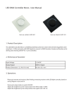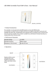
1
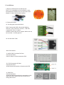
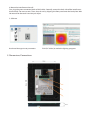
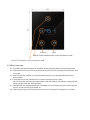
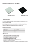
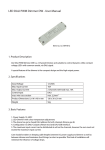
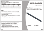
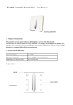
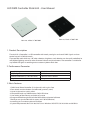
LED DMX Controller Stick GA2 - User Manual
Item no.: black: LC-007-104
Item no.: white: LC-007-004
1. Product Description
The stick GA 2 Controller is a LED controller with touch panel glass and sends DMX Signals and can
control up to 512 DMX channels.
The controller with which on / off, color selection, brightness and selection can be set of predefined or
self-defined lighting scenes for ease of control 4 touch sensitive buttons. The controller is suitable for
any RGBW LED light. Assembling onto a customary 68mm flush box.
2. Performance Parameter
Supply Voltage
Output Signal
Product Dimensions (L x W x H in mm)
Weight
5,5-12V / max 5W
DMX512
L 86 x W 110 x H 10 mm
130 g
3. Basic Features
1. DMX Stand Alone Controller (512 channels) with a glass face
2. Four touch sensitive buttons (on/off mode, previous, next)
3. Up to 99 dynamic or static scenes
4. Compatible with any DMX fixture or DMX LED driver
5. Live setting of the intensity and color of a scene
6. Programmable through the included USB cable and control software
7. Ready to use (pre-loaded with 8 scenes and 170 RGB fixtures)
8. mounting on a customary 68 mm flush box
9. System Requirement: Mac OSx 10.6/10.7/10.8 - Windows XP/VISTA/7/8 32/64 bits and USB 2.0
4. Installation
1. Mount an electrical box inside the wall
The S.T.I.C.K. controller can be installed in a standard electrical backbox. You can insert the AC/DC
adapter inside or outside the backbox.
2. Connect the wires:
2a. Use the green connector block :
DMX: Connect the DMX calbe to the llighting
receivers. (Led‘s, Dimmer‘s, Fixture‘s,...) (for XLR:
1=ground, 2=dmx+, 3=dmx-)
POWER: Connect the AC/DC adapter. Make sure not
to invert the + and the ground.
2b. Use the RJ45 Cable:
other Connections:
3a. 20 PIN CMS Connector for Ports:
remove the Sticker
mount a 20 pin surface connector (CMS)
3b. 5 PIN Connectors for Ports:
remove the sticker
solder the port connections directly to the PCB
3c. DMX Chip:
remove the sticker
solder the DMX chip to the 8 pin connector on the
right of the RJ45 socket. Be sure that the chip is
facing downwards
4. Mount the interface on the wall:
First, plug the green connector block or RJ45 cable. Secondly, mount the back side of the interface on
the wall with 2 or more screws. Then, close th unit by clipping the front panel onto the back plate. Wait
30 seconds for the touch sensitivity to adjust.
5. Software
Hardware Manager to set parameters
5. Dimensions/Connections
ESA2 (PC & Mac) to make the lighting programs
Previous
Next
MODE: Switch between color, scene and dimmer mode
ON/OFF: Short touch - easily switch on and off
6. Safety warnings
6.1. To avoid installed the product in minefield, strong magnetic field and high voltage area.
6.2. To ensure the wiring is correct and firm avoiding short circuit damages to components and
cause fire.
6.3. Please install the product in a well ventilated area to ensure appropriate temperature
environment.
6.4. The product must be worked with DC constant voltage power supply.
Please check the consistence of input power with the product, if the output voltage of the
power comply with that of the product.
6.5. Connect the wire with the power on is forbidden. Ensure proper wiring first then check to
ensure no short-circuit, then power on.
6.6. Don‘t repair it by yourself whenever an error occur. Contact the supplier for any inquiry.