1
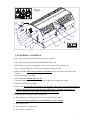
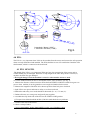
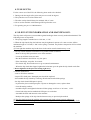
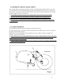
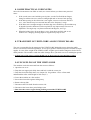
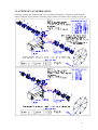
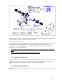
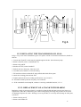
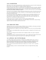
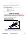
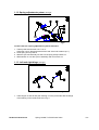
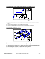
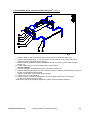
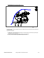
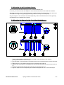
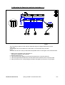
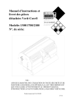
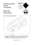
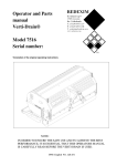
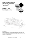
Operator and Parts
manual
Verti-Core®
Redexim
Models 1300/1700/2100
Serial number:
NOTE:
IN ORDER TO ENSURE THE SAFE USE AND TO ACHIEVE THE
BEST PERFORMANCE, IT IS ESSENTIAL THAT THIS OPERATORS
MANUAL IS CAREFULLY READ BEFORE THE VERTI-CORE IS
USED.
Product manual code 914.120.400
FOREWORD.
Congratulations on the purchase of your VERTI-CORE. To ensure the safe and lasting
operations of this VERTI-CORE you (and anyone using the machine) should read and
understand this user’s manual. A complete knowledge of the contents of the manual is
necessary in order to ensure the safe use of this machine.
The VERTI-CORE is not an independently operating machine. It is the responsibility of the
user to use the correct tractor. The user will also need to check the tractor / VERTI-CORE
combination on safety aspects, noise level, user instructions and risk analysis.
The VERTI-CORE is intended exclusively for grass fields or areas on which grass can grow.
On the following page, we will begin with the safety instructions. Every user must be familiar
with these instructions and must follow them carefully. Below you will find a registration
card, which should be returned to us so that we are able to process any future claims.
In this manual, many instructions are given which are stated in a number sequence. The user
must follow the instructions according to this sequence. If the * appears this refers to safety
instructions. If the @ is used, this refers to a tip and/ or note.
GUARANTEE CONDITIONS.
THIS VERTI-CORE PRODUCT IS DELIVERED TO THE CUSTOMER
ACCOMMPANIED BY A GUARANTEE AGAINST DEFECTS IN THE MATERIALS
USED. THIS GUARANTEE APPLIES FOR A PERIOD OF 12 MONTHS AS OF THE
DATE OF PURCHASE.
VERTI-CORE GUARANTEES ARE SUBJECTED TO THE "GENERAL CONDITIONS
FOR SUPPLY OF PLANT AND MACHINERY FOR EXPORT, NUMBER 188", WHICH
ARE PUBLISHED UNDER THE AUSPICES OF THE UNITED NATIONS ECONOMIC
COMMISSION FOR EUROPE.
REGISTRATION CARD.
For your own record, copy the information from the registration card to the table hereunder
Serial number of machine
Name of your distributor
Date of purchase
Any remarks
2
SAFETY INSTRUCTIONS.
1.
Always use the VERTI-CORE with the correct tractor as described in the
technical information
2.
The user is responsible for a safe Tractor/VERTI-CORE combination. The
combination must be tested for noise, safety, risk and easy usage. It is also necessary
to draw up user instructions.
3.
The VERTI-CORE is suited exclusively to grass fields.
4.
Every VERTI-CORE user must be fully informed of the information contained in
the user manual.
5.
Inspect the ground where the VERTI-CORE is to be applied. Remove loose
obstacles, avoid uneven ground.
6.
Never step off the tractor if the engine is still running.
7.
Ensure that other people are standing at least 4 mtr. (14' ) away from the
VERTI-CORE.
8.
Use appropriate clothing. Wear strong shoes with a steel inforced toe cap, long
trousers, tie up long hair. Do not have any loose pieces of clothing.
9.
Never try to force the VERTI-CORE, a situation which is visible in the partial
loosening of the front roller from the ground and unstable behavior of the VERTICORE.
10.
Check the VERTI-CORE once a week to ensure there are no loose screws or
nuts and bolts.
11.
The VERTI-CORE may never be used without protection covers and safety
stickers.
12.
NEVER crawl underneath the VERTI-CORE. If you need to work underneath,
turn the VERTI-CORE on its front.
13.
Always switch off the engine and uncouple the power take off, before starting
any maintenance, adjustment or repair. Also block the VERTI-CORE against sinking
and block it against forward/backward movement or sliding.
14.
Use only the original VERTI-CORE spare parts/ tines in order to ensure the safe
operation of the machine.
15.
Never use the VERTI-CORE in the dark, in heavy rain, on frozen ground, stormy
conditions or on slopes greater than 20 degrees.
16.
Before operating the machine, also read the instructions and the maintenance
information for the power take off. This component has its own certification mark.
17.
Maintain a log book of repairs.
18.
If any modifications are carried out on the machine the CE certification mark will
be no longer valid. The User/Dealer himself must then have the machine recertified.
3
CONTENTS.
Paragraphe Description
Page
Foreword
2
Guarantee conditions
2
Registration card
2
Safety instruction
3
1.0
Technical specification
5
2.0
First setup, lifting machine from pallet
6
3.0
General controls
7
4.0
PTO
8
4.1
PTO length
8
4.2
Use of PTO
9
4.3
Slip clutch information and maintenance
9
5.0
Working depth adjustment
10
6.0
Groundspeed
10
7.0
Starting procedures
11
8.0
General usage of Verti-Drain
11
8.1
Some practical user notes
12
8.2
Transport of Verti-Drain
12
9.0
Uncoupling of the Verti-Drain
12
10.0
Problem analysis
13
11.0
Maintenance
14
12.0
EU-Declaration
14
13.0
Technical information
15
13.1
Torque settings
16
13.2
The crankshaft
16
13.2.1
Replacing the transmission oil seal
17
13.2.2
Replacing of a crank and crank bearing
17
13.2.3
Removing the crankshaft tension
18
Options, tines
18
14.0.1
Solid tines
19
14.0.2
Hollow tines
19
14.1
Options, Multi tine heads
19
14.2
Options, Windrow kit
20
14.3
Options, Turf hold down kit
21
14.0
4
1.0 TECHNICAL SPECIFICATIONS
Model
1300
1700
2100
Overall dimension
(LxWxH)
Working width
885x 1450x 700 mm
(35 x 58 x 28”)
1.30 mtr ( 52”)
885x 1855x 700
(35 x 74 x 28”)
1.70 mtr (68”)
885x 2265x 700
(35 x 91 x 28”)
2.10 mtr ( 84”)
Working depth
Up to 125 mm (5”)
Up to 125 mm (5”)
Up to 125 mm (5”)
1.7 km/h (1.1 mph)
1.7 km/h (1.1 mph)
3.3 km/h (2.2 mph)
3.3 km/h (2.2 mph)
Up to 540 rpm
Up to 540 rpm
Tractor speed @540 rev’s
at PTO
Hole spacing 52 mm (2- 1.7 km/h (1.1 mph)
1/16”)
3.3 km/h (2.2 mph)
Hole spacing 100 mm
(4”)
PTO speed
Up to 540 rpm
Weight
480 Kg (1050 lbs)
550 Kg (1210 lbs)
625 Kg (1375 lbs)
Hole spacing side-to-side
52 mm (2-1/16”)
52 mm (2-1/16”)
52 mm (2-1/16”)
Hole spacing in drive
direction
Recommended minimum
tractor size
25- 100 mm (1- 4”)
25- 100 mm (1- 4”)
25- 100 mm (1- 4”)
22 Hp with minimum
lift capacity of 650 kg
(1450 lbs)
28 Hp with minimum 35 Hp with minimum
lift capacity of 750 kg lift capacity of 850 kg
(1670 lbs)
(1890 lbs)
Capacity :
Spacing 52 mm (2-1/16”) Up to 2061 m³/hour
(22181 sq ft/hour)
Up to 3964 m³/hour
Spacing 100 mm (4”)
(42655 sq ft/hour)
Shipping dimensions
700 x 1450 x 900 mm
(L x W x H)
(28 x 58 x 36 “)
Three point linkage
3-point Cat 1
Up to 2696 m³/hour
(29006 sq ft/hour)
Up to 5184 m³/hour
(55780 sq ft/hour)
700 x 1860 x 900
(28 x 74 x 36 “)
3-point Cat 1
Transmission grease
Life time grease EP00
Life time grease EP00 Life time grease EP00
Lubrication grease
EP 2
EP 2
Slip clutch setting (Max)
400 Nm (3540 lb.inch)
400 Nm (3540 lb.inch) 400 Nm (3540 lb.inch)
Standard items
Set hollow tines 13/16 x
6 top & side eject
PTO
Turf hold down kit
Turf hold down fingers
multi tine head
Multi tine heads
Windrow kit
Set hollow tines 13/16
x 6 top & side eject
PTO
Turf hold down kit
Turf hold down
fingers multi tine head
Multi tine heads
Windrow kit
Options
Up to 3330 m³/hour
(35830 sq ft/hour)
Up to 6404 m³/hour
(68905 sq ft/hour)
700 x 2280 x 900
( 28 x 92 x 36”)
3-point Cat 1
EP 2
Set hollow tines 13/16
x 6 top & side eject
PTO
Turf hold down kit
Turf hold down
fingers multi tine head
Multi tine heads
Windrow kit
Fig.1.
2.0 FIRST SETUP, LIFTING MACHINE FROM PALLET.
The machine stands vertically up on the pallet. To remove the pallet and get the machine
horizontal on the ground, handle as follows (see fig.1 ):
1. Open the rear cover
2. Connect a cable to main chassis
* ensure the cable/crane/lift truck can lift minimum 1000 Kg.(2200 lbs).
3. Raise machine with pallet 50 mm (2")from the ground.
4. Remove pallet by sliding it over the bottom 3-point pins
* Do not crawl under the machine
5. Lower the machine gentle till 3-point connecting plates contact the ground.
6. Drop the machine further, enabling it to rotate on its front roller.
7. Gently lower the machine till it stands on the front roller and rear support jack.
8. Connect the machine to a tractor.
* Use correct tractor see specifications.
9. Lower the machine on the ground and adjust the angle of 90 degrees with top link
@ this angle is very important, see further.
10. Adjust tractor lower link stabilizers to limit sideways movement till about 100 mm (4”).
12. Assemble the tines. Use some grease on the shank.
13. PTO length, see 3.1
6
Fig.2.
3.0 GENERAL CONTROLS
In fig.2. some key details of the machine are shown, as follows:
1. PTO input shaft. Slip clutch should be assembled at this shaft.
2. PTO protection covers at the machine. Top one can be removed for maintenance.
3. Lower 3-point linkage pins. May be repositioned and facing in or out.
4. Safety decal RA, before using machine read manual. Decal is located at the toolbox with
manual.
5. Front roller support lock bolts.
6. Protection shield. Should always be on.
7. Working depth indicator. Note the indication is related to maximum tine length.
8. Spindle to adjust working depth.
9. Safety decal, Keep 4 mtr (14') distance to the machine .Turn engine off when maintaining or
repairing machine and watch moving parts/ tight spaces, squeezing your fingers etc.
* All decal should be on the machine and understood all the time
10. Serial number of machine can be found inside
11. Knurled nuts for securing the rear access door of the VERTI-CORE.
* rear access door should always be closed and free of any damage.
12. Rear support jack.
13. Secure pin for rear support jack.
14. R pin to lock secure pin 13.
7
Lstandard= 34mm (1.339")
L minimum= 32.5mm (1.280")
Fig.3.
4.0 PTO.
The PTO is a very important item. It drives the machine from the tractor and ensures the safe operation
when correctly maintained and installed. The PTO shaft has its own CE certification. Read the PTO
shaft manual, which is connected to the shaft itself.
4.1 PTO LENGTH.
The length of the PTO is very important. When too long, the transmission of the tractor and/or
VERTI-CORE may be damaged. When the overlap length of the tubes drops under 150 mm (6")
anytime, the PTO may get damaged.
* the length changes when the machine is raised or when another tractor is used.
To cut the standard PTO from new or for another tractor, work as follows (see fig. 3):
1. Measure the distance A between tractor PTO shaft and VERTI-CORE PTO shaft from groove to
groove when machine is on the ground at correct angle and attached to the tractor.
2. Measure the length B of the PTO in its shortest position from lock pin to lock bolt.
3. Split PTO in two pieces and remove safety cover from each end
4. Both tubes and safety cover ends should be shortened: (B - A) + 75 mm (3").
5. Deburr all items, use some grease and put all parts together.
6. Assemble the slip clutch side of the PTO to the VERTI-CORE gearbox.
@ Torque for lock bolt should be 80 Nm (700 lb.in.)and checked every 40 hours
7. Connect other side to the tractor.
8. Check overlap of tubes.
* Never run machine with a damaged PTO safety cover. Replace it first.
8
4.2 USE OF PTO
For the correct use of the PTO, the following items need to be checked:
1. During work the angle of the joints may never exceed 30 degrees
2. The joints have to be in line all the time
3. The tube overlap should always be minimal 150 (6") mm
4. Never use the machine with a damaged PTO protection cover.
5. For greasing see par. 11.0 Maintenance.
4.3 SLIPCLUTCH INFORMATION AND MAINTENANCE.
The slip clutch will protect your machine against breakages when correctly used and maintained. The
following items are important.
1. The spring length is standard set at 34.0 mm , 1.339".
2. When the slip clutch slips, the bolt/nuts may be tightened a quarter of a turn at a time, till the
minimum length of 32.5mm, 1.280" on the spring is reached. Any further compression will overload
the machine.
@ If too tight the machine may break down in the end or unsafe situations may occur.
3. The slip clutch should be maintained every month. Work as follows;
- Remove the top PTO protection cover of the machine
- Loosen up all bolts/ nuts two turns.
- Run the machine in the field at very low rpm's
- If the clutch slips, stop after 10 seconds.
- If it doesn't slip, loosen bolts more or go to (annual) maintenance.
- When the slip clutch has slipped, tighten the bolts/nuts up to the point the slip clutch works fine.
* Do not tighten it to the previous setting right away.
4. Annual maintenance:
- remove PTO from machine.
- inspect PTO shaft parts. Damaged parts should be replaced.
- disassemble the slip clutch by removing all bolts/nuts that hold the springs
- the slip clutch should fall apart in pieces.
- lay down the pieces and inspect parts. If parts are damaged or worn, replace them.
- clean all mating surfaces.
- assemble all parts and tighten bolts/nuts till the springs are all set at 34.0 mm , 1.339".
- Grease both tubes and assemble both PTO parts to each other.
- Assemble the PTO and mount it to the machine.
- Readjust the springs of the slip clutch when necessary as previously described.
@ The slip clutch protects the machine only against peak loads, when correctly adjusted. A
continuous overload will damage the machine in the long run and is not protected by the slip clutch.
Do not overload your machine.
9
5.0 WORKING DEPTH ADJUSTMENT.
The working depth can be adjusted when the machine is lifted from the ground as follows, see fig. 2:
Unscrew bolts 5 at each side of the machine one turn. Screw spindle 8 in or out. Every revolution is 4
mm (0.160"). The decal 7 at each side of the machine shows the actual depth. When the correct depth
is reached, tighten the bolts 5 at each side.
@ Never adjust one side more than 4 turns. Compensate the other side first before proceeding.
@ The value at the decals is only true when 125 mm (5") long tine are used. When shorter
tines are used, deduct the length difference to the 125 mm (5") from the actual decal reading.
@ Clean and spray the spindle and nut with anti-sticking grease oil every 100 hours, to prevent dirt
sticking on the nut.
6.0 GROUNDSPEED.
The groundspeed determines the hole spacing D in the drive direction.
The input speed B, Fig.4. on the PTO may be maximum 540 rpm. When stones or rocks are expected,
the input speed should be reduced.
With heavier tines or attachments, the tine holders may start to vibrate, causing an irregular hole
spacing.. Lower rpm's at that time.
@ If the machine is not set correctly behind the tractor, see fig.1., different angles at the PTO may cause
vibration in the drive line of the VERTI-CORE. This vibration can hurt the machine and also the
performance of the holes in the ground.
@ If the PTO shaft is incorrectly fitted (too long or too short), extra forces are applied to the input shaft
of the gearbox. Damage may occur.
B
C
A
Fig.4.
10
7.0 STARTING PROCEDURES.
The starting procedure is VERY important. If the start up is not done as described hereunder, serious
damage to the machine may occur. Proceed as follows, see fig.4.:
1. Drive to the spot you want to start the operation.
2. Lower the machine, till the lowest tines are almost on the ground.
3. Set tractor engine at app. 1200 rpm's
4. Put tractor in correct gear, and start moving forward (A)
5. Engage PTO at tractor (B)
6. DURING rolling forwards with the machine RUNNING, GENTLY lower the machine in the
ground (C), till front roller is tight on the ground.
7. Increase engine rpm's till the maximum value advised.
At the end of a pass, quit the operation as follows:
1. Lower engine rpm's till about 1200.
2. Raise machine out of the ground.
3. As soon as all tines are out of the ground, disengage PTO.
4. Raise machine further, till the lowest tines are at least 120 mm (5") above the ground.
5. Move to the next spot and start again as described above.
@ It is absolutely necessary to proceed as described above. If the machine is put into the ground first,
without the PTO running, serious damage may occur.
@ The machine needs to be lowered GENTLY.
@ Be careful with driving backwards.
During work the front roller needs to be stable on the ground. If the machine starts to be unstable,
change the rpm's on the PTO. If this doesn't make any difference, adjust the working depth or change
to other tines who penetrate easier.
@ If nothing is done on the instability of the machine, serious troubles may arise afterwards.
The machine is NOT protected against these circumstances on the long term.
@ Never drive backwards with the tines in or close to the ground.
@ NEVER drive backwards, when the lowest tines are less than 120 mm (5") above the ground. If the
tines get caught, serious damage will appear on the machine.
@ Do not use a hydraulic top link.
8.0 GENERAL USAGE OF THE VERTI-CORE.
The VERTI-CORE can only be used when the circumstances are right. Check the following items:
1. Are there any loose objects on the field. If so, these must be removed first.
2. Are there any slopes. The maximum slope for the VERTI-CORE is 20 degrees. Always operate the
VERTI-CORE from the top to the bottom of a slop.
3. Are there any pipes/wires/cables in the ground. If so, ascertain at what depth and set the working
depth at a maximum of 60% of the pipe etc. depth.
4. Are there any hard objects in the ground. If so, operate the VERTI-CORE with a very low PTO
speed, or adjust working depth.
5. Is there any danger of flying objects such as golf balls, which could distract the attention of the
driver ? If so, the VERTI-CORE can not be operated at that moment.
6. Is there any danger of subsidence or land/mud slides ? If so, the VERTI-CORE cannot be operated
on the field at that moment.
7. Is the ground frozen or very wet. Postpone operation till circumstances are better.
8. When ground is very compacted, use shorter thinner tines to penetrate, or adjust working depth.
11
8.1 SOME PRACTICAL USER NOTES.
Since the circumstances can differ so much, we want to inform you about some practical
notes:
1. If the (weak) roots can’t hold the grass in place, use the Turf hold down fingers,
change to another tine size, reduce working depth and/ or increase hole spacing.
2. If the hole spacing in drive direction is not regular, increase or decrease the PTO
rev’s, since the tine may have entered into their own “frequency” range.
3. If the holes aren’t straight enough or the hole edge isn’t satisfactory, the machine may
be tipped forward or backward via the top link for any improvement. Do not over
adjust this. The angle may vary between 80 and 100 degrees, see Fig. 1.
4. When the hollow tines do not produce a core, clean them carefully and/ or use
another size. Changing working depth or irrigation may help as well.
8.2 TRANSPORT OF VERTI-CORE ALONG PUBLIC ROADS.
The user is responsible for the transport of the VERTI-CORE behind the tractor along the public
streets. Check on the national legislations. Across open ground a maximum speed of 12 km/h (8 mph)
applies. In view of the weight of the VERTI-CORE, a higher speed could be dangerous for the driver
and bystanders. The machine could also suffer damage due to jolt which can occur with higher speeds.
* At least 20% of the tractor weight should rest on the front axle when machine is lifted.
9.0 UNCOUPLING OF THE VERTI-CORE.
The machine can be disconnected from the tractor as follows:
1. Open the rear cover.
2. Drop the rear support jack fully down and lock it with the secure pin
3. Drop the front roller fully down, see chapter 5.0. for guidance. Or use a firm stand
underneath the roller with a height of 125 mm (5”).
4. Lower the machine on a firm surface
5. Secure the front roller against rolling away.
6. Remove the top link.
7. Disconnect the PTO shaft from the tractor side
8. Disconnect the lower three point linkage arms.
* Shut down the tractor engine during walking around the VERTI-CORE.
12
10.0 PROBLEM ANALYSIS.
Machine vibrates
Crankshaft rotates irregular
Machine not at 90 degrees
PTO joint angles different
PTO joints not in line
Tough circumstances
Adjust working depth
Use thinner/ shorter tines
If dry, irrigate first
Solid/ hollow tines
Wrong tine
Change tine, use shorter one
Adjust working depth
Are bending/ breaking
Tough circumstances
Use thinner/ shorter tines
If dry, irrigate first
Quick wearing
Front roller is not stable
Use solids first to break the soil
Wrong tines, too much resistance Change tine size
on the ground
Adjust working depth
Tough circumstances
Use other size tines
Adjust working depth
Irrigate first
Don’t do job in one pass
PTO breakages
Slip clutches slips often
Check setting
Replace lining plates
Clean clutch internally
Tubes are cracking
PTO angles too wide
PTO angles not the same
Damage to the turf
Oval holes
Soil too wet
Change tine angle setting by top link
Reduce forward speed
Turf damage
Adjust working depth
Use thinner tines
Change hole spacing
Crankshaft problems
Big end nuts slacken
Solve vibration, see vibration
Crankshaft bearing collapsed
Incorrectly assembled after repair.
Remove, clean, use loctite
13
11.0 MAINTENANCE.
Pre-Delivery-Inspection
Check bolts/ nuts
Connect the unit to a tractor
Run unit for 5 min
See instructions in this
manual
Look and listen
After first 20 hours
(new or repaired)
Grease PTO and roller
2 shots each EP 2
Check bolts/nuts
Inspect machine closely
After every 100 hours
4 shots each EP 2
Grease PTO and rollers
Check bolts/ nuts
Inspect machine closely
Grease spindles front roller
12.0 EU-Declaration
.
We, Redexim Utrechtseweg 127 3702 AC Zeist Holland, hereby declare fully on our
authority that the product:
VERTI-CORE 1300/ 1700/ 2100, WITH MACHINE NUMBER AS INDICATED ON THE
MACHINE AND IN THIS MANUAL,
to which this declaration applies, has been manufactured in line with NEN-EN 292-1, NEN
292-2 and NEN-EN 294, according to the stipulations of: The Machine Directive 89/392,
updated by 93/368/EEG, 93/44/EEG and 93/68/EEG
Redexim Holland Jan 2002.
14
13.0 TECHNICAL INFORMATION.
Generally speaking, the VERTI-CORE is not a complicated machine. A couple of technical items
will be explained. If you still have questions, please contact your dealer, who is willing to assist you.
Fig.5.
Fig.6.
15
Fig.7.
In the above fig.5, 6 and 7. the torque setting for the several bolts/nuts is given and the timing of the
crankshaft. Refer to the figure that represented your model.
Use the self lock nuts only once.
The machine has three different kind of cranks: one or sometimes two for the gearbox, one for the big
end pin head and one for the big end pin nut. Refer to the part pages for more information
Carefully time the crankshaft after parts are replaced. Damages/ vibrations may occur when not
properly done. Use only genuine parts.
•
Be carefull with moving/ rotating parts inside. They may crunch your fingers , hands and
arms.
•
Place the machine on firm studs, before starting any repair.
13.1 TORQUE SETTINGS.
In fig.5, 6 and 7., the torque settings of the most important bolts/nuts are given. For the ones the torque
setting is not mentioned, please be sure that they are tightened as a similar size bolt/nut would be
tightened. If bolts/nuts are working themselves loose, loctite may be applied.
13.2 THE CRANKSHAFT.
In fig.8. the assembly of the crankshaft is given. Also look at the spare part page for a more clear view
and setup.
16
Gearbox
Fig.8.
13.2.1 REPLACING THE TRANSMISSION OIL SEAL.
In fig.8. a top view of the crankshaft is given. To replace a main oil seal at the transmission, handle as
follows:
1. Loosen nuts II and IV, which may be tight through the loctite. Some heat may help.
2. Remove nuts III, remove crank handles VI.
3. Remove big end IX.
4. Slacken nut VIII, remove handle X.
5. Pull oil seal out, clean area, insert new seal..
6. Assemble (new) handle X, watch the timing.
7. Fill outside area between handle X and profiled shaft with silicon paste.
8. Attach new locking plate and nut VIII.
9. Tighten and lock the nut according specifications (fig.5,6 and 7).
10. Assemble all other parts the way they were removed.
11. If the crankshaft seems lumpish, continue “removing crankshaft tension”, 15.2.3
13.2.2. REPLACEMENT OF A CRANK WITH BEARING.
Replacing a crank is necessary when it is cracked or when the big end nuts start to come loose on a
regular base. Either the crank bearing, the crank bearing fitting or the big end pin holes in the crank
are damaged. Replace the crank / bearing as soon as possible, to avoid any more damage to other parts,
as follows:
1. Remove the big end V.
2. Remove the handles IV.
17
3. Take the profiled shaft with bearing out.
4. Remove bearing from profiled shaft.
5. Replace the parts and assemble the other way round.
@ Use loctite for nut II, III and VIII.
13.2.3 REMOVING THE CRANKSHAFT TENSION.
If parts have been replaced on the crankshaft, the crankshaft may seem running tight. This is because
of possible tension in the crankshaft parts. It is necessary to remove these, as follows ,see fig.8.:
1. Tap the center of the crank adjacent to the gearbox, alternately left and right.
2. Feel whether the crank moves and continue till the crank has nested.
3. Repeat this operation with the adjacent crank and continue this way till the crankshaft will operate
more smoothly.
@ After any repair on the crankshaft, the crankshaft nuts should be checked regularly, after first 10
hours.
@ Don’t assemble the cranks at the wrong side of the machine. See the spare part for the right part
numbers.
14.0 OPTIONS, TINES
Tines are essential for the correct working of the machine. Several tines are available for this machine,
see the spare part pages for a total overview. Generally speaking, tines can be divided into two
categories: Solids and Hollows. We advise using genuine tines, since they are fully adapted to the
machine.
In fig.9,10 and 11. several tine combination are given. The standard tine holders have 4 x 19 mm
(3/4”) holes for mounting tines. The lock bolt L may be tightened till 80 Nm (60 lbs.ft.).
Fig.9.
Fig.10.
Fig.11.
18
14.0.1 SOLID TINES.
When tines are new, they may disrupt the turf, specially when the root system is weak. Clean the tines
first by hand or use the machine for 10 minutes at another rougher area.
If the root system is weak, don’t try to penetrate the soil much deeper than the root system. Adjust the
working depth till the penetration is about 50 mm (2”) more than the root system depth. This allows
the roots to grow deeper. Next time penetrate deeper. Using this method will safe you from disrupting
the turf and will establish a healthy root system.
We advise to use the solid tines with the sharp point facing to the front roller. This will create the best
tine action in the ground. However with a weak turf, it is worth using the tines with the sharp edge
facing away of the front roller.
Use always tines with the same length and size. Replace a bent tine immediately. When this is not
done, the machine can be unstable. Don’t use any thicker/ longer tines as what is offered by us.
If oval holes are created, it means that we have a weak top layer and a hard pan underneath. Use
thinner tines or wait till the (wet) top layer has dried.
If topdressing needs to be applied, spread it first before using the VERTI-CORE.
If the ground is hard to penetrate, irrigate first, use smaller diameter shorter tines or adjust working
depth. If not done, the machine will be hurt in the end.
14.0.2 HOLLOW TINES.
With hollow tines, the soil can be exchanged. Different sizes are available, see the spare part manual.
When used, the side outlet should face to the rear of the machine.
If top dressing needs to be applied, use the VERTI-CORE first, remove the cores and start spreading
the sand.
If a lot of dirt is created during hollow coring, reduce your rpm’s or irrigate first. The dirt may wear
your machine
When the turf is damaged use the solid tines first to establish a healthy root system or adjust the
working depth.
If the hollow tines block, it mat mean that the ground is (very) compacted and solids need to be used
first to break the ground. Irrigation may help as well, as adjusting the working depth.
14.1 OPTIONS, MULTI TINE HEADS.
Two different kind of multi tine heads are available for the VERTI-CORE, see fig. 10 and 11.
In fig. 10 the multi tine head for 8 mm (3/8”) is drawn, that can take up to 6 tines in two rows.
We can fit smaller solid and hollow tines into this adapter. The adapter is mounted to the tine
holder of the machine via an angle bracket that is assembled to the multi tine head first.
Fig. 11 shows the mini needle tine head with 21 solid tines 5 x 125 mm ( 5/16”x 5”), divided
over 3 rows.
Generally speaking, we advise to reduce the number of tines in an adapter when they disrupt
the turf.
19
14.2 OPTIONS, WINDROW KIT.
A windrow kit can be assembled at the rear side of the VERTI-CORE, as drawn in Fig.12.
The pivot angle supports 11 and 12 can be mounted to the mainframe with bolts A, using
holes B. These supports can stay on the machine. Next the support arms 13 can be mounted
with bolts/ nuts 14/15. Do not fully tighten, because the arm 13 should pivot around bolt 14.
Next both panels can be prepared. All parts are identical. It is however important that the
longest end from the panel 1, faces the farest away from the machine, so that the panels never
dig in the ground when moving forwards. Bolt the angle profiles 4 on, do not tighten. Slide
the shaft 7 through all holes, including the support arm 13 and washers 5 (check positions
carefully with drawing). When the R pins 2 are fixed. It should be firm, without a lot of play.
Next tighten the bolts/nuts 6/3. Since some play is available at the holes, some corrections can
be made. Check whether the kit is flexible.
The lock bolt 9 prevents the arm 13 from falling down. Use the washers 8 to limit the travel.
If the travel needs to be further reduced, use even larger diameter washers.
@ No springs or chains are needed. In the end a flexible, contour following windrow kit is
created without any adjustable items.
@ If working depth is adjusted, no adjustments at the windrow are necessary.
@ For removing the windrow kit, just take bolts 14 out
@ Tighten bolts A tight and leave 11 and 12 at the machine.
•
Be carefull with backing up the unit. Check the lift height first. Correct when
necessary.
•
Remove the windrow kit when not needed. Be careful when driving around the
machine with the windrow kit at the back.
20
Assembly
Instructions:
Redexim
REDEXIM BV
INTERNATIONAL TRADING
KWEKERIJWEG 8
3709 JA ZEIST HOLLAND
TEL (31) 30 6933227
FAX (31) 30 6933228
[email protected]
WWW.REDEXIM.COM
Spring Loaded Turf Hold Down
Frame Verti-Core® 1300/1700/2100
Redexim-Charterhouse
Spring Loaded Turf Hold Down frame
1/11
! SAFETY INSTRUCTIONS !
Before you begin to assemble the Spring Loaded Turf Hold Down Frame you have to follow up
these safety instructions for a safe and correct mounting procedure.
•
•
During assembly and disassembly the machine has to be blocked against moving.
If you use a tractor to lift the machine:
•
•
•
•
•
•
Always switch the tractor engine off
Remove the tractor ignition key
Disconnect the PTO
Block the tractor against moving.
Never crawl underneath the machine
Be aware of sharp edges.
1.0 MOUNTING PROCEDURE
Before assembling the frame you have to be aware and following up the Safety Instructions!
The quantity of bolts are different for the 3 machines, to see which quantities are suited for
your type machine see the parts list provided at page nr 11
The numbers given in the figures are corresponding with the numbers on the parts page to
make it easier to mount the right parts at the right position.
1.1Mounting of the subassemblies
1.1.1 Main Beam with scraper and clamp strip. (see fig.1)
fig.1
1. Take main-beam 21 and mount the scraper-strip 23 with bolts 24 and nuts 22.
Do not tighten the strip because you have to adjust it later to tune it right on your front roller.
2. Take clamp-strip 18 and mount it to the main-beam 21 with bolts 19 and nuts 17.
(for the 3- and 4-tines fingers use the rectangular holes!!) Do not tighten these bolts and nuts.
Redexim-Charterhouse
Spring Loaded Turf Hold Down frame
2/11
1.1.2 Spring adjustment system. (see fig.2)
fig.2
On the frame are 2 spring adjustment systems mounted.
1. Take eye-bolt 9 and screw nuts 11 on it.
Adjust the nuts so that the distance till the end of the bolt is 55mm (2.2”).
2. Hook spring 8 on eye-bolt 9.
3. Slide the eye-bolt assembly into the hole of spring clamp bracket 12.
4. Slide washer 14 over the eye-nut assembly and mount knob 15.
1.1.3 Left and right hinge. (see fig.3)
fig.3
1. Take Hinges 13 and 25 and push bearing 16 in the pivot holes with the flange
of the bearing on the inside as shown in fig.3.
Redexim-Charterhouse
Spring Loaded Turf Hold Down frame
3/11
1.2 Disassembly of the existing fixed turf hold down beam (see fig. 4)
fig.4
1. Remove bolts and nuts 1 and 2 on both sides of the machine to remove the old turf hold down
beam 3.
2. Remove bolts and nuts 6 and 7 on both sides of the machine.
3. Remove the old roll scraper by loosening nuts 8 and removing the scraper-line.
1.3 Assembly of the pivot (see fig. 5)
fig.5
1. Make sure that the Verti-Core® is secured and blocked against moving.
2. Lift the Verti-Core® a few millimetres upwards so that the pressure is just of the front roller.
3. Remove the existing bolts 7a and nuts 8a.
4. Take weld-assy pivot 2 and mount it on the side of the support with bolts 3 and self locking nuts 4.
5. Mount Distance bush 5 with Bolt 10 from the inside out on the support.
Use self locking nut 1 (same nut as nut 6 in capital 1.2) to tighten bolt 10.
6. Do the same to the other side of the machine.
Redexim-Charterhouse
Spring Loaded Turf Hold Down frame
4/11
1.4 Assembly of the system on the Verti-Core® (see fig. 6)
fig.6
1. Take the bolts 20 and put them through the hole in the main-beam assembly 12a.
2. Take the left and right hinge 11a and put them over the bolts 20 on top of the-main beam
assembly 12a on both sides of the machine.
3. Take the spring adjustment system assemblies 9a and mount it on top of the left and right
hinges 11a.
4. Take the self locking nuts 10 and attach them to the bolts 20.
!!Do not tighten!!
5. Take the complete assembly and move it over the front roller 13a.
6. Slide the left and right hinges 11a over the shaft of the pivot 3 till they meet the side of the pivot.
Do this on both sides of the machine.
7. Align the main-beam in the middle of the machine.
8. Tighten the nuts 10 and bolts 20.
9. Take the roll pin 2 and put it through the hole on the shaft of pivot 3 to lock the hinge.
Do this on both sides of the machine.
10.Mount the springs of the spring adjustment system 9a to the distance bushes 6
Redexim-Charterhouse
Spring Loaded Turf Hold Down frame
5/11
2.0 Adjusting the scraper strip (see fig. 7)
fig.7
To let the scraper strip work properly you have to adjust it after you mounted the spring loaded turf
hold down beam.
This works as followed:
1. Loosen nuts 1 and move the scraper strip 2 up or down (shown by the arrow) to get the right
adjustment for your Verti-Core®.
2. The strip should be adjusted so that the roller 3 can rotate freely.
3. When you have found the right adjustment tighten the nuts 1.
Redexim-Charterhouse
Spring Loaded Turf Hold Down frame
6/11
3.0 Mounting the turf hold down fingers
The kit is delivered standard with fingers for the 4-tines tineholder, but
of course you can mount also the fingers for the 3-tine tineholder and for the multi-tine tineholder.
The fingers of the 3- and 4-tines tineholder are mounted with help of a clamp strip so you can mount
and replace the fingers very quickly by loosening a few nuts on top of the clamp strip.
Only the fingers for the multi-tines are bolted separately to the main beam because of the geometry
and difference in the material of the fingers.
3.1 Mounting the fingers for the 3- or 4-tine tineholder (fig.8)
fig.8
1. Take the fingers which you like to mount and begin on the right side of the machine.
(Facing the backside of the machine)
2. The first finger on the right side of the machine has to be mounted first; take out bolt 19 and nut
17.
3. Slide finger 26 or 27 between the main beam 21 and the clamp strip 18.
4. Slide the bolt 19 through the rectangular hole and through the clamp strip and mount it with nut
17.
5. Divide the other fingers between the main beam 21 and clamp strip 18.
6. Align the fingers to the corresponding tine holders and tighten the nuts 17 to fix the fingers.
Redexim-Charterhouse
Spring Loaded Turf Hold Down frame
7/11
3.1.1 Reversed mounting the fingers for the 3- or 4-tine tineholder (fig.9)
fig.9
If it is needed to mount the the fingers with the closed side on the surface then this is possible on this
new system. You simply turn the fingers around and slide it between the clamping system.
Do this as described below:
1. If not already done; loosen the nuts 17 of the clamping device.
2. Divide the fingers 26 or 27 between the main beam 21 and clamp strip 18.
3. Align the fingers to the corresponding tine holders and tighten the nuts 17 to fix the fingers.
Redexim-Charterhouse
Spring Loaded Turf Hold Down frame
8/11
3.2 Mounting the fingers for multi-tine tineholder (fig.10)
fig.10
The mounting procedure for the multi-tine tineholder fingers is slightly different than for the
other ones.
These fingers have to be bolted on the main beam; to do this follow the procedure
below.
The bolts 29 and nuts 30 are provided with the separate frame for the fingers of the multi-tineholder
1. Begin on the right side of the main beam 21.
(Facing the backside of the machine)
2. Remove clamp strip 18
3. Take the bolts 29 and slide them through the square hole on the main-beam 21.
4. Take the fingers 28 and slide them over the bolt 29 with the sleeve holes on the other side.
5. Align the fingers to the corresponding tine holders and tighten the nuts 30 to fix the fingers.
Redexim-Charterhouse
Spring Loaded Turf Hold Down frame
9/11
4.0 Short description of the spring adjustment system (fig.11)
The turf hold down beam is as mentioned in it's name spring loaded, this means that the turf hold
down beam always move the turf hold down fingers to the ground.
It doesn't matter in which angle the Verti-Core® stands to the surface, the turf hold down fingers
will meet the ground and when the surface is uneven it will also follow the surface under spring
load.
The pressure load of the turf hold down fingers that is working on the surface can be adjusted by
turning the knob 15.
Clockwise for more pressure and counter-clockwise for less.
This feature makes you able to set the pressure load which you think that is good for the surface!
Redexim-Charterhouse
Spring Loaded Turf Hold Down frame
10/11
Redexim-Charterhouse
1
2
3
4
5
6
7
8
9
10
11
12
13
14
15
16
17
18
19
20
21
22
23
24
25
26
27
28
Verti-Core THD Spring Loaded 1300/1700/2100 code 1904
PART #
1300
PART #
1700
PART #
2100
DESCRIPTION
830.100.100
878.050.300
470.351.290
802.160.600
830.160.160
404.200.440
830.101.200
575.251.020
822.100.802
830.120.120
826.100.100
464.060.800
464.101.192
864.100.031
836.100.260
442.300.150
830.080.085
464.069.020
820.080.350
802.120.400
468.069.130
830.080.080
464.049.010
826.080.250
464.101.190
311.506.184
311.508.362
311.502.195
Same
Same
Same
Same
Same
Same
Same
Same
Same
Same
Same
Same
Same
Same
Same
Same
Same
464.069.020
Same
Same
468.069.170
Same
464.049.020
Same
Same
Same
Same
Same
Same
Same
Same
Same
Same
Same
Same
Same
Same
Same
Same
Same
Same
Same
Same
Same
Same
464.069.022
Same
Same
468.069.200
Same
464.049.022
Same
Same
Same
Same
Same
Self Lock Nut M10
Roll Pin
Weld Assy Pivot
Bolt M16x60
Self lock nut M10
Distance bush
Bolt M10 x 120
Spring
Eye Bolt M10x80
Self lock nut M12
Nut M10
Spring Clamp Bracket
Hinge Right
Large washer M10
Knob
Pivot Bearing
Self Lock Nut With Washer M8
Clamp Strip
Mushroom Head Bolt M8x35
Bolt M12x40
Main Beam
Self Lock Nut M8
Scraper Strip
Mushroom Head Bolt M8x25
Hinge Left
THD Finger 4 Tines
THD Finger 3 Tines
THD Finger Needle Tine
Redexim-Charterhouse
Spring Loaded Turf Hold Down frame
REMARKS
Not included in the kit
Not included in the kit
QUA
1300/1700/2100
002
002
002
004
004
002
002
002
002
004
004
002
001
002
002
002
007/009/011
001
007/009/011
004
001
003/005/005
001
003/005/005
001
006/008/010
006/008/010
006/008/010
11/11