1
A Wireless Sensor Network for Monitoring of
Water Level on Drainage Systems using ZigBee
by
Ani, Meynard Frizth A.
Chua, Divina A.
Cuna, Michael John A.
A Design Report Submitted to the School of Electrical Engineering,
Electronics Engineering, and Computer Engineering in Partial
Fulfillment of the Requirements for the Degree
Bachelor of Science in Computer Engineering
Mapua Institute of Technology
July, 2013
ii
TABLE OF CONTENTS
TITLE PAGE
i
APPROVAL S HEET
ii
TABLE OF CONTENTS
iii
LIST OF TABLES
iv
LIST OF FIGURES
v
ABSTRACT
vi
Chapter 1: DESIGN BACKGROUND AND INTRODUCT ION
1
Chapter 2: REVIEW OF RELATED DESIGN LITERAT URES AND S TUDIES
6
Wireless Sewer Monitoring
Liquid Level Sensors
ZigBee
ZigBee and IEEE 802.15.4
Microcontroller
6
8
9
12
13
Chapter 3: DESIGN PROCEDURES
16
Chapter 4: TESTING, PRESENTATION, AND INTERPRETATION OF DATA
21
Sensor Accuracy Testing
Signal Integrity Testing
21
22
Chapter 5: CONCLUS ION AND RECOMMENDAT ION
25
BIBLIOGRAPHY
27
APPENDIX
28
Appendix
Appendix
Appendix
Appendix
Appendix
A
B
C
D
E
28
34
54
68
71
iii
LIST OF TABLES
Table 2.1: ZigBee features
10
Table 4.1: Sensor Accuracy Testing
21
Table 4.2: Signal Integrity Testing
23
iv
LIST OF FIGURES
Figure 2.1: Topology models
11
Figure 3.1 Block diagram of water level sensor
16
Figure 3.2 Block diagram of the PC server
17
Figure 3.3 Schematic diagram
18
Figure 3.4 Program flowchart
19
Figure 4.1 Graphical representation of the signal integrity test
23
v
Abstract
Clogged drainage systems are the major cause of pollution and frequent
flooding in Metro Manila especially during the rainy season. Thus, it is required to
routinely monitor the condition of these drainage systems. The proposed system
provides a way to monitor remotely drainage conditions and inform authorities of
these conditions. This design presents an implementation of wireless sensor
network in the monitoring of drainage systems using ZigBee. The use of ZigBee
in wireless sensor network provides low cost, low power consumption, flexible
and reliable network which is fast and easy to deploy. Blockages in drainage
systems are detected through monitoring of water levels inside the drainage. The
design consists of water level sensors which read the water levels and the ZigBee
module is used to wirelessly send this information back to a central computer
that monitors all drainages throughout the area.
Keywords: drainage systems, monitoring, wireless sensor network, ZigBee,
water level
vi
Chapter 1
DESIGN BACKGROUND AND INTRODUCTION
Clogging of drainage is a major cause of both flooding and pollution in
Metro Manila. Flooding is one of the main problems in the metro. This problem
can result to even bigger disasters, such as deaths and damage to properties.
Hence, providing an early warning device is one of the measures to prevent
such disasters. The detection of drainage condition is routinely required in order
to be informed on the best course of action that provides a solution to this
critical problem. According to the Metro Manila Development Authority (MMDA),
drainage and sewerage functions are combined in other countries unlike here in
the Philippines where it is separate. The sewerage handles human waste and
other liquid waste coming from households, while the drainage handles liquid
waste coming from streets, factories, creeks, etc. This design project is based
on the areas being handled by the MMDA.
Some of the existing systems today are for flood detection and control.
This proposed system is focused more towards prevention rather than control.
In the article “Development of Robotic Sewerage Blockage Detector Controlled
by Embedded Systems” (Shrivastava, 2012), a remote controlled robot is
attached with sensors for monitoring blockages in sewer pipelines. They used
ultrasound sensors to detect blockages. On the other hand, this design uses
sensors to detect water and waste levels in the drainage, thereby allowing the
possibility of detecting blockage in the waterway. This approach in detecting
1
blockages is different because water level sensors are used to detect overflow in
the drainage. The introduction of wireless technology for flood monitoring will
provide effective warning and response system. No manual checking will be
needed because information about the water level is sent directly to a computer
application.
The main objective of this study is to design a ZigBee-based wireless
system that provides an easy way to monitor drainage conditions by water level.
Specifically, the study aims to create a software application that gets and
displays the current water level.
The scope of this design is to monitor the drainage condition using a
ZigBee wireless network with water level sensors. The water level sensors are
set to certain levels – i.e. high, medium, and low. These are used to monitor the
water level condition. It is limited only to monitoring and does not include flood
control. Another limiting factor of this design project is that it only detects
flooding due to increasing water level and does not detect actual level of solid
waste sediments.
This design will impact on providing a more prepared and safe
environment, as well as the health and safety of the people in local cities. The
design will be useful for monitoring flash floods too. Also, by using wireless
sensor network for monitoring of drainage, a simple implementation of wireless
technology is presented.
2
The implementation of ZigBee in wireless sensor networks has the
following advantages: low power consumption, flexible and reliable network,
and fast and easy deployment. ZigBee-based wireless sensor network will
provide a means to monitor the drainage condition, and sends information back
to a central server. This allows easy monitoring of the condition of the drainage
and will allow authorities to accurately plan and carry out necessary actions.
3
Definition of Terms
Early Warning System - a system or procedure designed to warn of a potential
or an impending problem.
Embedded Systems - a computer system with a dedicated function within a
larger electrical system, often with real-time computing constraints.
FFD - full function device; a device which can route ZigBee packets as part of
it‟s normal operation.
IEEE 802.15.4 - a standard which specifies the physical layer and media access
control for low-rate wireless personal area networks.
MMDA - Metro Manila Development Authority; handles and maintains the area of
Metro Manila Philippines.
Network Coordinator – a device that is responsible for coordinating all devices in
the network.
Receiver - a device that receives incoming radio signals and converts them to
perceptible forms, such as sound or light.
RFD - reduced function device; a device that cannot route ZigBee packets.
Sediments - matter that settles to the bottom of a liquid.
Sensor - a device that detects or measures a physical property and records,
indicates, or otherwise responds to it.
4
Transmitter - set of equipment used to generate and transmit electromagnetic
waves carrying messages or signals.
WPAN - wireless personal area network; a personal area network - a network
for interconnecting devices centered around an individual person's workspace in which the connections are wireless.
WSN - wireless sensor network; refers to a group of spatially dispersed and
dedicated sensors for monitoring and recording the physical conditions of the
environment.
ZigBee - a specification for wireless personal area networks operating at 868
MHz, 902-928 MHz, and 2.4 GHz.
5
Chapter 2
REVIEW OF RELATED DESIGN LITERATURES AND STUDIES
There has been little research regarding wireless sewer monitoring, many
of the sewer monitoring systems today still use mechanical methods. Previous
studies use ZigBee added with other signal technologies for monitoring. On the
other hand, this study uses ZigBee, together with water sensor technology. The
study is composed of three main parts: the water sensor, ZigBee, and the
microcontroller unit. The chapter discusses all three of those as well as previous
related studies that were used as reference for this study.
Wireless Sewer Monitoring
Sewer network
underground
facility.
is
prevalent in
Earlier
sewer
all
cities and
systems
were
towns and
designed using
is an
the
masonry materials and the current sewer systems are designed using the
pipes (Shrivastava, 2012). Sewer flooding and pollution incidents are significant
issues in the wastewater business process in the water industry. One of the
most pressing issues for prevention of sewer flooding and pollution is sewer and
gully blockages. Monitoring and maintaining the sewer are important parts of
many water companies business to prevent catastrophic failures that can shut
down a facility. Currently, many water companies have deployed telemetry
systems to replace some of the manual operations, running costs remain
expensive. Low cost wireless sensors may be the only cost-efficient option to
6
replace traditional visual inspection which is extremely inefficient and costly.
Low cost and low power sensors could be deployed over an extensive footprint
network and provide early warning of
impending failure offering time for
maintenance teams to prevent service or regulatory compliance failure
(Horoshenkov, Tait, Abd-Alhameed, Hu, Elkhazmi, Gardiner, 2009).
A practical implementation of a low-cost wireless Wireless Sensor
Network (WSN) is by using Zigbee communication and acoustic sensor
technologies to monitor the water level of the gullies. A Zigbee based short
range WSN was selected for this application due to its attractive features such
as low data rate, low power consumption, simple communication infrastructure,
low latency and capability to support one master and up to 65000 slave control
units.
There are two ways of using a sonic transmission to detect the water
level, i.e. (i) by measuring the time of flight from transmitter to receiver – it will
be faster in water, (ii) by using the level of the received signal – the received
signal will be louder if the transmitter and receiver are both under water. Both
of these methods of detection will require a driver for the acoustic transmitter
and an amplifier for the received signal (Horoshenkov, Tait, Abd-Alhameed, Hu,
Elkhazmi, Gardiner, 2009).
7
Liquid Level Sensor
Liquid level sensors detect the level of substances that flow, including
liquids, slurries, granular materials, and powders. Fluids and fluidized solids flow
to become essentially level in their containers (or other physical boundaries)
because of gravity whereas most bulk solids pile at an angle of repose to a
peak. The substance to be measured can be inside a container or can be in its
natural form (e.g., a river or a lake). The level measurement can be either
continuous or point values. Continuous level sensors measure level within a
specified range and determine the exact amount of substance in a certain place,
while point-level sensors only indicate whether the substance is above or below
the sensing point. Generally, the latter detect levels that are excessively high or
low (Deeter, 2009).
There are many physical and application variables that affect the
selection of the optimal level monitoring method for industrial and commercial
processes. The selection criteria include the physical: phase (liquid, solid or
slurry), temperature, pressure or vacuum, chemistry, dielectric constant of
medium, density (specific gravity) of medium, agitation, acoustical or electrical
noise, vibration, mechanical shock, tank or bin size and shape. Also important
are the application constraints: price, accuracy, appearance, response rate, ease
of calibration or programming, physical size and mounting of the instrument,
monitoring or control of continuous or discrete (point) levels.
8
LED and optoschmitt chips are sealed into the base of a clear plastic
dome in such a position that light is normally, totally, internally reflected from
the dome boundary to the optoschmitt. Thus, the output is normally high. When
liquid covers the dome, the change is refractive index at the boundary means
light escapes into the liquid, less light reaches the optoschmitt which turns off
(Deeter, 2009).
ZigBee
ZigBee is a technology following IEEE 802.15.4 protocol. Low complexity,
low cost, low power consumption, low transmitting rate, high reliability, wireless
short distance transmission (compared with global Internet), and being capable
of ad-hoc networks are all its features (Ruan Qiang, Xu Wengsheng, Wang
Gaoxiang, 2011). ZigBee is a specification for wireless personal area networks
(WPANs) operating at 868 MHz, 902-928 MHz, and 2.4 GHz. A WPAN is a
personal area network (a network for interconnecting an individual's devices) in
which the device connections are wireless. Using ZigBee, devices in a WPAN can
communicate at speeds of up to 250 Kbps while physically separated by
distances of up to 50 meters in typical circumstances and greater distances in
an ideal environment. ZigBee is slower than Wi-Fi and Bluetooth, but is designed
for low power so that batteries can last for months and years.
ZigBee provides for high data throughput in applications where the duty
cycle is low. This makes ZigBee ideal for home, business, and industrial
automation where control devices and sensors are commonly used. Applications
9
well suited to ZigBee include heating, ventilation, and air conditioning, lighting
systems, intrusion detection, fire sensing, and the detection and notification of
unusual occurrences. ZigBee is compatible with most topologies including peer to-peer , star network , and tree networks, and can handle up to 255 devices in
a single WPAN (Margaret Rouse, 2006).
The ZigBee offers three frequency bands, with 27 channels specified as
follows. Table 2.1 shows a list of the features of these channels.
Table 2.1 ZigBee features
Frequency Band
Channels
Data Rate
868 and 868.6 MHz
Channel 0, 10
20 Kbps
902.0 and 928.0
MHz
2.4 and 2.4835 GHz
Channel 1-10
40 Kbps
Channel 11-26
250 Kbps
The principle of ZigBee is not very complex. Devices using ZigBee
technology can automatically connect to other devices around them, and those
RFID devices form a lot of data paths, so different nodes can transfer their
information to the end-users through the different paths (Ruan Qiang, Xu
Wengsheng, Wang Gaoxiang, 2011).
A ZigBee system consists of several components. The most basic is the
device. A device can be a full-function device (FFD) or reduced-function device
(RFD). A network shall include at least one FFD, operating as the personal area
network (PAN) coordinator. The FFD can operate in three modes: a PAN
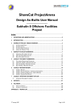
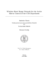
coordinator, a coordinator or a device (Sinem Coleri Ergen, 2004). Figure 1.3
10
shows 3 types of topologies that ZigBee supports: star topology, peer-to-peer
topology and cluster tree.
Figure 2.1 Topology Models
ZigBee devices are often used in mesh network form to transmit data
over longer distances, passing data through intermediate devices to reach more
distant ones. Mesh networking provides high reliability and more extensive
range. This allows ZigBee networks to be formed ad-hoc, with no centralized
control or high-power transmitter/receiver are able to reach all of the devices.
Any ZigBee device can be tasked with running the network (Oziel Hernandez,
Varun Jain, Suhas Chakravarty, Prashant Bhargava, 2010).
11
ZigBee and IEEE 802.15.4
ZigBee technology is a low data rate, low power consumption, low cost;
wireless networking protocol targeted towards automation and remote control
applications. IEEE 802.15.4 committee started working on a low data rate
standard a short while later. Then the ZigBee Alliance and the IEEE decided to
join forces and ZigBee is the commercial name for this technology.
ZigBee is expected to provide low cost and low power connectivity for
equipment that needs battery life as long as several months to several years but
does not require data transfer rates as high as those enabled by Bluetooth. In
addition, ZigBee can be implemented in mesh networks larger than is possible
with Bluetooth. ZigBee compliant wireless devices are expected to transmit 1075 meters, depending on the RF environment and the power output
consumption required for a given application, and will operate in the unlicensed
RF worldwide (2.4GHz global, 915MHz Americas or 868 MHz Europe). The data
rate is 250kbps at 2.4GHz, 40kbps at 915MHz and 20kbps at 868MHz (Sinem
Coleri Ergen, 2004).
IEEE and ZigBee Alliance have been working closely to specify the entire
protocol stack. IEEE 802.15.4 focuses on the specification of the lower two
layers of the protocol (physical and data link layer). On the other hand, ZigBee
Alliance aims to provide the upper layers of the protocol stack (from network to
the application layer) for interoperable data networking, security services and a
range of wireless home and building control solutions, provide interoperability
12
compliance testing, marketing of the standard, advanced engineering for the
evolution of the standard (Sinem Coleri Ergen, 2004).
Microcontroller
Microcontroller is an integrated circuit that has a central processing unit,
input/output interfaces, and peripherals such as timers, RAM, ROM, and a clock
generator. PIC (Peripheral Interface Controller) is a family of modified Harvard
architecture microcontrollers made by Microchip Technology. PICs are popular
with both industrial developers and hobbyists alike due to their low cost, wide
availability, large user base, extensive collection of application notes, availability
of low cost or free development tools, and serial programming (and reprogramming with flash memory) capability. One of the most useful features of
a PIC microcontroller is that one can re-program it as it uses flash memory. One
can either program a PIC microcontroller using an assembler or a high level
language. PICs have a set of registers that function as general purpose RAM.
Special purpose control registers for on-chip hardware resources are also
mapped into the data space. ICSP (In Circuit Serial Programming) is the next
most important benefit. Instead of transferring the chip from the programmer to
the development board just leave it in the board. One can re-program the
device while it's still in the circuit so once the programmer is setup you can
leave it on the bench and test the programs without moving the chip around
and it makes the whole process much easier.
13
The microcontroller executes the program loaded in its flash memory.
This is the so called executable code that comprised of seemingly meaningless
sequence of zeros and ones. It is organized in 12-, 14- or 16-bit wide words,
depending on the microcontroller‟s architecture. Every word is considered by the
CPU as a command being executed during the operation of the microcontroller
(Milan Verle, 2009).
As the process of writing executable code was endlessly tiring, the first
„higher‟ programming language called assembly language was created. The
truth is that it made the process of programming more complicated, but on the
other hand the process of writing program stopped being a nightmare.
Instructions in assembly language are represented in the form of meaningful
abbreviations, and the process of their compiling into executable code is left
over to a special program on a PC called compiler. The main advantage of this
programming
language is its simplicity, i.e. each program instruction
corresponds to one memory location in the microcontroller. It enables a
complete control of what is going on within the chip, thus making this language
commonly used today (Milan Verle, 2009).
However, programmers have always needed a programming language
close to the language being used in everyday life. As a result, the higher
programming languages have been created. One of them is C. The main
advantage of these languages is simplicity of program writing. It is no longer
possible to know exactly how each command executes, but it is no longer of
14
interest anyway. In case it is, a sequence written in assembly language can
always be inserted in the program, thus enabling it (Milan Verle, 2009).
PIC microcontrollers can be programmed in assembly, C or a combination
of the two. Other high-level programming languages can be used but embedded
systems software is primarily written in C (Yesu Thommandru, 2006). Although
assembler is a common choice when programming small microcontrollers, it is
less appropriate for complex applications on larger MCUs; it can become
unwieldy and difficult to maintain as programs grow longer.
A number of
higher-level languages are used in embedded systems development, including
BASIC, Forth and even Pascal.
But the most commonly used “high level”
language is C (David Meiklejohn, 2008).
Previous
wireless
sewer
monitoring
studies
used
Zigbee
for
communication and acoustic sensor technologies to monitor the water level.
Another previous study used remote controlled robots with attached ultrasound
sensors to monitor the sewer. Both of these used audio sensors to monitor the
water level. The use of water level sensor, together with ZigBee has not been
done for sewer monitoring. The study aims to design a sewer/drainage
monitoring system using ZigBee and water level sensors.
15
Chapter 3
DESIGN PROCEDURES
The operation of the proposed active ZigBee based wireless sensor
network for monitoring of drainage is to monitor the drainage condition for an
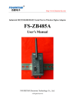
early flood response. Figures 3.1 and 3.2 illustrate the block diagram of the
water level sensor and the main server part of the design project, respectively.
Figure 3.1 Block diagram of water level sensor
In Figure 3.1, the ZigBee will be programmed to act as a wireless
personal network in which data will be sent to the main server wirelessly. The
liquid level sensors will be programmed to monitor and to determine the water
level condition inside the drainage. The liquid level sensors are positioned
vertically to each other with certain distances - on the top, in the center, and
below the acrylic container. They represent the water level condition in the
drainage – high, medium, and low. Microcontroller will be used in order for the
16
ZigBee to interpret the data given by the liquid level sensors and to send it
wirelessly from the water sensor to the PC server and vice-versa.
Figure 3.2 Block diagram of the PC server
Figure 3.2 shows the main server‟s ZigBee is programmed to be the
network coordinator and to receive the data coming from the water level sensor.
The microcontroller will be programmed to interpret the data coming from the
ZigBee and to pass in to the main server. The server will have a program coded
using Microsoft Visual Basic that is responsible for processing the data and
displays it in its graphical user interface. Since the network is connected using
mesh networking, only one ZigBee will be assigned as the coordinator and every
other one will just have to transmit the data until it reaches it. While Figure 3.3
shows the schematic diagram of the components used in the system.
17
X1
R1
C1
22pF
22pF
U1
13
14
OSC1/CLKIN
OSC2/CLKOUT
2
3
4
5
6
7
J1
1
2
3
4
5
RB0/INT
RB1
RB2
RB3/PGM
RB4
RB5
RB6/PGC
RB7/PGD
RA0/AN0
RA1/AN1
RA2/AN2/VREF-/CVREF
RA3/AN3/VREF+
RA4/T0CKI/C1OUT
RA5/AN4/SS/C2OUT
RC0/T1OSO/T1CKI
RE0/AN5/RD
RC1/T1OSI/CCP2
RE1/AN6/WR
RC2/CCP1
RE2/AN7/CS
RC3/SCK/SCL
RC4/SDI/SDA
MCLR/Vpp/THV
RC5/SDO
RC6/TX/CK
RC7/RX/DT
8
9
10
1
RD0/PSP0
RD1/PSP1
RD2/PSP2
RD3/PSP3
RD4/PSP4
RD5/PSP5
RD6/PSP6
RD7/PSP7
CONN-SIL5
SW1
J4
1
2
3
4
5
10k
1
33
34
35
36
37
38
39
40
15
16
17
18
23
24
25
26
19
20
21
22
27
28
29
30
CONN-SIL5
R8
R9
10k
10k
D1
A
R11 Q2
10k
Q1
4
D2
VI
VO
3
A
GND
CONN-SIL2
1
C5
3.3k
J5
C6
C3
1uF
1uF
CONN-SIL3
1
2
3
4
5
6
7
8
9
R4
1k
D4
K
RT9163-33PG
2
Vout
R5
1k
Data
Ground
Run
Vcc
Net
Rx1
Alarm
Tx1
Sleep
Signal Ground
485CTL
Tx2
Center
Rx2
Device
Center Node
Config
Reset
SZ05-ZIGBEE
18
17
16
15
14
13
12
11
10
J2
1
2
CONN-SIL2
1
C4
C7
1uF
1uF
3
2
1
Gnd
LED
Vin
1
2
3
IC1
LED
3
J7
Rx
Tx
1k
K
A
1
2
3
R3
D3
A
U2
J6
CONN-SIL3
K
LED
2
1uF
CONN-SIL3
R7
1
2
3
7805
6
SW-DPDT-MOM
2N2222
2N2222
PIC16F877A
5
1
2
1k
2.2k
10k
3
J10
R2
R10
2
U3
K
LED
R6
J8
3
2
1
CRYSTAL
C2
J9
CONN-SIL3 CONN-SIL3
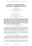
Figure 3.3 Schematic diagram
The schematic diagram has different parts in which the PIC 16F877A
serves as the main part of the system. The PIC 16F877A is the microcontroller
unit (MCU) where it controls the function of the system when sending data
through the ZigBee. The J1 connector is where the water level sensor is placed
in which it will send a string of numbers when it is activated. The transistor acts
as a substitute to the crystal oscillator in which it increases the frequency/signal
of the microcontroller. When the J10 connector (which is a switch) is triggered
the circuit becomes operational. When the sensor is activated it will send a
signal to the microcontroller, then sends a string data to the J4 connector which
is the ZigBee. The ZigBee will then send that string data wirelessly.
18
The software will be coded using Microsoft Visual Basic. It will have a
graphical user interface for controls and data output. Figure 3.4 illustrates the
program flowchart.
Start
Check if “high” Water level
sensor detects water
Water
detecte
d?
Y
Output “High”
N
Check if “medium” Water
level sensor detects water
Water
detecte
d?
Y
Output “Medium”
N
Check if “low” Water level
sensor detects water
Water
detecte
d?
Y
Output “low”
N
Output none
End
Figure 3.4 Program flowchart
19
The component that will represent the drainage tube is a container made
in acrylic in which the liquid level sensors will be placed. The liquid level sensor
returns only discrete values – “0”when it detects any kind of liquid substance
and “1” otherwise. This returned data will then be processed by the PIC
microcontroller unit. The liquid level sensors obtain its power source from the
PIC microcontroller unit. The PIC microcontroller is then powered by an external
power source. The ZigBee is used in creating a wireless personal network that
allows data to be transmitted from one point to another until it reaches the
ZigBee coordinator.
20
Chapter 4
TESTING, PRESENTATION, AND INTERPRETATION OF DATA
Sensor Accuracy Testing
The water level sensor has its own sets of conditions to work; it should
be able to touch water for it to function. In this test, the sensor will be blocked
by materials that affect the sensor‟s reading ability. Each test will have three
sets of trials in which it will determine if the three sensors are able to function
correctly despite the obstacle. The first test will have no barrier for the sensor;
the water level should be filled enough to touch the three sensors and each of
them should be able to detect the water. The procedure for the remaining tests
will be the same as the first one. The only difference is each of the remaining
tests has different barriers for the sensors. If a sensor is broken, it should
output „sensor error‟ instead of not outputting any result. Table 4.1 shows the
results of the sensor accuracy testing.
Table 4.1 Sensor Accuracy Testing
Sensor Reading
Test
Barrier
1
No barrier
2
LOW
MID
HIGH
YES
YES
YES
Paper
YES
YES
YES
3
Bottle
NO
NO
NO
4
Plastic
NO
NO
NO
21
Based on the results, if there is no barrier the sensor is able to easily
detect the water and no problems are encountered. The material is able to read
the paper because the water can pass through the paper. Also the reading of
the sensor depends on the thickness of the paper, when water can't pass
through the paper there will no reading in the sensor. When there is a barrier
like bottle, or plastic material, the sensor is not able to read anything. The
reason is because the sensor needs to touch the water for it to have a reading.
The sensor works when the water is touching it. The sensor is activated by the
reflection of the water coming from its photo diode reading. So, any barrier
facing the sensor will affect its reading or there will be no reading at all.
Signal Integrity Testing
ZigBee
modules
have
different
maximum
range
based
on
its
manufacturer data sheet. This test will determine the maximum range of the
ZigBee module having barriers and obstacles along its way. The tests to be
conducted will be systematic where each will have three trials, and each having
a different test condition. The first test is with no obstruction - the maximum
range will be measured when there is no obstruction present. The following
tests which will have obstructions will be tested and the maximum range will be
determined. The obstructions to be tested for the system are glass, enclosed
room, drawer, and door. Table 4.2 shows the result of the signal integrity
testing.
22
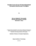
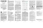
Table 4.2 Signal Integrity Testing
Maximum Range
Test
Container
Trial 1
Trial 2
Trial 3
1
No obstruction
49M
52M
50M
2
Glass Panel
48M
46M
49M
3
Enclose Room
30M
27M
25M
4
Steel
25M
28M
26M
5
Door
29M
25M
27M
60
50
40
No obstruction
Glass Panel
30
Steel
Door
20
Enclosed room
10
0
Trial 1
Trial2
Trial 3
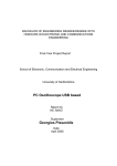
Figure 4.1 Graphical representation of the signal integrity test
Figure 4.1 illustrates the graphical representation of the signal integrity
testing. The data is collected by measuring the maximum distance of the two
ZigBee modules. The measurement is done manually using a measuring tape
where this measures the end-to-end distance between the two modules. Based
23
on the results, the maximum range of the ZigBee can be achieved when there is
no obstruction. For those with obstruction, the glass panel has the strongest
range, meaning that the signal of the ZigBee can easily pass through the glass
panel. The other obstructions have the same or close values because the signal
is not able to pass through easily to those obstructions. The enclosed room have
the weakest range because the ZigBee signal is greatly affected by the
surrounding concrete and steel.
24
Chapter 5
CONCLUSION AND RECOMMENDATION
Conclusion
Monitoring drainage systems conditions remotely provide an easier, safe
and efficient way of monitoring. In this design the researchers are able to
present a wireless sensor network for monitoring of water level in the drainage
systems using ZigBee. The system is capable of monitoring the water level in
drainage systems remotely through the use of ZigBee. The designers approach
in monitoring the drainage conditions is through the use of water level sensors
which are read as low, middle, and high by the corresponding program done in
VB.Net. Test simulations on the design show the effective range of the system
to its remote server and the accuracy of reading of the sensors. The system
implements the wireless network using ZigBee modules because of its efficiency
and low power consumption.
Recommendation
It is recommended that additional study on how fast the water level
increases and decreases from point A to point B. The flow of water should be
determined using a flow sensor to determine how fast the flow of water is in the
drainage pipe. The design should be a networked system where ZigBees and
sensors are positioned and are placed in different drainages to improve
monitoring of the water level in a drainage pipe. To improve the system, the use
25
of branch prediction will address the problem in determining how fast the water
level increases and decreases. Also, an SMS notification maybe included in the
system, to inform and to serve as warning to the public
26
BIBLIOGRAPHY
C.H. See, K.V. Horoshenkov, S.J. Tait, R.A. Abd-Alhameed, Y.F. Hu,
E.A.Elkhazmi and J.G.Gardiner (2009). A Zigbee Based Wireless Sensor Network
for Sewerage Monitoring.
A.K. Shrivastava, A. Verma, S.P. Singh (2012). Development of Robotic
Sewerage Blockage Detector Controlled by Embedded Systems.
Deeter Electronics (2008). Float Level Sensors,
http://www.deeterelectronicsinc.com
Cauligi S. Raghavendra, Krishna M. Sivalingam, and Taieb Znati (2008). Wireless
Sensor Networks.
OFWAT (2007-08). Service and Delivery performance of the Water Companies in
England and Wales Report,
http://www.ofwat.gov.uk/regulating/reporting/rpt_los_2007-08.pdf
Ruan Qiang, Xu Wengsheng, Wang Gaoxiang, 2011. RFID and ZigBee Based
Manufacturing Monitoring System.
Sinem Coleri Ergen, 2004. ZigBee/IEEE 802.15.4 Summary,
https://www.kth.se/social/upload/51041879f276543ad5d03c82/zigbee.pdf
Margaret Rouse, 2006. Definition of ZigBee,
http://searchmobilecomputing.techtarget.com/definition/ZigBee
Oziel Hernandez, Varun Jain, Suhas Chakravarty and Prashant Bhargava, 2010.
Position Location Monitoring using IEEE 802.15.4/ZigBee technology.
27
APPENDIX A
OPERATION’S MANUAL
28
1. System Requirements
The computer must meet these requirements to fully operate the system.
Operating System
Windows XP, Windows Vista, Windows 7
Processor
1.6 Ghz Pentium D
RAM
512 MB, 1GB of RAM recommended
Disk Space
80GB Hard Drive or more
2. Installation Procedure
Hardware
The hardware is composed of the liquid sensors and the wireless
module. The liquid sensors are placed inside the drainage accordingly.
The wireless module connected to them should be placed in a safe and
secured place. It is recommended to minimize obstruction for the
antenna signal and to put in a place away from the water.
The wireless modules should be at least 30 meters from each
other. The central wireless module is attached to the PC server via the
serial to USB cable. Each wireless module (except the central module) is
supplied by a 9V battery.
Software
For the software, the entire files to be implemented are located in
a single folder. The folder is to be placed in a desired location. It is
recommended
to
place
this
folder
in
the
“C:/Program
Files”
location.
29
3. User’s Manual
Getting Started
1. Connect the Serial to USB cable to the wireless module and the PC
server.
2. Start the software by executing the Wireless Drainage Monitoring
application.
3. Press the “Start Acquisition” button to connect the wireless module
and the PC server.
4. Press the “Start Monitoring” button to start the monitoring of water
level. One can enter the desired time of interval for each level output
in the “Time Interval” text box provided.
5. If a log file is desired to be created make sure to provide a name and
press the “Create Log and File” before pressing the “Start Monitoring”
button.
6. To stop the system from monitoring, press the “Stop Monitoring”
button. To disconnect the PC from the wireless module, press the
“STOP” button.
7. To check the status of the sensor, press the “Check Sensors” button.
(Must stop the monitoring first)
8. To close the program, press “Disconnect and Exit”.
30
User Interface
1. Serial Port Box – shows available ports to be used.
2. Start Acquisition Button – connects the wireless module and the PC
server via the serial port selected.
3. STOP Button – stops the system from monitoring and disconnects the
currently connected port.
4. Sensor Status – Outputs the current status of the sensor (i.e. low,
medium, high).
5. Logger – displays and logs the output data of the liquid level sensors.
6. Time Interval – queries for the program and outputs the data from
the liquid level sensors.
31
7. Start Monitoring Button – starts the monitoring of the water level of
the program. The port and the PC must be connected first before one
can start monitoring.
8. Stop Monitoring Button – stops the monitoring of the water level of
the program.
9. Check Sensors Button – checks the current status of the water sensor;
must stop monitoring first before you can check.
10. Log File Name – file name of the log file one wants to be created.
11. Create File and Log – creates the log file and starts logging the
output data of the program into the log file.
12. Disconnect and Exit – disconnects the wireless module and PC server,
then closes the program.
4. Troubleshooting Guides and Procedures
A. If start acquisition button returns and error, make sure first that the
cable is properly connected, and have selected the available port.
B. If no log file is being recorded, make sure that one has selected the
„create file and log‟ button before selecting the „start monitoring‟
button.
C. If there is no or an incorrect output, this may be because some of the
wireless module cannot reach each other. One places the wireless
module at least 50 meters from each other or nearer depending on
how thick the obstruction is.
32
D. If there is still no or incorrect output, check the wireless module if
they are still functioning or replace the battery.
Error Definitions
A. Connect to device first – device must be connected first via „Start
Acquisition‟ button before monitoring starts.
B. Port is closed – device must be connected first via „Start Acquisition‟
button when this error appears.
C. Port already opened – error shows that the device is already
connected when the user is trying to connect it.
D. Stop monitoring first – monitoring must first be disabled when this
error appears.
E. No log file will be created – To enable a log file, one must create it
first via the create log file button.
33
APPENDIX B
DATA SHEETS
34
PIC16F87XA
35
36
37
38
SZ05-ZIGBEE
39
S Z05-ZIGBEEThe wireless communication module user manual
Ⅰ Introduction
The boat SZ05 series of embedded wireless communication module integrated ZigBee
protocol standards radio frequency transceivers and microprocessors. It has the characteristics and
advantages of long communication distance, strong anti-jamming capability, flexible network and
stable performance. Meanwhile, it can achieve point-to-point, multipoint, multi-multipoint
transparent data transfer between devices. And the devices communicate with each other forms the
network of a star, a branching tree or a net (mesh).
SZ05 series of wireless communication module‘s data interfaces including: TTL interface and
RS232 standard interface. They can send the data by way of broadcast or target address. In
addition to achieving the general point-to-point data communication functions, they also can
realize the multipoint communication. What‘s more, the serial communication is so easy and
convenient to use that it can reduce the matching process time of inserting the embedded module.
SZ05 series of wireless communication module is divided into three nodes in the network:
Central Coordinator, Router and End-Device. They have different functions in the network. The
Central Coordinator is the central nodes which can automatically initiate maintain and manage the
information of the network. The Router takes the charge of liking network together, transmitting
the data and associating with other routers and End-devices. And the terminal nodes only send and
receive the data. Central coordinator, a router and terminal node, these three types of devices are
the same in hardware but the embedded software is different. In way of jumpers settings or
software configuration can realize the different functions of devices.
Ⅱ Technical specifications
Category
Index name
SZ05 series wireless module
The transmissio n distance
100 meters - 2,000 meters
Netw ork topolog y
Star, tree and chain type, mesh netw ork
Wireless
IEEE80 2 .15 .4 / ZIGBE E stand ard
network
Addressin g mode
addre ss
Data interfa ce
Network ID
255
Maximu m data packet
256 bytes
Data interfa ce
Serial signal
TTL , RS232 standard interface
TxD, RxD, GND
40
Serial rate
1,200 ~ 38,400 bps
Serial calibra tio n
None, Even, Odd
Data bits,
7, 8
parity
1
Modulatio n mode
The DSSS direct seque nce sprea d
spectrum
Frequency range
2.405 GH z~ 2.480 G H z
Wireless chann el
16
Receiving sensitivity
-94 dbm
Transmission power
-27dBm~25dBm
Antenn a
The outer SMA anten na or PCB anten n a
transceiver
Conflict prevention
power
Working
environment
GTS CSMA - CA and CSMA - CA
Input voltage
DC 5V
Maximum current
70 mA
Maximum receiving current
55 mA
Standby current
10 mA
Power saving mode
110 uA
Sleep pattern
30 uA
Working temperature
-40 C ~ 85 C
Storage temperature
-55 C ~ 125 C
41
Ⅲ Interface
3.1 Module to the left of pin identification
Sequence
Mark
Function
1
GND
Ground
2
+5V
Power input is 5V
3
RX1/TTL
TTL level input
4
TX1/TTL
TTL level output
5
SGND
6
TX2/RS23
2
Serial RS232 output
Connec t the user input 232
7
RX2/RS23
2
Serial RS232 input
Connect the user output 232
Serial RS232 signal
ground
Notes
TX output to connect the user
system
RX input to connect the user system
Ground
42
8
9
RESET
System reserved
Vacant
System reset
LOW Reset
3.2 Module to the right of pin identification
Sequence
Mark
1
DATA
2
RUN
Function
Notes
Sending and receiving
Low light. the data transceiver is
data instructions
flashing
System running light
Low light. interval of 1second flashes
Low light. the center succeeded in
3
NET
Network indicators
building a network node, bright light
from the node to connect the network
4
ALARM
5
SLEEP
6
485CTL
System warning light
Low light
Low power
Low access to low-power, high level or
consumption
normal operation of floating
485 transceiv er control
Low output when the module 485 to
receive. high output when it sent
Low effective or adding the jumper cap
7
CENTER
Center node
becomes a central node. If 7 and 8 are
as high level or floating it is the routing
node.
Low effective or adding the jumper cap
8
DEVI CE
Terminal node
into the terminal nodes. If 7 and 8 are
as high or floating it is the routing node
9
CONFIG
Configur ati on interface
Low effective or adding the jumper cap
into the system configuration state
43
3.3 Module wiring diagram
44
3.4 Module control lines
Pin
Module
Valid state
initialization
User Control
Control state
I / O initialization
DATA
High level 3.3V
Low level
——
——
NET
High level 3.3V
Low level
——
——
RUN
High level 3.3V
Low level
——
——
ALARM
High level 3.3V
Low level
——
——
SLEEP
High level 3.3V
——
High level 3.3V
Low level
485CTL
Low level
——
CENTER
High level 3.3V
Low level
High level 3.3V
Low level
DEVICE
High level 3.3V
Low level
High level 3.3V
Low level
CONFIG
High level 3.3V
Low level
High level 3.3V
RESET
High level 3.3V
Low level
High level 3.3V
Connect the 485
chips controller
——
Low level 3
seconds
Low level
3.5 Power Interface
The standard operating voltage of SZ05-ZBEE wireless communication module is DC-5V. The
normal operating voltage range is from5V to 12V.
Notes: The power of positive and negative can not be reversed. Otherwise they will burn out the
module.
3.6 Data interface
SZ05-ZBEE wireless communication module offers two standard interfaces: RS232 interface and
TTL interface. The working interfaces of serial port RS232 are TX, RX and GND. However, the TTL
working interfaces are TX and RX. And the TTL level is 3.3V.
Serial port parameters
Serial Rate
Default Set
9,600
45
Serial check
None
Data bits
8
Stop bit
1
3.7 Node type configuration
SZ05-ZBEE wireless communication module has three node types: center node, relay routing
node and the terminal node. A short jumper connection is to control the center node, the relay routing
node or the terminal node, if the short jumper is effective, the center node or the terminal node can
be only chosen one. This node will be the relay routing node if the two short jumpers are suspended.
3.8 Configuration interface
If CONFIG jumper shorted or external control line of SZ05-ZBEE wireless communication
module gets into the low level state in 3 seconds, the system will come into the configuration state.
Being high level or floating is the working state. Configuration interface is used for some parameters
to be configured. The default configuration of Serial RS232 is as follows:
Serial port parameters
Default Set
Serial Rate
38,400
Serial check
None
Data bits
8
Stop bit
1
Configuration interface settings
The configuration mode of SZ05-ZBEE wireless communication module can be divided into
super-terminal configuration mode and the computer network management configuration mode. The
state of the two models is classified as follows:
46
Instructions state
Instructions meaning
Data, operation, network and alarm light flicker at
Super- terminal configuration mode
the same time
Computer network management
configuration mode
Alarm light flashes in 1 second interval. Running
lights flashes normally. Data light don‘t flicker.
Super- terminal configuration mode means entering the computer‘s super terminal to do
the module settings.
Computer network management configuration model is the protocol specification which can
provide the system interface for the user to carry on the software integration.
The steps of the Super-terminal configuration mode
1.Open the computer's HyperTerminal and set HyperTerminal as follows: 38400 baud, 8 data
bits, check NONE, stop bits 1, flow control none.
2. CONFIG jumper shorted or external control line comes into the low level.
3. Power to devices.
4. Entering the device configuration mode.
Notes: Being the configuration mode, the serial port is configured: 38400 baud, 8 data bits,
check NONE, stop bit 1. So the computer's serial port settings must be 38400 baud, 8 data bits,
check NONE, stop bit 1, flow control NONE.
Ⅳ Module configuration
Equipment configuration options are as follows:
Configuration options
Chinese options
Configu ration
CHANNE L
A communica tion
channel
Use Netcom channel
NET_TYPE
Network type
NODE_TYP E
Device type
NET_I D
Network ID
TX_TYP E
Sending mode
MAC_AD DR
Device address
DATA_TYP E
Data type
The default
parameters
0x0F
Mesh network
Relay route
Use Netcom number
0xFF
radio
Different device has
different address
——
HEX
47
DATA_BIT
Data bits,
BAUD_R ATE
Baud rate
PARITY
Data validation
TIME_OU T
Serial overtime
SRC_ADDR
Data source address
8
9,600
NONE
0x05 ms
Not output
4.1 Communication channel set
Channel
Configu ration instru ctions
Notes
0 : 2.405G H z
1 : 2.410G H z
2 : 2.415G H z
3 : 2.420G H z
4 : 2.425G H z
5 : 2.430G H z
6 : 2.435G H z
0-F
7 : 2.440G H z
Recommended 4, 9,
8 : 2.445G H z
9 : 2.450G H z
14 or 15 channels,
which can avoid WIFI
A
B
C
D
interference.
: 2.455G Hz
: 2.460G Hz
: 2.465 GH z
: 2.470G H z
E : 2.475 G Hz
F : 2.480 G H z
G
AUTO mode to choose the best channel
4.2 NET_TYPE network type
NET_T Y PE options
Network type
Configuration
notes
MESH
Mesh network
Master-sla ve network and
the network must have
In the same network,
the network type must
STAR
Star nets
only one center node.
be set the same.
48
LINE_1
Chain type nets ID=1
LINE_2
Chain type nets ID=2
LINE_3
Chain type nets ID=3
LINE_4
Chain type nets ID=4
PEER
Peer-to-peer network
Master-slave network
No center node
4.3 NODE_TYPE device type
NODE_TYPE options
PAN_COORD
Network types
Configuration
note
Center node
It has the terminal
equipment functions, too.
ROUTER
Relay route
END_D EV ICE
Terminal equipme nt
There must be a
center node in
the network.
SZ05-ZBEE wireless communication module has three types: the center node, the relay routing
node and the terminal node. A short jumper connection is to control the center node, the relay
routing node or the terminal node, if the short jumper connection is effective, the center node or
the terminal node can be only chosen one. This node will be the relay routing node if the two short
jumpers are suspended.
4.4 The network number NET_ID Settings
NODE_TYPE options
ID range
NET_I D
00—FF
Configuration
notes
The whole network‘s ID
must be the same.
In a network, ENTER NET_ID # 2, then click "setup". ENTER the ENTER
4.5 Data sent TX_TYPE mode Settings
TX_TYPE options
Send mode
Configuration
notes
49
BROADC AST
Broadcast mode
Master-sla ve
MASTE R—SL AV E
mode
No target address
The center node must have target
address. Non-central
nodes If target address is 2
haven‘t target address
and bytes MAC address,
default send the data to the
it must be added
center node.
POINT— P OIN T
peer-to-pee r
before the packet.
Target address must
4.6 Equipment MAC_ADDR address
MAC_ADDR options
ID range
MAC_AD DR
0000—F F FE
Configuration
note
The address of center
node is 0000
The
whole
network
cannot have the same
address nodes.
Input the net 4 device address and then press "ENTER" to finish the setup.
4.7 DATA_TYPE data types
DATA _TY P E options
Data types
ASCII
ASCII
HEX
Hex
Configuration
It must be set if has the target address. If broadcast
way without settings.
4.8 DATA_BIT set
DATA _TY P E options
Data types
7+1+1
7 bit data + 1 check + 1 stop bits
Configuration
To combine with data validation to
set
8+0+1
8 bit data +0 check + 1 stop bits
50
8+1+1
8 bit data +1 check + 1 stop bits
4.9 Serial BAUD_RATE set
BAUD _R A TE options
Baud rate range
Configuration
1,200
1,200-3,8400
Choose match baud rate
38,400
4.10 DATA_PARITY set
DATA_P ARI TY options
Equip ment types
NONE
No calibration
EVEN
Parity checking
ODD
Parity checking
Configu ration
Select the match calibration type
4.11 Serial TIME_OUT set
TIME_O U T option s
TIME_OU T
Equip ment types
1-255ms(
Hexadecimal
display)
notes
Serial overtime time.
4.12 SRC_ADDR data source address set
SRC_A D R options
NOT OUTP U T
Data source address
Configuration
Not output source
address
According to the application to choose whether
to output source address of data packets
HEX
Hexadecimal output
51
ASCII
ASCII output
The formats of Hexadecimal output source address: 2 bytes of data source address + valid data. The
formats of ASCII mode output source address: 4 bytes of data source address +valid data.
Ⅴ Data sending instructions
5.1 Data sending mode
Module type
Send mode
radio
Center node
Goal node
Send mode
All non-central node
Data directly
within the network
Master-sla ve or
Target address node
Target address + data
radio
All non-central node
Data directly
Master-sla ve
Center node
Data directly
peer-to-pee r
Target address node
Target address + data
peer-to-pee r
Non-central
node
5.2 Data transmission frame format
Send mode
Data coding
Do not make any changes
Data directly
Hexadecimal target
Target address +
data
Data frame format
address
ASCII target address
2 bytes target address + data
4 bytes target address + data
52
53
APPENDIX C
PROGRAM LISTING
54
Microcontroller Program
#define MX_PIC
#define MX_USES_UINT8 1
#define MX_USES_SINT16 0
#define MX_USES_CHAR 0
#define MX_USES_FLOAT 0
#define MX_USES_SINT32 0
#define MX_USES_BOOL 1
#define MX_USES_UINT16 0
#define MX_USES_UINT32 0
//Defines for microcontroller
#define P16F877A
#define FC_CAL_PIC
#define MX_ADC
#define MX_ADC_TYPE_1
#define MX_ADC_BITS_10
#define MX_EE
#define MX_EE_TYPE2
#define MX_EE_SIZE 256
#define MX_SPI_1
#define MX_SPI_1_MISO_PORT
portc
#define MX_SPI_1_MISO_TRIS trisc
#define MX_SPI_1_MISO_PIN 4
#define MX_SPI_1_MOSI_PORT
portc
#define MX_SPI_1_MOSI_TRIS trisc
#define MX_SPI_1_MOSI_PIN 5
#define MX_SPI_1_CLK_PORT portc
#define MX_SPI_1_CLK_TRIS trisc
#define MX_SPI_1_CLK_PIN 3
#define MX_SPI_1_SS_PORT portc
#define MX_SPI_1_SS_TRIS trisc
#define MX_UART_1
#define MX_UART_1_TX_PORT portc
#define MX_UART_1_TX_TRIS trisc
#define MX_UART_1_TX_PIN 6
#define MX_UART_1_RX_PORT
portc
#define MX_UART_1_RX_TRIS trisc
#define MX_UART_1_RX_PIN 7
#define MX_I2C
#define MX_MI2C
#define MX_I2C_1
#define MX_I2C_1_SDA_PORT portc
#define MX_I2C_1_SDA_TRIS trisc
#define MX_I2C_1_SDA_PIN 4
#define MX_I2C_1_SCL_PORT portc
#define MX_I2C_1_SCL_TRIS trisc
#define MX_I2C_1_SCL_PIN 3
#define MX_PWM
#define MX_PWM_CNT 2
#define MX_PWM_PSCA1
#define MX_PWM_PSCA4
#define MX_PWM_PSCA16
#define MX_PWM_1_PORT portc
#define MX_PWM_1_TRIS trisc
#define MX_PWM_1_PIN 2
#define MX_PWM_2_PORT portc
#define MX_PWM_2_TRIS trisc
#define MX_PWM_2_PIN 1
//Functions
#define MX_CLK_SPEED 20000000
#ifdef _BOOSTC
#include <system.h>
#endif
#ifdef HI_TECH_C
#include <pic.h>
#endif
//Configuration data
#ifdef _BOOSTC
#pragma DATA 0x2007, 0x3f3a
#endif
#ifdef HI_TECH_C
55
__CONFIG(0x3f3a);
#endif
//Internal functions
#include "D:\Program
Files\Flowcode\v5\FCD\internals.c"
//Macro function declarations
//Variable declarations
#define FCV_FALSE (0)
#define FCV_TRUE (1)
MX_UINT8 FCV_SERIAL_IN;
MX_UINT8 FCV_LEVELSENSORS;
//RS232(0): //Defines:
/**** Macro Substitutions ****
a = Unique Reference
b = Uart Channel (0-software / 1-4
hardware)
c = tx pin
d = tx port
e = rx pin
f = rx port
g = flow control (0-Off / 1-On)
h = cts pin
i = cts port
j = rts pin
k = rts port
l = baud rate
m = data bits (7/8/9) (7 only
supported in software modes)
n = return type (0-byte / 1MX_UINT16)
o = echo enable (0-Off / 1-On)
//Definitions for RS232 UART slot
allocation
#ifndef MX_UART_REF1
#define MX_UART_REF1
#define RS232_1_MX_UART_UREF 1
#define MX_UART_CHANNEL_1 1
#define MX_UART_TX_PIN_1 0
#define MX_UART_TX_PORT_1
porta
#define MX_UART_TX_TRIS_1 trisa
#define MX_UART_RX_PIN_1 0
#define MX_UART_RX_PORT_1
porta
#define MX_UART_RX_TRIS_1 trisa
#define MX_UART_FLOWEN_1 0
#define MX_UART_CTS_PIN_1 4
#define MX_UART_CTS_PORT_1
portc
#define MX_UART_CTS_TRIS_1 trisc
#define MX_UART_RTS_PIN_1 0
#define MX_UART_RTS_PORT_1
portc
#define MX_UART_RTS_TRIS_1 trisc
#define MX_UART_BAUD_1 9600
#define MX_UART_DBITS_1 8
#define MX_UART_RETURN_1 0
#define MX_UART_ECHO_1 0
#define MX_UART_INT_1 0
#else
#ifndef MX_UART_REF2
#define MX_UART_REF2
#define RS232_1_MX_UART_UREF 2
#define MX_UART_CHANNEL_2 1
#define MX_UART_TX_PIN_2 0
#define MX_UART_TX_PORT_2
porta
#define MX_UART_TX_TRIS_2 trisa
#define MX_UART_RX_PIN_2 0
#define MX_UART_RX_PORT_2
porta
#define MX_UART_RX_TRIS_2 trisa
#define MX_UART_FLOWEN_2 0
56
#define MX_UART_CTS_PIN_2 4
#define MX_UART_CTS_PORT_2
portc
#define MX_UART_CTS_TRIS_2 trisc
#define MX_UART_RTS_PIN_2 0
#define MX_UART_RTS_PORT_2
portc
#define MX_UART_RTS_TRIS_2 trisc
#define MX_UART_BAUD_2 9600
#define MX_UART_DBITS_2 8
#define MX_UART_RETURN_2 0
#define MX_UART_ECHO_2 0
#define MX_UART_INT_2 0
#else
#ifndef MX_UART_REF3
#define MX_UART_REF3
#define RS232_1_MX_UART_UREF 3
#define MX_UART_CHANNEL_3 1
#define MX_UART_TX_PIN_3 0
#define MX_UART_TX_PORT_3
porta
#define MX_UART_TX_TRIS_3 trisa
#define MX_UART_RX_PIN_3 0
#define MX_UART_RX_PORT_3
porta
#define MX_UART_RX_TRIS_3 trisa
#define MX_UART_FLOWEN_3 0
#define MX_UART_CTS_PIN_3 4
#define MX_UART_CTS_PORT_3
portc
#define MX_UART_CTS_TRIS_3 trisc
#define MX_UART_RTS_PIN_3 0
#define MX_UART_RTS_PORT_3
portc
#define MX_UART_RTS_TRIS_3 trisc
#define MX_UART_BAUD_3 9600
#define MX_UART_DBITS_3 8
#define MX_UART_RETURN_3 0
#define MX_UART_ECHO_3 0
#define MX_UART_INT_3 0
#else
#ifndef MX_UART_REF4
#define MX_UART_REF4
#define RS232_1_MX_UART_UREF 4
#define MX_UART_CHANNEL_4 1
#define MX_UART_TX_PIN_4 0
#define MX_UART_TX_PORT_4
porta
#define MX_UART_TX_TRIS_4 trisa
#define MX_UART_RX_PIN_4 0
#define MX_UART_RX_PORT_4
porta
#define MX_UART_RX_TRIS_4 trisa
#define MX_UART_FLOWEN_4 0
#define MX_UART_CTS_PIN_4 4
#define MX_UART_CTS_PORT_4
portc
#define MX_UART_CTS_TRIS_4 trisc
#define MX_UART_RTS_PIN_4 0
#define MX_UART_RTS_PORT_4
portc
#define MX_UART_RTS_TRIS_4 trisc
#define MX_UART_BAUD_4 9600
#define MX_UART_DBITS_4 8
#define MX_UART_RETURN_4 0
#define MX_UART_ECHO_4 0
#define MX_UART_INT_4 0
#endif
#endif
#endif
#endif
#define RS232_1_UART_Init
CAL_APPEND(FC_CAL_UART_Init_,
RS232_1_MX_UART_UREF)
#define RS232_1_UART_Send
CAL_APPEND(FC_CAL_UART_Send_,
RS232_1_MX_UART_UREF)
57
#define RS232_1_UART_Receive
CAL_APPEND(FC_CAL_UART_Receiv
e_, RS232_1_MX_UART_UREF)
#define
RS232_1_UART_Update_Baud
CAL_APPEND(FC_CAL_UART_Update
_Baud_, RS232_1_MX_UART_UREF)
extern void RS232_1_UART_Init();
extern void
RS232_1_UART_Send(MX_UINT16
nChar);
extern MX_SINT16
RS232_1_UART_Receive(MX_UINT8
nTimeout);
extern void
RS232_1_UART_Update_Baud(MX_U
INT8 newbaud);
void
FCD_RS2320_ChangeHWBaud(MX_U
INT8 newbaud);
//RS232(0): //Macro
implementations
void
FCD_RS2320_SendRS232Char(MX_S
INT16 nChar)
{
RS232_1_UART_Send (
nChar);
}
//RS232(0): //Macro function
declarations
void
FCD_RS2320_SendRS232Char(MX_S
INT16 nChar);
void
FCD_RS2320_SendRS232String(MX_
STRING String, MX_UINT8
MSZ_String);
MX_SINT16
FCD_RS2320_ReceiveRS232Char(MX
_UINT8 nTimeout);
void
FCD_RS2320_ReceiveRS232String(M
X_CHAR* FCR_RETVAL, MX_UINT8
FCR_RETVAL_SIZE, MX_UINT8
nTimeout, MX_UINT8 NumBytes);
void
FCD_RS2320_SendRS232String(MX_
STRING String, MX_UINT8
MSZ_String)
{
MX_UINT8 idx;
for(idx = 0; idx <
MSZ_String; idx++)
{
if (String[idx] == 0)
break;
else RS232_1_UART_Send (
String[idx] );
}
}
MX_SINT16
FCD_RS2320_ReceiveRS232Char(MX
_UINT8 nTimeout)
58
{
return ( RS232_1_UART_Receive (
nTimeout) );
}
void
FCD_RS2320_ReceiveRS232String(M
X_CHAR* FCR_RETVAL, MX_UINT8
FCR_RETVAL_SIZE, MX_UINT8
nTimeout, MX_UINT8 NumBytes)
{
MX_UINT8 idx;
MX_SINT16 RS232_TO = 255;
MX_SINT16 in;
if ( 0 != 0 )
FCR_RETVAL[idx] = 0;
}
void
FCD_RS2320_ChangeHWBaud(MX_U
INT8 newbaud)
{
RS232_1_UART_Update_Baud
(newbaud);
}
#include "D:\Program
Files\Flowcode\v5\CAL\includes.c"
//Macro implementations
RS232_TO =
256;
if (NumBytes >
FCR_RETVAL_SIZE)
NumBytes =
FCR_RETVAL_SIZE;
void main()
{
//Initialization
adcon1 = 0x07;
RS232_1_UART_Init( );
//Call initialise function
for (idx = 0; idx < NumBytes;
idx++)
{
in = RS232_1_UART_Receive
( nTimeout);
if(in < RS232_TO)
//Interrupt initialization code
option_reg = 0xC0;
//Comment:
//Enable MCU led indicator
FCR_RETVAL[idx] = in &
//Output
//Output: 1 -> B0
trisb = trisb & 0xFE;
if ((1))
portb = (portb & 0xFE) |
0xFF;
else
break;
}
0x01;
if (idx < FCR_RETVAL_SIZE)
else
portb = portb & 0xFE;
59
//Comment:
//if sensor value is
//00 = high
//04 = middle
//06 = low
//07 = no water
//for everything else is sensor
error
//Loop
//Loop: While 1
while (1)
{
//Call Component
Macro
//Call Component
Macro:
Serial_in=ReceiveRS232Char(10)
FCV_SERIAL_IN =
FCD_RS2320_ReceiveRS232Char(10)
;
//Decision
//Decision: Serial_in =
0x31?
if (FCV_SERIAL_IN ==
0x31)
{
//Input
//Input: PORTA
-> LevelSensors
trisa = trisa |
0x07;
FCV_LEVELSENSORS = porta
& 0x07;
//Switch
//Switch: LevelSensors?
switch (FCV_LEVELSENSORS)
{
case 00:
{
//Call Component Macro
//Call Component Macro:
SendRS232String("High")
FCD_RS2320_SendRS232Strin
g("High", 4);
break;
}
case 04:
{
//Call Component Macro
//Call Component Macro:
SendRS232String("Middle")
FCD_RS2320_SendRS232Strin
g("Middle", 6);
break;
}
case 06:
{
//Call Component Macro
//Call Component Macro:
SendRS232String("Low")
FCD_RS2320_SendRS232Strin
g("Low", 3);
break;
}
case 07:
{
//Call Component Macro
60
//Call Component Macro:
SendRS232String("Empty")
FCD_RS2320_SendRS232Strin
g("Empty", 5);
break;
}
default:
{
//Call Component Macro
//Call Component Macro:
SendRS232String("Sensor Error")
FCD_RS2320_SendRS232Strin
g("Sensor Error", 12);
}
}
//Output
//Output: 1 -> B0
trisb = trisb & 0xFE;
if ((1))
portb = (portb & 0xFE) | 0x01;
else
portb = portb & 0xFE;
// } else {
}
}
mainendloop: goto mainendloop;
}
void MX_INTERRUPT_MACRO(void)
{
}
//Call Component Macro
//Call Component Macro:
SendRS232Char(13)
FCD_RS2320_SendRS232Char
(13);
//Output
//Output: 0 -> B0
trisb = trisb & 0xFE;
if ((0))
portb = (portb & 0xFE) |
0x01;
else
portb = portb & 0xFE;
//Delay
//Delay: 100 ms
delay_ms(100);
61
Visual Basic Program
Imports System
Imports System.IO.Ports 'Required to get the port strings
Imports System.IO
Public Class DrainageMonitor
' Declare public variables
Dim StringSerial As String
Dim PortOpenStatus As Boolean = 0
Dim Filename1 As String
Dim Nofile As Boolean = 0
Private Declare Sub Sleep Lib "kernel32" (ByVal dwMilliseconds As Long) 'Get
msdelay
' ----------- DROP DOWN SELECTION FOR PORTS ----------Private Sub cbxPortName_DropDown(ByVal sender As Object, ByVal e As
System.EventArgs) Handles cbxPortName.DropDown
cbxPortName.Items.Clear() 'Reset/clear port list before checking ports. So
that it won't just append.
Dim ports As String() = SerialPort.GetPortNames() 'Get all available ports
and place in a 1-dimentional array
'Go through each of the available ports and place them in the dropdown
For Each portName In ports
cbxPortName.Items.Add(portName)
Next
End Sub
' ----------- START AQUISITION BUTTON ----------Private Sub BtnOpenPort_Click(ByVal sender As System.Object, ByVal e As
System.EventArgs) Handles BtnOpenPort.Click
'Enables serial port to be opened.
If PortOpenStatus = 0 Then 'If off(0) then it will turn in on on(1)
62
SerialPort1.PortName = cbxPortName.SelectedItem.ToString()
SerialPort1.Open()
SerialPort1.DiscardInBuffer() 'clear buffer
Timer1.Enabled = True
PortOpenStatus = 1
SerialPort1.Write("A")
Else
MsgBox("Port already open!") 'if port was already opened and user tried
to opened it again.
End If
End Sub
' ----------- E-STOP BUTTON ----------Private Sub Button2_Click(ByVal sender As System.Object, ByVal e As
System.EventArgs) Handles Button2.Click
If SerialPort1.IsOpen = True Then
SerialPort1.Write("B") 'Turns OFF Relay
SerialPort1.Close()
Timer1.Enabled = False
PortOpenStatus = 0
MsgBox("STOP PRESSED!!") 'Alert the user that the stop has been
pressed
Else
MsgBox("Port Closed")
End If
End Sub
' --------------- START MONITORING BUTTON --------------Private Sub Button4_Click(ByVal sender As System.Object, ByVal e As
System.EventArgs) Handles Button4.Click
If Timer1.Enabled = True Then
Timer2.Interval = TbxTimerInterval.Text 'Get the interval from the
interval input box
63
Timer2.Enabled = True
If Nofile = False Then
MsgBox("No log file will be created.") 'If there was no log file created
initially
End If
Else
MsgBox("Connect To device first") 'Must press "Start Aquisition' first!
End If
End Sub
' --------------- STOP MONITORING BUTTON --------------Private Sub Button5_Click(ByVal sender As System.Object, ByVal e As
System.EventArgs) Handles Button5.Click
Timer2.Enabled = False 'Disable timer2
TbxFilename.Text = "" 'Clear the log file text box after pressing "Stop
Monitoring"
End Sub
' --------------- CHECK SENSOR BUTTON --------------Private Sub Button1_Click_1(ByVal sender As System.Object, ByVal e As
System.EventArgs) Handles Button1.Click
If Timer2.Enabled = True Then
MsgBox("Stop Monitoring first!") 'Must stop monitoring first before you
can check sensor status
Else
If SerialPort1.IsOpen = True Then
SerialPort1.Write("1") 'Writes 1 to the port to verify it is detected
Else
MsgBox("Port is Closed!") 'If port is closed, alert the user
End If
End If
End Sub
' --------------- CREATE LOG FILE BUTTON --------------64
Private Sub Button6_Click(ByVal sender As System.Object, ByVal e As
System.EventArgs) Handles Button6.Click
Filename1 = TbxFilename.Text 'Get the filename of the file to be created
Filename1 = "C:\" + Filename1 + ".Txt" 'Save the log file at this location
Using writer As StreamWriter = New StreamWriter(Filename1) 'Initialize
streamwriter
Nofile = True 'true, meaning log file is created
MsgBox("file created at " + Filename1) 'alert the user of the location of
the created log file
End Using
End Sub
' --------------- DISCONNECT AND EXIT BUTTON --------------Private Sub Button3_Click(ByVal sender As System.Object, ByVal e As
System.EventArgs) Handles Button3.Click
'Disconnect the port
If SerialPort1.IsOpen = True Then
SerialPort1.Write("B") ' Turns OFF Relay
SerialPort1.Close()
Timer1.Enabled = False
PortOpenStatus = 0
End If
End 'Exit program
End Sub
' --------------- CHECK SENSOR BUTTON --------------' Outputs sensor status in the tbxRawData
Private Sub Button1_Click(ByVal sender As System.Object, ByVal e As
System.EventArgs)
Dim buffersize As Integer
buffersize = SerialPort1.BytesToRead
65
tbxRawData.Text = buffersize 'Outputs the sensor status in the "Sensor
Status" text box
End Sub
' --------------- WRITE TO LOG BOX ---------------Private Sub Timer1_Tick(ByVal sender As System.Object, ByVal e As
System.EventArgs) Handles Timer1.Tick
Dim buffersize As Integer
buffersize = SerialPort1.BytesToRead
If buffersize > 0 Then
StringSerial = SerialPort1.ReadExisting 'Read the port data
tbxRawData.Text = StringSerial 'Output the port string data
TbxLogger.Text = DateString + "," + TimeOfDay + "," +
tbxRawData.Text + vbCrLf + TbxLogger.Text 'Output to logger box
If TbxFilename.Text = "" Then
Nofile = False 'If logfile input box is empty, no log file will be created
Else
'If log file was created, write the contents of the logger box to the log
file
If Nofile = True Then
Using writer A s StreamWriter = New StreamWriter(Filename1,
True)
writer.WriteLine(DateString + "," + TimeOfDay + "," +
tbxRawData.Text)
End Using
End If
End If
End If
End Sub
' --------------- TIMER2 -------------Private Sub Timer2_Tick(ByVal sender As System.Object, ByVal e As
System.EventArgs) Handles Timer2.Tick
66
' Check the port at timer2 interval
If SerialPort1.IsOpen = True Then
SerialPort1.Write("1") 'Writes 1 to the port to verify that the port is still
opened
Else
MsgBox("Port is closed!") 'Alerts the user if the port was disconnected
End If
End Sub
End Class
67
APPENDIX D
PICTURES OF PROTOTYPE
68
69
70
APPENDIX E
71
A Wireless Sensor Network for Monitoring of
Water Level on Drainage Systems using ZigBee
Ani, Meynard Frizth A.
Chua, Divina A.
Cuna, Michael John A.
Abstract - Clogged drainage systems are the
major cause of pollution and frequent flooding in
Metro Manila especially during the rainy season.
Thus, it is required to routinely monitor the
condition of these drainage systems. The
proposed system provides a way to monitor
remotely drainage conditions and inform
authorities of these conditions. This design
presents an implementation of wireless sensor
network in the monitoring of drainage systems
using ZigBee. The use of ZigBee in wireless
sensor network provides low cost, low power
consumption, flexible and reliable network
which is fast and easy to deploy. Blockages in
drainage systems are detected through
monitoring of water levels inside the drainage.
The design consists of water level sensors which
read the water levels and the ZigBee module is
used to wirelessly send this information back to a
central computer that monitors all drainages
throughout the area.
Keywords: drainage systems, monitoring,
wireless sensor network, ZigBee, water level
I. INTRODUCTION
Clogging of drainage is a major cause of both
flooding and pollution in Metro Manila.
Flooding is one of the main problems in the
metro. This problem can result to even bigger
disasters, such as deaths and damage to
properties. Hence, providing an early warning
device is one of the measures to prevent such
disasters. The detection of drainage condition is
routinely required in order to be informed on the
best course of action that provides a solution to
this critical problem. According to the Metro
Manila Development Authority (MMDA),
drainage and sewerage functions are combined in
other countries unlike here in the Philippines
where it is separate. The sewerage handles
human waste and other liquid waste coming
from households, while the drainage handles
liquid waste coming from streets, factories,
creeks, etc. This design project is based on the
areas being handled by the MMDA.
Some of the existing systems today are for flood
detection and control. This proposed system is
focused more towards prevention rather than
control. In the article ―Development of Robotic
Sewerage Blockage Detector Controlled by
Embedded Systems‖ (Shrivastava, 2012), a
remote controlled robot is attached with sensors
for monitoring blockages in sewer pipelines.
They used ultrasound sensors to detect
blockages. On the other hand, this design uses
sensors to detect water and waste levels in the
drainage, thereby allowing the possibility of
detecting blockage in the waterway. This
approach in detecting blockages is different
because water level sensors are used to detect
overflow in the drainage. The introduction of
wireless technology for flood monitoring will
provide effective warning and response system.
No manual checking will be needed because
information about the water level is sent directly
to a computer application.
The main objective of this study is to design a
ZigBee-based wireless system that provides an
easy way to monitor drainage conditions by
water level. Specifically, the study aims to create
a software application that gets and displays the
current water level.
The scope of this design is to monitor the
drainage condition using a ZigBee wireless
72
network with water level sensors. The water
level sensors are set to certain levels – i.e. high,
medium, and low. These are used to monitor the
water level condition. It is limited only to
monitoring and does not include flood control.
Another limiting factor of this design project is
that it only detects flooding due to increasing
water level and does not detect actual level of
solid waste sediments.
This design will impact on providing a more
prepared and safe environment, as well as the
health and safety of the people in local cities.
The design will be useful for monitoring flash
floods too. Also, by using wireless sensor
network for monitoring of drainage, a simple
implementation of wireless technology is
presented.
The implementation of ZigBee in wireless sensor
networks has the following advantages: low
power consumption, flexible and reliable
network, and fast and easy deployment. ZigBeebased wireless sensor network will provide a
means to monitor the drainage condition, and
sends information back to a central server. This
allows easy monitoring of the condition of the
drainage and will allow authorities to accurately
plan and carry out necessary actions.
II. RELATED LITERATURE
There has been little research regarding
wireless sewer monitoring, many of the sewer
monitoring systems today still use mechanical
methods. Previous studies use ZigBee added
with other signal technologies for monitoring.
On the other hand, this study uses ZigBee,
together with water sensor technology. The study
is composed of three main parts: the water
sensor, ZigBee, and the microcontroller unit. The
chapter discusses all three of those as well as
previous related studies that were used as
reference for this study.
Wireless Sewer Monitoring
Sewer network is prevalent in all cities and
towns and is an underground facility. Earlier
sewer systems were designed using the
masonry materials and the current sewer
systems are designed using the pipes
(Shrivastava, 2012). Sewer flooding and
pollution incidents are significant issues in the
wastewater business process in the water
industry. One of the mos t pressing issues for
prevention of sewer flooding and pollution is
sewer and gully blockages. Monitoring and
maintaining the sewer are important parts of
many water companies business to prevent
catastrophic failures that can shut down a
facility. Currently, many water companies have
deployed telemetry systems to replace some of
the manual operations, running costs remain
expensive. Low cost wireless sensors may be the
only cost-efficient option to replace traditional
visual inspection which is extremely inefficient
and costly. Low cost and low power sensors
could be deployed over an extensive footprint
network and provide early warning of
impending failure offering time for maintenance
teams to prevent service or regulatory
compliance failure (Horoshenkov, Tait, AbdAlhameed, Hu, Elkhazmi, Gardiner, 2009).
A practical implementation of a low-cost
wireless Wireless Sensor Network (WSN) is by
using Zigbee communication and acoustic sensor
technologies to monitor the water level of the
gullies. A Zigbee based short range WSN was
selected for this application due to its attractive
features such as low data rate, low power
consumption,
simple
communication
infrastructure, low latency and capability to
support one master and up to 65000 slave
control units.
There are two ways of using a sonic transmission
to detect the water level, i.e. (i) by measuring the
time of flight from transmitter to receiver – it
will be faster in water, (ii) by using the level of
the received signal – the received signal will be
louder if the transmitter and receiver are both
under water. Both of these methods of detection
will require a driver for the acoustic transmitter
and an amplifier for the received signal
(Horoshenkov, Tait, Abd-Alhameed, Hu,
Elkhazmi, Gardiner, 2009).
73
Liquid Level Sensor
Liquid level sensors detect the level of
substances that flow, including liquids, slurries,
granular materials, and powders. Fluids and
fluidized solids flow to become essentially level
in their containers (or other physical boundaries)
because of gravity whereas most bulk solids pile
at an angle of repose to a peak. The substance to
be measured can be inside a container or can be
in its natural form (e.g., a river or a lake). The
level measurement can be either continuous or
point values. Continuous level sensors measure
level within a specified range and determine the
exact amount of substance in a certain place,
while point-level sensors only indicate whether
the substance is above or below the sensing
point. Generally, the latter detect levels that are
excessively high or low (Deeter, 2009).
There are many physical and application
variables that affect the selection of the optimal
level monitoring method for industrial and
commercial processes. The selection criteria
include the physical: phase (liquid, solid or
slurry), temperature, pressure or vacuum,
chemistry, dielectric constant of medium, density
(specific gravity) of medium, agitation,
acoustical or electrical noise, vibration,
mechanical shock, tank or bin size and shape.
Also important are the application constraints:
price, accuracy, appearance, response rate, ease
of calibration or programming, physical size and
mounting of the instrument, monitoring or
control of continuous or discrete (point) levels.
LED and optoschmitt chips are sealed into the
base of a clear plastic dome in such a position
that light is normally, totally, internally reflected
from the dome boundary to the optoschmitt.
Thus, the output is normally high. When liquid
covers the dome, the change is refractive index at
the boundary means light escapes into the liquid,
less light reaches the optoschmitt which turns off
(Deeter, 2009).
ZigBee
ZigBee is a technology following IEEE 802.15.4
protocol. Low complexity, low cost, low power
consumption, low transmitting rate, high
reliability, wireless short distance transmission
(compared with global Internet), and being
capable of ad-hoc networks are all its features
(Ruan Qiang, Xu Wengsheng, Wang Gaoxiang,
2011). ZigBee is a specification for wireless
personal area networks (WPANs) operating at
868 MHz, 902-928 MHz, and 2.4 GHz. A
WPAN is a personal area network (a network for
interconnecting an individual's devices) in which
the device connections are wireless. Using
ZigBee, devices in a WPAN can communicate at
speeds of up to 250 Kbps while physically
separated by distances of up to 50 meters in
typical circumstances and greater distances in an
ideal environment. ZigBee is slower than Wi-Fi
and Bluetooth, but is designed for low power so
that batteries can last for months and years.
ZigBee provides for high data throughput in
applications where the duty cycle is low. This
makes ZigBee ideal for home, business, and
industrial automation where control devices and
sensors are commonly used. Applications well
suited to ZigBee include heating, ventilation, and
air conditioning, lighting systems, intrusion
detection, fire sensing, and the detection and
notification of unusual occurrences. ZigBee is
compatible with most topologies including peerto-peer , star network , and tree networks, and
can handle up to 255 devices in a single WPAN
(Margaret Rouse, 2006).
ZigBee and IEEE 802.15.4
ZigBee technology is a low data rate, low power
consumption, low cost; wireless networking
protocol targeted towards automation and remote
control applications. IEEE 802.15.4 committee
started working on a low data rate standard a
short while later. Then the ZigBee Alliance and
the IEEE decided to join forces and ZigBee is the
commercial name for this technology.
ZigBee is expected to provide low cost and low
power connectivity for equipment that needs
battery life as long as several months to several
years but does not require data transfer rates as
high as those enabled by Bluetooth. In addition,
ZigBee can be implemented in mesh networks
larger than is possible with Bluetooth. ZigBee
74
compliant wireless devices are expected to
transmit 10-75 meters, depending on the RF
environment and the power output consumption
required for a given application, and will operate
in the unlicensed RF worldwide (2.4GHz global,
915MHz Americas or 868 MHz Europe). The
data rate is 250kbps at 2.4GHz, 40kbps at
915MHz and 20kbps at 868MHz (Sinem Coleri
Ergen, 2004).
IEEE and ZigBee Alliance have been working
closely to specify the entire protocol stack. IEEE
802.15.4 focuses on the specification of the
lower two layers of the protocol (physical and
data link layer). On the other hand, ZigBee
Alliance aims to provide the upper layers of the
protocol stack (from network to the application
layer) for interoperable data networking, security
services and a range of wireless home and
building
control
solutions,
provide
interoperability compliance testing, marketing of
the standard, advanced engineering for the
evolution of the standard (Sinem Coleri Ergen,
2004).
III. DESIGN PROCEDURES
The operation of the proposed active ZigBee
based wireless sensor network for monitoring of
drainage is to monitor the drainage condition for
an early flood response. Figures 3.1 and 3.2
illustrate the block diagram of the water level
sensor and the main server part of the design
project, respectively.
sensors are positioned vertically to each other
with certain distances - on the top, in the center,
and below the acrylic container. They represent
the water level condition in the drainage – high,
medium, and low. Microcontroller will be used
in order for the ZigBee to interpret the data given
by the liquid level sensors and to send it
wirelessly from the water sensor to the PC server
and vice-versa.
Figure 3.2 Block diagram of the PC server
Figure 3.2 shows the main server‘s ZigBee is
programmed to be the network coordinator and
to receive the data coming from the water level
sensor. The microcontroller will be programmed
to interpret the data coming from the ZigBee and
to pass in to the main server. The server will
have a program coded using Microsoft Visual
Basic that is responsible for processing the data
and displays it in its graphical user interface.
Since the network is connected using mesh
networking, only one ZigBee will be assigned as
the coordinator and every other one will just
have to transmit the data until it reaches it.
The software will be coded using Microsoft
Visual Basic. It will have a graphical user
interface for controls and data output.
Figure 3.1 Block diagram of water level sensor
In Figure 3.1, the ZigBee will be programmed to
act as a wireless personal network in which data
will be sent to the main server wirelessly. The
liquid level sensors will be programmed to
monitor and to determine the water level
condition inside the drainage. The liquid level
75
Based on the results, if there is no barrier the
sensor is able to easily detect the water and no
problems are encountered. The material is able to
read the paper because the water can pass
through the paper. Also the reading of the sensor
depends on the thickness of the paper, when
water can't pass through the paper there will no
reading in the sensor. When there is a barrier like
bottle, or plastic material, the sensor is not able
to read anything. The reason is because the
sensor needs to touch the water for it to have a
reading. The sensor works when the water is
touching it. The sensor is activated by the
reflection of the water coming from its photo
diode reading. So, any barrier facing the sensor
will affect its reading or there will be no reading
at all.
Figure 3.4 Program flowchart
IV. RESULT
Sensor Accuracy Testing
The water level sensor has its own sets of
conditions to work; it should be able to touch
water for it to function. In this test, the sensor
will be blocked by materials that affect the
sensor‘s reading ability. Each test will have three
sets of trials in which it will determine if the
three sensors are able to function correctly
despite the obstacle. The first test will have no
barrier for the sensor; the water level should be
filled enough to touch the three sensors and each
of them should be able to detect the water. The
procedure for the remaining tests will be the
same as the first one. The only difference is each
of the remaining tests has different barriers for
the sensors. If a sensor is broken, it should
output ‗sensor error‘ instead of not outputting
any result. Table 4.1 shows the results of the
sensor accuracy testing.
Signal Integrity Testing
ZigBee modules have different maximum range
based on its manufacturer data sheet. This test
will determine the maximum range of the ZigBee
module having barriers and obstacles along its
way. The tests to be conducted will be
systematic where each will have three trials, and
each having a different test condition. The first
test is with no obstruction - the maximum range
will be measured when there is no obstruction
present. The following tests which will have
obstructions will be tested and the maximum
range will be determined. The obstructions to be
tested for the system are glass, enclosed room,
drawer, and door. Table 4.2 shows the result of
the signal integrity testing.
76
sensors which are read as low, middle, and high
by the corresponding program done in VB.Net.
Test simulations on the design show the effective
range of the system to its remote server and the
accuracy of reading of the sensors. The system
implements the wireless network using ZigBee
modules because of its efficiency and low power
consumption.
V. CONCLUSION
[1] C.H. See, K.V. Horoshenkov, S.J. Tait, R.A.
Abd-Alhameed, Y.F. Hu, E.A.Elkhazmi and
J.G.Gardiner (2009). A Zigbee Based Wireless
Sensor Network for Sewerage Monitoring.
Figure 4.1 illustrates the graphical representation
of the signal integrity testing. The data is
collected by measuring the maximum distance of
the two ZigBee modules. The measurement is
done manually using a measuring tape where this
measures the end-to-end distance between the
two modules. Based on the results, the maximum
range of the ZigBee can be achieved when there
is no obstruction. For those with obstruction, the
glass panel has the strongest range, meaning that
the signal of the ZigBee can easily pass through
the glass panel. The other obstructions have the
same or close values because the signal is not
able to pass through easily to those obstructions.
The enclosed room have the weakest range
because the ZigBee signal is greatly affected by
the surrounding concrete and steel.
V. CONCLUSION
Monitoring
drainage systems conditions
remotely provide an easier, safe and efficient
way of monitoring. In this design the researchers
are able to present a wireless sensor network for
monitoring of water level in the drainage
systems using ZigBee. The system is capable of
monitoring the water level in drainage systems
remotely through the use of ZigBee. The
designers approach in monitoring the drainage
conditions is through the use of water level
[2] A.K. Shrivastava, A. Verma, S.P. Singh
(2012). Development of Robotic Sewerage
Blockage Detector Controlled by Embedded
Systems.
[3] Deeter Electronics (2008). Float Level
Sensors, http://www.deeterelectronicsinc.com
[4] Cauligi S. Raghavendra, Krishna M.
Sivalingam, and Taieb Znati (2008). Wireless
Sensor Networks.
[5] OFWAT (2007-08). Service and Delivery
performance of the Water Companies in England
and
Wales
Report,
http://www.ofwat.gov.uk/regulating/reporting/rpt
_los_2007-08.pdf
[6] Ruan Qiang, Xu Wengsheng, Wang
Gaoxiang, 2011. RFID and ZigBee Based
Manufacturing Monitoring System.
[7] Sinem Coleri Ergen, 2004. ZigBee/IEEE
802.15.4
Summary,
https://www.kth.se/social/upload/51041879f2765
43ad5d03c82/zigbee.pdf
[8] Margaret Rouse, 2006. Definition of ZigBee,
http://searchmobilecomputing.techtarget.com/def
inition/ZigBee
[9] Oziel Hernandez, Varun Jain, Suhas
Chakravarty and Prashant Bhargava, 2010.
Position Location Monitoring using IEEE
802.15.4/Zig Bee technology.
77