1
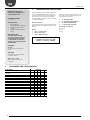
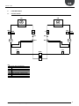
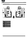
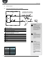
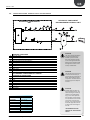
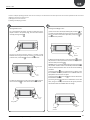
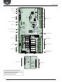
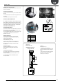
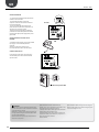
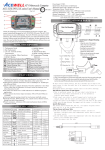
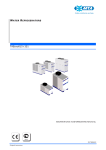
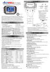
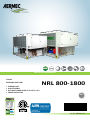
60Hz
INSTALLATION MANUAL
CHILLER
REVERSIBLE HEAT PUMP
• EXTERNAL UNIT
• HIGH EFFICENCY
• HOT WATER PRODUCING UP TO 131°F / 55°C
• POWER SUPPLY 60Hz
NRL 800-1800
EN
14_09. 4086991_01
Dear Customer,
Thank you for choosing an AERMEC product. This product is the result of many years of experience
and in-depth engineering research, and it is built using top quality materials and advanced technologies.
Moreover, the CE mark guarantees that our appliances fully comply with the requirements of the
European Machinery Directive in terms of safety. We constantly monitor the quality level of our
products, and as a result AERMEC products are synonymous with Safety, Quality, and Reliability.
Product data may be subject to modifications deemed necessary for improving the product without
the obligation to give prior notice.
Thank you again.
AERMEC S.p.A
AERMEC S.p.A. reserves the right at any moment to make any modifications considered necessary to improve our products and is not obliged to
add these modifications to machines that have already been fabricated, delivered or are under construction.
KEY:
2.
COMPONENTS AND CONFIGURATIONS............................... 4
1.
DESCRIPTION AND CHOCE OF UNIT..................................... 4
3.
COOLING CIRQUIT................................................................. 5
3.1.
NRL ONLY COOLING ............................................................. 5
3.2.
COOLING CIRQUIT NRL HEAT PUMP.................................... 6
4.
OPERATION LIMIT.................................................................. 7
4.1.
COOLING MODE ¹................................................................... 7
4.2.
HEATING MODE ¹.................................................................... 7
4.3.
PROJECT DATA........................................................................ 7
5.
SELECTION AND PLACE OF INSTALLATION.......................... 8
6.POSITIONING......................................................................... 8
6.1.
MINIMUM TECHNICAL (MM)................................................ 8
7.DIMENSIONS.......................................................................... 9
7.1.
NRL 800 - 900 - 1000 HA / NRL 800 900 1000 A .................. 9
7.2.
NRL 1250 - 1400 - 1500 - 1650 - 1800 HA / NRL 1250 - 1400 - 1500 - 1650 - 1800A / NRL 140 P1......................................... 9
8.
ANTIVIBRATION POSITIONING........................................... 10
8.1.
NRL 800 - 900 - 1000 HA ...................................................... 10
8.2.
NRL 800 - 900 - 1000 A ......................................................... 10
8.3.
NRL 1250 - 1400 - 1500 - 1650 - 1800 HA / NRL 1250 - 1400 - 1500 - 1650 - 1800A ............................................................ 11
8.4.
NRL 1400 P1.......................................................................... 11
9.
HYDRAULIC CONNECTION.................................................. 12
9.1.
NRL 800 - 900 HA ................................................................. 12
9.2.
NRL 800 - 900 A .................................................................... 12
9.4.
1000 HA ................................................................................ 13
9.3.
1000 A .................................................................................. 13
9.6.
NRL 1250 - 1400 - 1500 - 1650 - 1800 HA / NRL 1250 - 1400 - 1500 - 1650 - 1800A ............................................................ 14
9.5.
NRL 1400 HA P1.................................................................... 14
10.
DISTRIBUTION OF PERCENTAGE WEIGHTS ON .................... SUPPORTINGPOINTS........................................................... 15
11.
HYDRAULIC CIRCUIT............................................................ 23
11.1. INTERNAL AND EXTERNAL HYDRAULIC CIRCUIT "00" ......... (STANDARD)......................................................................... 23
11.2. INTERNAL AND EXTERNAL HYDRAULIC CIRCUIT - ............... NRL PUMP VERSION............................................................ 24
11.3. INTERNAL AND EXTERNAL HYDRAULIC CIRCUIT - ............... NRL PUMP VERSION AND STORAGE TANK........................ 25
12.
ELECTRICAL WIRINGS.......................................................... 26
12.1. RECOMMENDED SECTION OF ELECTRIC CABLES.............. 26
13.
ELECTRONIC CONTROL(PCO5)............................................ 27
14.
USER INTERFACE (PGD1)..................................................... 29
15.
START-UP PROCEDURE........................................................ 30
16.
MENU STRUCTURE AND NAVIGATION............................... 31
17.
USER OPERATING PROCEDURES......................................... 32
19.
ELECTRONIC CONTROL(GR3).............................................. 33
18.
ELECTRONIC CONTROL(GR3).............................................. 33
GB
NRL 800 - 1800
1.
Standards and Directives
respected on designing and
constructing the unit:
DESCRIPTION AND CHOCE OF UNIT
Chillers and heat pumps for outdoor condensed
in the air with R410A Series NRL have been designed and manufactured to satisfy heating and
cooling needs and the production of domestic
hot water (DHW) in medium to small commercial
or residential buildings.
PROTECTION RATING
1. IP 24
ACOUSTIC PART:
1. ISO DIS 9614/2
(INTENSIMETRIC METHOD))
2. SOUND POWER (EN ISO
9614-2)
3. SOUND PRESSURE (EN ISO
3744)
Maximum reliability
The presence of several scroll compressors allows
NRL chillers various partialisations of the cooling
capacity.
Models:
1. NRL "°" standard chiller
2. NRL "H" heat pump *
3. NRL "C" motocondensing
REFRIGERANT GAS:
This unit contains fluoride
gases with greenhouse effect
covered by the Kyoto Protocol. Maintenance and disposal must only be performed by
qualified staff.
The versions can be in different set-ups at the
same time in order to satisfy a wide range of
plant engineering solutions:
1.
2.
3.
4.
"A" HIGH EFFICIENCY
"E" SILENCED HIGH EFFICIENCY
"D" WITH DESUPERHEATER
"T" WITH TOTAL RECOVERY
Configurations not allowed:
YD / YT / YH
HT / HC
TC / DC
* Possibility of production of D.H.W.
(DCPX_UL | VMF-ACS | AER485).
STANDARD:
UL 1995
Heating and cooling equipment.
ANSI/NFPA
Standard 70 National Electrical code (N.E.C.).
CSA C.22.1.- C.22.2
Safety Standard Electrical
Installation.
2.
COMPONENTS AND CONFIGURATIONS
COMPONENTS
COOLING CIRCUIT
THERMOSTATIC VALVE X - Y (CONFIGURATION
OPTION)
EXCHANGER PLATE (EVAPORATOR)
EXCHANGER PLATE (TOTAL RECOVERY)
EXCHANGER PLATE (DESUPERHEATER)
AIR SIDE EXCHANGE
COMPRESSOR
DEHYDRATOR FILTER
HIGH PRESSURE SWITCH
HIGH PRESSURE TRANSDUCER
LOW PRESSURE TRANSDUCER
LIQUID INDICATOR
LIQUID TANK
ONE-WAY VALVES
LIQUID SEPARATOR
CYCLE REVERSE VALVE
4
VERSIONS
C
D
°
H
T
yes
yes
no
no
no
yes
no
no
yes
yes
yes
yes
yes
yes
yes
no
no
no
no
yes
no
no
yes
yes
yes
yes
yes
yes
yes
yes
yes
yes
yes
no
no
no
yes
yes
yes
yes
yes
yes
yes
no
no
no
no
yes
no
yes
yes
yes
yes
yes
yes
yes
yes
no
no
no
no
yes
yes
no
yes
yes
yes
yes
yes
yes
yes
yes
yes
yes
yes
Aermec cod. INRLLSIY 13_01. 4086991_00
GB
NRL 800 - 1800
3.
COOLING CIRQUIT
3.1.
NRL ONLY COOLING
CN
HPT
HPS
CP
LPT
CN
F
F
IDL
IDL
TEV
TEV
BHE
HPT
HPS
CP
LPT
KEY
KEY:
BHE
PLATE HEAT
EXCHANGER
BHE:
SCAMBIATORE
A PIASTRE
CN: BATTERIA
ALETTATA
CN AIR SIDE
EXSCHANGE
CP: COMPRESSORE
CP COMPRESSOR
F: FILTRO
DEIDRATATORE
F FILTER DRIER
HPS: PRESSOSTATO
DI ALTA PRESSIONE
HPT:HPS
TRASDUTTORE
ALTA PRESSIONE
HIGH PRESSURE
SWITCH
IDL: INDICATORE DI LIQUIDO
HIGH PRESSURE
TRANSDUCERS
LPT:HPT
TRASDUTTORE
BASSA PRESSIONE
IDL LIQUID INDICATOR
LPT LOW PRESSURE TRANSDUCER
Aermec cod. INRLLSIY 13_01. 4086991_00
5
GB
NRL 800 - 1800
3.2.
COOLING CIRQUIT NRL HEAT PUMP
CN
CV
CN
CV
CV
CV
AL
AL
VIC
VIC
F
F
HPT
IDL
HPS
CP
TEV
CV
LPT
CV
HPT
HPS
IDL
CP
LS
LS
BHE
TEV
LPT
CV
CV
KEY
KEY:
AL
BHE
CN
CP
CV
F
HPS
HPT
IDL
LPT
LS
VIC
6
AL: ACCUMULO DEL LIQUIDO
BHE: SCAMBIATORE A PIASTRE
CN: BATTERIA ALETTATA
CP: COMPRESSORE
CV: VALVOLA DI NON RITORNO
F: FILTRO DEIDRATATORE
HPS: PRESSOSTATO DI ALTA PRESSIONE
HPT: TRASDUTTORE ALTA PRESSIONE
IDL: INDICATORE DI LIQUIDO
LPT: TRASDUTTORE BASSA PRESSIONE
LS: SEPARATORE DI LIQUIDO
VIC: VALVOLA INVERSIONE CICLO
FLUID STORAGE TANK
PLATE HEAT EXCHANGER
AIR SIDE EXCHANGE
COMPRESSOR
ONE-WAY VALVES
FILTER DRIER
HIGH PRESSURE SWITCH
HIGH PRESSURE TRANSDUCERS
LIQUID INDICATOR
LOW PRESSURE TRANSDUCERS
LIQUID SEPARATOR
REVERSE CYCLE VALVE
Aermec cod. INRLLSIY 13_01. 4086991_00
GB
NRL 800 - 1800
4.
SELECTION AND PLACE OF
INSTALLATION
The unit must be installed by a qualified and suitably trained technician, in compliance with the
national legislation in force in the country of destination (Ministerial Decree 329/2004).
AERMEC will not assume any responsibility for damage due to failure to follow these instructions.
Before beginning installation consent with
client and pay attention to the following
recommendations:
− The support surface must be capable of
supporting the unit weight.
− The safety differences between the
unit and other appliances or structures
must be scrupulously respected so that
the inlet and outlet air from the fans is
free to circulate.
− The unit must be installed by an
enabled technician in compliance with
the national legislation in force in the
country of destination, respecting the
minimum technical spaces in order to
allow maintenance.
5.
Before beginning any operation, READ THESE INSTRUCTIONS CAREFULLY AND CARRY OUT THE SAFETY CHECKS TO REDUCE ALL RISK OF DANGER TO A MINIMUM. All the staff involved must have
thorough knowledge of the operations and any dangers that may arise at the moment in which
the installation operations are carried out.
−
out by qualified and adequately equipped
personnel. To handle the machine: see
figure
− attach the lifting belts to the relevant
eye-bolts (as indicated in figure).
ATTENTION: ALWAYS USE THE RELEVANT
EYE-BOLTS
− To ensure that the structure of the unit is
not damaged, place protection between
the lifting belt and the unit. It is strictly
prohibited to stand below the unit.
− Remember that whilst operational the
chiller can cause vibrations; therefore
anti-vibration mounts (AVX accessories)
are recommended, fixed in the holes
POSITIONING
The machine is delivered from the factory
wrapped in estincoil.
Before handling the unit, verify the lifting
capacity of the machines used.
After removal of packaging, movement of
apparatus must be carried
5.1.
−on the base according to the assembly
layout.
− It is mandatory to foresee to the necessary technical space in order to allow
ROUTINE AND EXTRAORDINARY MAINTENANCE interventions
− Fix the unit checking that it is level. Make
sure that the hydraulic and electric part
can be easily reached.
MINIMUM TECHNICAL (mm)
3000mm / 118.11in
HEIGHT
800 mm
31 in
800 mm
31 in
800 mm
31 in
1100 mm
43 in
ATTENTION:
ALWAYS USE
THE RELEVANT
EYE-BOLTS
Aermec cod. INRLLSIY 13_01. 4086991_00
7
GB
NRL 800 - 1800
6.
DIMENSIONS
6.1.
NRL 800 - 900 - 1000 HA / NRL 800 900 1000 A
2450 mm
96 in
4250 mm
167 in
2200 mm
87 in
6.2.
2450 mm
96 in
3400 mm
134 in
2200 mm
87 in
NRL 1250 - 1400 - 1500 - 1650 - 1800 HA / NRL 1250 - 1400 - 1500 - 1650 - 1800A / NRL 140 P1
2450 mm
96 in
5750 mm
226 in
2200 mm
87 in
8
Aermec cod. INRLLSIY 13_01. 4086991_00
GB
NRL 800 - 1800
ANTIVIBRATION POSITIONING
7.1.
NRL 800 - 900 - 1000 HA
1825 mm
72 in
1825 mm
72 in
100 mm
4 in
2100 mm 83 in
100 mm
4 in
100 mm
4 in
2000 mm 79 in
100 mm
4 in
7.
NRL 800 - 900 - 1000 A
100 mm
4 in
100 mm
4 in
2100 mm 83 in
2800 mm
110 in
100 mm
4 in
2000 mm 79 in
100 mm
4 in
7.2.
Aermec cod. INRLLSIY 13_01. 4086991_00
9
GB
NRL 800 - 1800
NRL 1250 - 1400 - 1500 - 1650 - 1800 HA / NRL 1250 - 1400 - 1500 - 1650 - 1800A
400 mm
16 in
1915mm
75 in
720 mm
28 in
1915mm
75 in
400 mm
16 in
50 mm
2 in
2100 mm
83 in
50 mm
2 in
7.3.
NRL 1400 P1
400 mm
16 in
1915mm
75 in
720 mm
28 in
1915mm
75 in
400 mm
16 in
10
2452
50 mm
2 in
2100 mm
83 in
50 mm
2 in
7.4.
Aermec cod. INRLLSIY 13_01. 4086991_00
GB
NRL 800 - 1800
8.
HYDRAULIC CONNECTION
8.1.
NRL 800 - 900 HA
3” IN
OUT
8.2.
3”
NRL 800 - 900 A
IN 3”
OUT 3”
Aermec cod. INRLLSIY 13_01. 4086991_00
11
GB
NRL 800 - 1800
8.4.
1000 HA
4” IN
OUT
8.3.
4”
1000 A
IN 4”
OUT 4”
12
Aermec cod. INRLLSIY 13_01. 4086991_00
GB
NRL 800 - 1800
8.6.
NRL 1250 - 1400 - 1500 - 1650 - 1800 HA / NRL 1250 - 1400 - 1500 - 1650 - 1800A
IN 4”
4” OUT
8.5.
NRL 1400 HA P1
IN 4”
OUT 4”
Aermec cod. INRLLSIY 13_01. 4086991_00
13
GB
NRL 800 - 1800
9.
DISTRIBUTION OF PERCENTAGE WEIGHTS ON SUPPORTINGPOINTS
Gy
1
3
2
4
5
7
6
8
G
Gx
TOP VIEW
VERSION COOLING ONLY
NRL
800
NRL
900
NRL
1000
14
A
A
A
Hydronic kit
MODEL
Version
EMPTY
WEIGHT
Lbs
XG mm
XG in
00
4134
1296
01
4861
1289
02
4971
03
4883
04
RUNNING
CENTRE OF GRAVITY
TOTAL
WEIGHT
YG mm
YG in
Lbs
51,02
954
37,55
4167
50,75
1066
41,98
6504
1288
50,72
1081
42,55
6614
1289
50,75
1068
42,07
6526
5016
1288
50,71
1085
42,72
P1
4475
1292
50,88
1012
P2
4586
1291
50,84
1029
P3
4497
1292
50,88
P4
4586
1291
50,85
00
4475
1344
01
5203
1330
02
5313
03
KIT AVX
CENTRE OF GRAVITY
WATER
XG mm
XG in
YG mm
YG in
33
1298
1642
1280
51,09
955
37,61
AVX 704
50,41
1223
48,17
AVX 705
1642
1642
1280
50,39
1232
48,49
AVX 705
1280
50,41
1225
48,22
6658
AVX 705
1642
1280
50,39
1234
48,59
AVX 705
39,82
40,50
4696
220
1292
50,88
1040
40,94
AVX 706
4806
220
1291
50,84
1056
41,56
1014
AVX 706
39,93
4718
220
1292
50,87
1042
41,04
AVX 706
1027
40,45
4806
220
1291
50,84
1055
41,52
AVX 706
52,90
927
36,51
4519
44
1345
52,96
929
36,59
AVX 710
52,38
1036
40,78
6856
1653
1313
51,68
1192
46,94
AVX 711
1329
52,31
1050
41,35
6967
1653
1312
51,64
1201
47,27
AVX 711
5269
1330
52,35
1043
41,08
6923
1653
1312
51,66
1197
47,12
AVX 711
04
5445
1327
52,24
1064
41,91
7099
1653
1311
51,60
1209
47,60
AVX 711
P1
4817
1337
52,63
983
38,69
5049
231
1335
52,56
1011
39,79
AVX 706
P2
4927
1335
52,56
999
39,35
5159
231
1333
52,49
1026
40,39
AVX 706
P3
4883
1336
52,59
991
39,03
5115
231
1334
52,52
1019
40,11
AVX 706
P4
5016
1334
52,51
1010
39,76
5247
231
1332
52,44
1036
40,77
AVX 706
00
4850
1330
52,34
933
36,75
4916
66
1332
52,42
936
36,85
AVX 716
01
5600
1319
51,93
1034
40,69
7275
1676
1305
51,39
1182
46,54
AVX 711
02
5710
1318
51,88
1047
41,22
7385
1676
1304
51,36
1190
46,86
AVX 711
03
5644
1318
51,91
1041
40,97
7319
1676
1305
51,37
1186
46,71
AVX 711
04
5820
1316
51,82
1060
41,74
7496
1676
1304
51,32
1198
47,18
AVX 711
P1
5214
1324
52,14
984
38,75
5467
254
1324
52,11
1011
39,79
AVX 712
P2
5324
1323
52,07
1000
39,36
5578
254
1322
52,05
1025
40,35
AVX 712
P3
5258
1323
52,10
992
39,07
5512
254
1323
52,08
1018
40,08
AVX 712
P4
5390
1322
52,03
1009
39,74
5644
254
1321
52,01
1034
40,70
AVX 712
Aermec cod. INRLLSIY 13_01. 4086991_00
GB
NRL 800 - 1800
VERSION COOLING ONLY
DEL
NRL
1250
NRL
1400
NRL
1500
NRL
1650
NRL
1800
A
A
A
A
A
Hydronic kit
MO-
Version
EMPTY
WEIGHT
RUNNING
CENTRE OF GRAVITY
TOTAL
WEIGHT
lbs
XG mm
XG in
YG mm
YG in
KIT AVX
CENTRE OF GRAVITY
WATER
Lbs
XG mm
XG in
YG mm
YG in
00
7275
2168
85,34
940
37,01
7341
66
2162
85,10
942
37,08
AVX 7012
01
8003
2203
86,71
1010
39,74
9678
1676
2256
88,80
1125
44,30
AVX 7013
02
8113
2207
86,91
1019
40,13
9789
1676
2259
88,93
1132
44,57
AVX 7013
03
8069
2205
86,81
1015
39,94
9744
1676
2257
88,87
1129
44,44
AVX 7013
04
8245
2212
87,10
1029
40,52
9921
1676
2262
89,07
1139
44,84
AVX 7013
P1
7617
2185
86,02
975
38,37
7871
254
2188
86,14
993
39,11
AVX 7014
P2
7727
2190
86,23
985
38,79
7981
254
2193
86,34
1003
39,50
AVX 7014
P3
7683
2188
86,13
980
38,59
7937
254
2191
86,24
999
39,31
AVX 7014
P4
7815
2194
86,37
992
39,06
8069
254
2196
86,47
1010
39,76
AVX 7014
00
7496
2503
98,53
929
36,57
7562
66
2504
98,59
930
36,62
AVX 7009
01
8223
2507
98,69
998
39,27
9899
1676
2515
99,02
1112
43,78
AVX 7010
02
8333
2507
98,72
1007
39,65
10009
1676
2515
99,03
1119
44,05
AVX 7010
03
8289
2507
98,71
1003
39,47
9965
1676
2515
99,03
1116
43,92
AVX 7010
04
8466
2508
98,74
1017
40,04
10141
1676
2516
99,05
1126
44,32
AVX 7010
P1
7837
2505
98,61
963
37,91
8091
254
2507
98,71
981
38,62
AVX 7009
P2
7948
2505
98,64
974
38,33
8201
254
2508
98,74
991
39,01
AVX 7009
P3
7904
2505
98,62
968
38,13
8157
254
2508
98,72
986
38,82
AVX 7009
P4
8036
2506
98,65
980
38,60
8289
254
2508
98,75
997
39,26
AVX 7009
00
7760
2477
97,54
914
35,97
7826
66
2479
97,61
915
36,02
AVX 7009
01
8488
2484
97,78
981
38,64
10163
1676
2496
98,25
1096
43,14
AVX 7010
02
8598
2485
97,82
991
39,02
10274
1676
2496
98,27
1103
43,41
AVX 7010
03
8554
2484
97,80
986
38,84
10229
1676
2496
98,26
1099
43,28
AVX 7010
04
8708
2485
97,85
1001
39,40
10384
1676
2497
98,30
1109
43,68
AVX 7010
P1
8102
2481
97,66
947
37,29
8356
254
2484
97,79
965
37,99
AVX 7009
P2
8212
2482
97,70
958
37,70
8466
254
2485
97,82
975
38,38
AVX 7009
P3
8168
2481
97,68
953
37,51
8422
254
2484
97,81
970
38,20
AVX 7009
P4
8278
2482
97,72
964
37,97
8532
254
2485
97,85
981
38,63
AVX 7009
00
8113
2522
99,28
894
35,21
8179
66
2523
99,34
896
35,27
AVX 734
01
8863
2524
99,37
961
37,83
10538
1676
2529
99,57
1075
42,31
AVX 735
02
8973
2524
99,39
970
38,21
10648
1676
2529
99,58
1081
42,57
AVX 735
03
8907
2524
99,38
966
38,03
10582
1676
2529
99,58
1078
42,44
AVX 735
04
9083
2525
99,40
980
38,58
10759
1676
2530
99,59
1088
42,84
AVX 735
P1
8477
2523
99,33
927
36,51
8730
254
2525
99,40
945
37,20
AVX 736
P2
8587
2523
99,34
938
36,91
8841
254
2525
99,41
955
37,59
AVX 736
P3
8521
2523
99,33
933
36,72
8774
254
2525
99,41
950
37,40
AVX 736
P4
8653
2524
99,35
944
37,17
8907
254
2525
99,42
961
37,83
AVX 736
00
8422
2493
98,14
875
34,46
8488
66
2494
98,20
877
34,52
AVX 798
01
9149
2497
98,32
941
37,06
10825
1676
2506
98,67
1055
41,53
AVX 799
02
9259
2498
98,34
951
37,43
10935
1676
2507
98,69
1062
41,79
AVX 799
03
9215
2498
98,33
946
37,25
10891
1676
2507
98,68
1058
41,67
AVX 799
04
9392
2499
98,37
960
37,80
11067
1676
2507
98,71
1068
42,06
AVX 799
P1
8763
2495
98,23
908
35,74
9017
254
2498
98,33
925
36,44
AVX 800
P2
8874
2496
98,25
918
36,14
9127
254
2498
98,35
935
36,82
AVX 800
P3
8830
2495
98,24
913
35,95
9083
254
2498
98,34
931
36,64
AVX 800
P4
8962
2496
98,27
925
36,40
9215
254
2499
98,37
941
37,06
AVX 800
Aermec cod. INRLLSIY 13_01. 4086991_00
15
GB
NRL 800 - 1800
Gy
1
3
2
4
5
7
6
8
G
Gx
TOP VIEW
NRL
800
NRL
900
NRL
1000
16
HA
HA
HA
Hydronic kit
MODEL
Version
VERSION HEAT PUMP
EMPTY
WEIGHT
RUNNING
CENTRE OF GRAVITY
TOTAL
WEIGHT
Lbs
XG mm
XG in
YG mm
YG in
Lbs
00
5732
2027
80
946
37
5776
01
6460
2001
79
1043
41
02
6570
1998
79
1056
42
03
6482
2000
79
1045
04
6614
1996
79
1060
P1
6074
2014
79
P2
6184
2010
79
P3
6096
2013
79
P4
6184
2010
79
KIT AVX
CENTRE OF GRAVITY
WATER
XG mm
XG in
YG mm
YG in
44
2031
80
947
37
AVX 7003
8113
1653
1965
77
1193
47
AVX 7004
8223
1653
1962
77
1202
47
AVX 7004
41
8135
1653
1964
77
1195
47
AVX 7004
42
8267
1653
1962
77
1204
47
AVX 7004
994
39
6305
231
2012
79
1019
40
AVX 7005
1009
40
6415
231
2008
79
1033
41
AVX 7005
997
39
6327
231
2011
79
1022
40
AVX 7005
1008
40
6415
231
2008
79
1032
41
AVX 7005
00
5952
1780
70
929
37
5997
44
1781
70
931
37
AVX 7006
01
6680
1782
70
1024
40
8333
1653
1786
70
1175
46
AVX 7008
02
6812
1782
70
1038
41
8466
1653
1787
70
1183
47
AVX 7008
03
6746
1782
70
1031
41
8400
1653
1787
70
1179
46
AVX 7008
04
6923
1783
70
1051
41
8576
1653
1787
70
1192
47
AVX 7008
P1
6294
1781
70
977
38
6526
231
1783
70
1002
39
AVX 7007
P2
6426
1781
70
992
39
6658
231
1783
70
1016
40
AVX 7007
P3
6360
1781
70
985
39
6592
231
1783
70
1009
40
AVX 7007
P4
6493
1782
70
1001
39
6724
231
1783
70
1024
40
AVX 7007
00
6129
1751
69
913
36
6195
66
1752
69
915
36
AVX 7006
01
6878
1756
69
1007
40
8554
1676
1765
69
1157
46
AVX 7007
02
6989
1757
69
1020
40
8664
1676
1766
70
1166
46
AVX 7007
03
6923
1756
69
1014
40
8598
1676
1765
70
1162
46
AVX 7007
04
7099
1757
69
1033
41
8774
1676
1766
70
1175
46
AVX 7007
P1
6493
1753
69
960
38
6746
254
1756
69
985
39
AVX 7008
P2
6603
1754
69
975
38
6856
254
1757
69
999
39
AVX 7008
P3
6537
1754
69
968
38
6790
254
1756
69
992
39
AVX 7008
P4
6669
1754
69
984
39
6923
254
1757
69
1007
40
AVX 7008
Aermec cod. INRLLSIY 13_01. 4086991_00
GB
NRL 800 - 1800
NRL
1250
NRL
1400
NRL
1500
NRL
1650
NRL
1800
HA
HA
HA
HA
HA
Hydronic kit
MODEL
Version
VERSION HEAT PUMP
EMPTY
WEIGHT
RUNNING
CENTRE OF GRAVITY
TOTAL
WEIGHT
Lbs
XG mm
XG in
YG mm
YG in
Lbs
00
8113
2531
100
927
37
8179
01
8841
2537
100
1000
39
02
8951
2538
100
1010
40
03
8907
2537
100
1005
KIT AVX
CENTRE OF GRAVITY
WATER
XG mm
XG in
YG mm
YG in
66
2532
100
929
37
AVX 7009
10516
1676
2547
100
1123
44
AVX 7010
10626
1676
2548
100
1130
45
AVX 7010
40
10582
1676
2548
100
1127
44
AVX 7010
04
9083
2538
100
1020
40
10759
1676
2549
100
1138
45
AVX 7010
P1
8455
2534
100
963
38
8708
254
2536
100
983
39
AVX 7011
P2
8565
2535
100
974
38
8818
254
2537
100
993
39
AVX 7011
P3
8521
2534
100
969
38
8774
254
2537
100
988
39
AVX 7011
P4
8653
2535
100
982
39
8907
254
2538
100
1000
39
AVX 7011
00
8179
2517
99
922
36
8245
66
2519
99
923
36
AVX 7009
01
8907
2524
99
994
39
10582
1676
2537
100
1117
44
AVX 7010
02
9039
2525
99
1004
40
10714
1676
2537
100
1124
44
AVX 7010
03
8973
2525
99
999
39
10648
1676
2537
100
1121
44
AVX 7010
04
9149
2526
99
1015
40
10825
1676
2538
100
1132
45
AVX 7010
P1
8521
2521
99
957
38
8774
254
2524
99
976
38
AVX 7011
P2
8653
2522
99
969
38
8907
254
2525
99
987
39
AVX 7011
P3
8587
2521
99
963
38
8841
254
2524
99
982
39
AVX 7011
P4
8719
2522
99
976
38
8973
254
2525
99
994
39
AVX 7011
00
8223
2494
98
919
36
8311
88
2496
98
920
36
AVX 7009
01
8951
2503
99
991
39
10648
1698
2519
99
1114
44
AVX 7010
02
9061
2504
99
1001
39
10759
1698
2520
99
1121
44
AVX 7010
03
8995
2503
99
996
39
10692
1698
2519
99
1118
44
AVX 7010
04
9171
2505
99
1012
40
10869
1698
2520
99
1129
44
AVX 7010
P1
8565
2498
98
955
38
8841
276
2502
99
973
38
AVX 7011
P2
8675
2500
98
966
38
8951
276
2503
99
984
39
AVX 7011
P3
8609
2499
98
960
38
8885
276
2503
99
979
39
AVX 7011
P4
8741
2500
98
973
38
9017
276
2504
99
991
39
AVX 7011
00
8554
2534
100
901
35
8642
88
2536
100
903
36
AVX 734
01
9281
2540
100
972
38
10979
1698
2550
100
1094
43
AVX 735
02
9392
2540
100
982
39
11089
1698
2550
100
1102
43
AVX 735
03
9348
2540
100
977
38
11045
1698
2550
100
1098
43
AVX 735
04
9502
2541
100
992
39
11199
1698
2551
100
1109
44
AVX 735
P1
8896
2537
100
936
37
9171
276
2540
100
955
38
AVX 736
P2
9006
2538
100
947
37
9281
276
2540
100
966
38
AVX 736
P3
8962
2537
100
942
37
9237
276
2540
100
961
38
AVX 736
P4
9072
2538
100
954
38
9348
276
2541
100
972
38
AVX 736
00
8818
2508
99
881
35
8907
88
2509
99
882
35
AVX 737
01
9546
2515
99
951
37
11244
1698
2528
100
1074
42
AVX 738
02
9656
2516
99
961
38
11354
1698
2529
100
1081
43
AVX 738
03
9590
2515
99
957
38
11288
1698
2529
100
1077
42
AVX 738
04
9766
2517
99
972
38
11464
1698
2530
100
1088
43
AVX 738
P1
9160
2511
99
916
36
9436
276
2514
99
934
37
AVX 736
P2
9270
2512
99
927
36
9546
276
2515
99
945
37
AVX 736
P3
9204
2512
99
921
36
9480
276
2515
99
940
37
AVX 736
P4
9337
2513
99
934
37
9612
276
2516
99
951
37
AVX 736
Aermec cod. INRLLSIY 13_01. 4086991_00
17
GB
NRL 800 - 1800
VERSION COOLING ONLY
PERCENTAGE OF WEIGHT DISTRIBUTION SUPPORTS (%)
MODEL
NRL
800
NRL
900
NRL
1000
NRL
1250
NRL
1400
18
A
A
A
A
A
1
2
3
4
5
6
7
8
%
%
%
%
%
%
%
%
00
11,7%
15,2%
26,4%
34,3%
5,4%
7,0%
-
-
01
11,8%
9,4%
40,7%
32,5%
3,1%
2,5%
-
-
02
11,8%
9,3%
41,2%
32,4%
3,0%
2,3%
-
-
03
11,8%
9,4%
40,8%
32,5%
3,1%
2,4%
-
-
04
11,8%
9,2%
41,4%
32,4%
3,0%
2,3%
-
-
P1
11,9%
13,2%
30,6%
34,1%
4,8%
5,4%
-
-
P2
11,9%
12,9%
31,4%
34,0%
4,7%
5,1%
-
-
P3
11,9%
13,2%
30,7%
34,1%
4,8%
5,4%
-
-
P4
11,9%
12,9%
31,3%
34,0%
4,7%
5,1%
-
-
00
10,3%
14,1%
26,3%
35,9%
5,6%
7,7%
-
-
01
10,8%
9,1%
39,9%
33,7%
3,5%
3,0%
-
-
02
10,8%
9,0%
40,3%
33,6%
3,4%
2,9%
-
-
03
10,8%
9,0%
40,1%
33,6%
3,5%
2,9%
-
-
04
10,8%
8,8%
40,8%
33,5%
3,3%
2,7%
-
-
P1
10,6%
12,5%
30,2%
35,5%
5,2%
6,1%
-
-
P2
10,6%
12,2%
31,0%
35,4%
5,1%
5,8%
-
-
P3
10,6%
12,3%
30,6%
35,5%
5,1%
5,9%
-
-
P4
10,6%
12,0%
31,4%
35,3%
5,0%
5,6%
-
-
00
10,2%
13,8%
27,3%
36,8%
5,1%
6,9%
-
-
01
10,7%
9,2%
39,9%
34,3%
3,2%
2,8%
-
-
02
10,7%
9,1%
40,3%
34,2%
3,1%
2,6%
-
-
03
10,7%
9,1%
40,1%
34,3%
3,2%
2,7%
-
-
04
10,7%
8,9%
40,8%
34,1%
3,0%
2,5%
-
-
P1
10,4%
12,3%
30,8%
36,3%
4,7%
5,5%
-
-
P2
10,5%
12,0%
31,5%
36,2%
4,6%
5,2%
-
-
P3
10,5%
12,1%
31,2%
36,2%
4,6%
5,3%
-
-
P4
10,5%
11,8%
32,0%
36,1%
4,5%
5,1%
-
-
00
11,9%
16,0%
22,5%
30,1%
2,0%
2,7%
6,3%
8,5%
01
10,5%
10,0%
28,8%
27,5%
6,4%
6,1%
5,5%
5,2%
02
10,4%
9,8%
29,0%
27,4%
6,6%
6,2%
5,4%
5,1%
03
10,4%
9,9%
28,9%
27,4%
6,5%
6,2%
5,5%
5,2%
04
10,3%
9,6%
29,3%
27,3%
6,8%
6,3%
5,4%
5,0%
P1
11,7%
14,2%
24,2%
29,4%
3,1%
3,8%
6,2%
7,5%
P2
11,6%
13,8%
24,5%
29,3%
3,3%
4,0%
6,1%
7,3%
P3
11,6%
14,0%
24,4%
29,3%
3,2%
3,9%
6,1%
7,4%
P4
11,5%
13,6%
24,8%
29,2%
3,5%
4,1%
6,1%
7,2%
00
7,7%
10,6%
16,0%
21,9%
13,4%
18,3%
5,1%
6,9%
01
6,7%
6,6%
22,7%
22,2%
16,7%
16,3%
4,4%
4,3%
02
6,7%
6,5%
23,0%
22,2%
16,8%
16,2%
4,4%
4,2%
03
6,7%
6,5%
22,9%
22,2%
16,7%
16,3%
4,4%
4,3%
04
6,6%
6,3%
23,3%
22,2%
16,9%
16,2%
4,3%
4,1%
P1
7,6%
9,4%
17,8%
22,1%
14,3%
17,8%
4,9%
6,2%
P2
7,5%
9,2%
18,1%
22,1%
14,5%
17,7%
4,9%
6,0%
P3
7,5%
9,3%
18,0%
22,1%
14,4%
17,7%
4,9%
6,1%
P4
7,5%
9,0%
18,4%
22,1%
14,6%
17,6%
4,9%
5,9%
Aermec cod. INRLLSIY 13_01. 4086991_00
GB
NRL 800 - 1800
VERSION COOLING ONLY
PERCENTAGE OF WEIGHT DISTRIBUTION SUPPORTS (%)
MODEL
NRL 1500
NRL 1650
NRL 1800
A
A
A
1
2
3
4
5
6
7
8
%
%
%
%
%
%
%
%
00
7,9%
11,1%
15,7%
22,0%
13,2%
18,5%
4,8%
6,8%
01
7,0%
7,0%
22,3%
22,4%
16,4%
16,5%
4,2%
4,2%
02
6,9%
6,9%
22,5%
22,4%
16,5%
16,4%
4,2%
4,2%
03
6,9%
7,0%
22,4%
22,4%
16,4%
16,5%
4,2%
4,2%
04
6,9%
6,7%
22,8%
22,4%
16,6%
16,3%
4,1%
4,1%
P1
7,7%
9,9%
17,4%
22,3%
14,0%
18,0%
4,7%
6,0%
P2
7,7%
9,7%
17,7%
22,3%
14,2%
17,9%
4,7%
5,9%
P3
7,7%
9,8%
17,6%
22,3%
14,1%
17,9%
4,7%
5,9%
P4
7,7%
9,5%
18,0%
22,3%
14,3%
17,8%
4,7%
5,8%
00
7,4%
10,8%
14,5%
21,2%
14,0%
20,4%
4,8%
7,0%
01
6,6%
6,9%
20,9%
21,9%
17,1%
17,9%
4,2%
4,4%
02
6,6%
6,8%
21,2%
21,9%
17,2%
17,8%
4,2%
4,4%
03
6,6%
6,8%
21,1%
21,9%
17,1%
17,8%
4,2%
4,4%
04
6,5%
6,7%
21,5%
21,9%
17,3%
17,7%
4,2%
4,3%
P1
7,3%
9,6%
16,2%
21,5%
14,8%
19,7%
4,7%
6,2%
P2
7,2%
9,4%
16,5%
21,6%
15,0%
19,6%
4,7%
6,1%
P3
7,2%
9,5%
16,4%
21,5%
14,9%
19,6%
4,7%
6,1%
P4
7,2%
9,3%
16,7%
21,6%
15,1%
19,5%
4,6%
6,0%
00
7,3%
11,0%
15,1%
22,8%
12,9%
19,5%
4,5%
6,9%
01
6,6%
7,1%
21,3%
23,1%
16,0%
17,4%
4,1%
4,4%
02
6,5%
7,0%
21,5%
23,1%
16,2%
17,3%
4,0%
4,3%
03
6,6%
7,1%
21,4%
23,1%
16,1%
17,4%
4,0%
4,4%
04
6,5%
6,9%
21,8%
23,1%
16,3%
17,2%
4,0%
4,2%
P1
7,2%
9,9%
16,7%
23,0%
13,8%
19,0%
4,5%
6,1%
P2
7,1%
9,7%
17,0%
23,0%
13,9%
18,9%
4,4%
6,0%
P3
7,2%
9,8%
16,8%
23,0%
13,9%
18,9%
4,4%
6,1%
P4
7,1%
9,5%
17,2%
23,0%
14,1%
18,8%
4,4%
5,9%
Aermec cod. INRLLSIY 13_01. 4086991_00
19
GB
NRL 800 - 1800
VERSION HEAT PUMP
PERCENTAGE OF WEIGHT DISTRIBUTION SUPPORTS (%)
MODEL
NRL 800
NRL 900
NRL 1000
NRL 1250
NRL 1400
20
HA
HA
HA
HA
HA
1
2
3
4
5
6
7
8
%
%
%
%
%
%
%
%
00
7,7%
10,2%
25,1%
33,2%
10,2%
13,5%
-
-
01
7,5%
6,3%
38,1%
32,1%
8,7%
7,3%
-
-
02
7,5%
6,2%
38,5%
32,0%
8,6%
7,1%
-
-
03
7,5%
6,3%
38,1%
32,1%
8,7%
7,3%
-
-
04
7,5%
6,2%
38,7%
32,0%
8,6%
7,1%
-
-
P1
7,8%
9,0%
28,6%
33,2%
10,0%
11,5%
-
-
P2
7,7%
8,7%
29,3%
33,1%
9,9%
11,2%
-
-
P3
7,8%
8,9%
28,7%
33,2%
9,9%
11,5%
-
-
P4
7,7%
8,8%
29,3%
33,1%
9,9%
11,2%
-
-
00
8,7%
11,9%
28,2%
38,4%
5,4%
7,4%
-
-
01
8,5%
7,4%
40,5%
35,3%
4,4%
3,9%
-
-
02
8,5%
7,3%
40,9%
35,2%
4,4%
3,8%
-
-
03
8,5%
7,3%
40,7%
35,2%
4,4%
3,8%
-
-
04
8,4%
7,1%
41,4%
35,0%
4,3%
3,7%
-
-
P1
8,8%
10,5%
31,6%
37,7%
5,2%
6,2%
-
-
P2
8,8%
10,2%
32,2%
37,6%
5,2%
6,0%
-
-
P3
8,8%
10,3%
31,9%
37,7%
5,2%
6,1%
-
-
P4
8,8%
10,1%
32,7%
37,5%
5,1%
5,9%
-
-
00
9,0%
12,6%
27,6%
38,7%
5,0%
7,1%
-
-
01
8,8%
7,9%
39,6%
35,7%
4,2%
3,8%
-
-
02
8,8%
7,8%
40,1%
35,6%
4,1%
3,7%
-
-
03
8,8%
7,8%
39,9%
35,6%
4,2%
3,7%
-
-
04
8,7%
7,6%
40,6%
35,4%
4,1%
3,6%
-
-
P1
9,0%
11,1%
30,9%
38,1%
4,9%
6,0%
-
-
P2
9,0%
10,9%
31,5%
37,9%
4,8%
5,8%
-
-
P3
9,0%
11,0%
31,2%
38,0%
4,9%
5,9%
-
-
P4
9,0%
10,7%
31,9%
37,8%
4,8%
5,7%
-
-
00
7,1%
9,7%
16,3%
22,3%
14,0%
19,1%
4,9%
6,7%
01
6,3%
6,1%
22,3%
21,4%
18,0%
17,3%
4,3%
4,2%
02
6,3%
6,0%
22,6%
21,4%
18,2%
17,2%
4,3%
4,1%
03
6,3%
6,0%
22,5%
21,4%
18,1%
17,2%
4,3%
4,1%
04
6,3%
5,8%
22,8%
21,3%
18,3%
17,1%
4,3%
4,0%
P1
7,0%
8,6%
17,9%
22,1%
15,0%
18,6%
4,8%
5,9%
P2
6,9%
8,4%
18,2%
22,1%
15,3%
18,5%
4,8%
5,8%
P3
6,9%
8,5%
18,0%
22,1%
15,1%
18,6%
4,8%
5,9%
P4
6,9%
8,3%
18,4%
22,1%
15,4%
18,5%
4,8%
5,7%
00
7,0%
9,7%
16,4%
22,6%
14,0%
19,4%
4,6%
6,3%
01
6,3%
6,1%
22,4%
21,7%
18,1%
17,5%
4,1%
3,9%
02
6,2%
6,0%
22,6%
21,6%
18,2%
17,4%
4,0%
3,9%
03
6,3%
6,0%
22,5%
21,7%
18,1%
17,5%
4,0%
3,9%
04
6,2%
5,9%
22,9%
21,6%
18,4%
17,4%
4,0%
3,8%
P1
6,9%
8,6%
17,9%
22,5%
15,1%
18,9%
4,5%
5,6%
P2
6,8%
8,4%
18,2%
22,4%
15,3%
18,8%
4,5%
5,5%
P3
6,9%
8,5%
18,1%
22,4%
15,2%
18,9%
4,5%
5,6%
P4
6,8%
8,3%
18,4%
22,4%
15,4%
18,7%
4,4%
5,4%
Aermec cod. INRLLSIY 13_01. 4086991_00
GB
NRL 800 - 1800
VERSION HEAT PUMP
PERCENTAGE OF WEIGHT DISTRIBUTION SUPPORTS (%)
MODEL
NRL 1500
NRL 1650
NRL 1800
HA
HA
HA
1
2
3
4
5
6
7
8
%
%
%
%
%
%
%
%
00
7,3%
10,1%
16,3%
22,7%
13,7%
19,1%
4,5%
6,3%
01
6,6%
6,4%
22,3%
21,7%
17,8%
17,3%
4,0%
3,9%
02
6,5%
6,3%
22,5%
21,7%
17,9%
17,2%
4,0%
3,8%
03
6,6%
6,3%
22,4%
21,7%
17,8%
17,3%
4,0%
3,9%
04
6,5%
6,2%
22,8%
21,6%
18,1%
17,2%
3,9%
3,7%
P1
7,2%
9,0%
17,9%
22,5%
14,8%
18,6%
4,4%
5,6%
P2
7,1%
8,8%
18,2%
22,5%
15,0%
18,5%
4,4%
5,4%
P3
7,2%
8,9%
18,0%
22,5%
14,9%
18,6%
4,4%
5,5%
P4
7,1%
8,7%
18,4%
22,5%
15,1%
18,5%
4,4%
5,3%
00
6,9%
10,0%
15,1%
21,7%
14,4%
20,7%
4,6%
6,6%
01
6,3%
6,4%
21,0%
21,2%
18,3%
18,5%
4,1%
4,1%
02
6,3%
6,3%
21,2%
21,2%
18,5%
18,4%
4,1%
4,1%
03
6,3%
6,3%
21,1%
21,2%
18,4%
18,5%
4,1%
4,1%
04
6,2%
6,1%
21,5%
21,1%
18,6%
18,3%
4,0%
4,0%
P1
6,8%
8,9%
16,6%
21,7%
15,4%
20,1%
4,5%
5,9%
P2
6,8%
8,7%
17,0%
21,7%
15,7%
20,0%
4,5%
5,7%
P3
6,8%
8,8%
16,8%
21,7%
15,6%
20,1%
4,5%
5,8%
P4
6,8%
8,6%
17,2%
21,7%
15,8%
19,9%
4,5%
5,6%
00
6,8%
10,1%
15,7%
23,4%
13,4%
19,9%
4,3%
6,4%
01
6,2%
6,6%
21,4%
22,4%
17,3%
18,1%
3,9%
4,1%
02
6,2%
6,4%
21,6%
22,4%
17,4%
18,0%
3,9%
4,0%
03
6,2%
6,5%
21,5%
22,4%
17,3%
18,1%
3,9%
4,1%
04
6,2%
6,3%
21,9%
22,3%
17,6%
17,9%
3,9%
3,9%
P1
6,7%
9,1%
17,1%
23,2%
14,4%
19,5%
4,3%
5,8%
P2
6,7%
8,9%
17,4%
23,2%
14,6%
19,4%
4,2%
5,6%
P3
6,7%
9,0%
17,3%
23,2%
14,5%
19,4%
4,2%
5,7%
P4
6,7%
8,8%
17,6%
23,1%
14,7%
19,3%
4,2%
5,5%
Aermec cod. INRLLSIY 13_01. 4086991_00
21
GB
NRL 800 - 1800
IONE “00”
10.
HYDRAULIC CIRCUIT
10.1.
INTERNAL AND EXTERNAL HYDRAULIC CIRCUIT "00" (STANDARD)
HYDRAULIC COMPONENTS
NRL
4
2
EXTERNAL UNIT HYDRAULIC
RECOMMENDED COMPONENT
7
14
11
8
14
6
10
1
6
13
4
3
15
7
9
12
STANDARD COMPONENT
1 Exchanger plate (SYSTEM SIDE)
2 Water filter
FORNITO
DI(supplied)
SERIE:
3
Flow
switch
(supplied)
1. scambiatore
4 Water temperature probes (IN/OUT)
2. filtro acqua
3. flussostato
RECOMMENDED COMPONENTS NOT SUPPLIED
(CHARGED
TO THE INSTALLER)
4. sonde
temperatura
acqua (IN-OUT)
6 Air Vent
5.7 rubinetto
scarico
Anti-vibrationdi
couplings
6.8 valvola
di sfiato
Pump
9
10
11
12
13
14
15
Storage tank
Expansion tank
Safety valve
Ball stop Tank
Charging unit
Ball Stop
Manometer
PH
Electric
conductivity
Chloride ions
Sulphuric acid ions
Total iron
Alkalinity M
Total hardness
Sulphur ions
ammonia ions
Silicone ions
22
6-8
less than 200 mV/cm
(77°F / 25°C)
less than 50 ppm
less than 50 ppm
less than 0.3 ppm
less than 50 ppm
less than 50 ppm
none
none
less than 30 ppm
NON FORNITO / CONSIGLIATO:
6. valvola di sfiato
7. giunti antivibranti
8. pompa
9. accumulo
10. vaso d’espansione
11. valvola di sicurezza (bar..?)
12. scarico accumulo
13. gruppo di caricamento
14. valvola d’intercettazione
15. manometro
ATTENTION
The choice and the installation
of components external to
the NRL up to the installer,
who must operate according
to the rules of good technical
design and in compliance with
the regulations in force in the
country of destination.
ATTENTION
The hydraulic pipes connecting
to the machine must be properly sized to the actual flow of
water required by the system
in operation. The water flow to
the exchanger must always be
constant.
ATTENTION
Carefully wash the plant, before connecting the unit. This
allows cleaning to remove any
residue such as weld spatter,
slag, rust or other impurities
from the pipes. These substances may otherwise accumulate
in and cause a machine malfunction. The connecting pipes
should be supported so as not
to weigh, with their weight on
the unit.
THE DRAWINGS ARE ONLY
EXAMPLES OF THE HYDRAULIC
CIRCUIT.
Aermec cod. INRLLSIY 13_01. 4086991_00
GB
NRL 800 - 1800
IONE “POMPE”
10.2.
INTERNAL AND EXTERNAL HYDRAULIC CIRCUIT - NRL PUMP VERSION
HYDRAULIC COMPONENT
RECOMMENDED EXTERNAL UNIT
HYDRAULIC COMPONENT
NRL
4
11
8
2
14
10
6
6
14
7
11
6
1
10
13
4
3
15
7
9
5
12
1.
2.
3.
4.
5.
6.
8.
10.
11.
14.
STANDARD COMPONENT
Exchanger plate
Water filter (fitted)
FORNITO
DI SERIE:
Flow
switch (fitted)
1.
scambiatore
Water temperature probes (IN-OUT)
2.
acqua
Ballfiltro
stop drain
3.
flussostato
Air Vent
Pump
4.
sonde temperatura acqua (IN-OUT)
Expansion tank
5.
rubinetto di scarico
Safety valve
6.
di sfiato
Ballvalvola
Stop
8. pompa
RECOMMENDED
COMPONENTS NOT SUPPLIED
10.
vaso d’espansione
(CHARGED TO THE INSTALLER)
vavola di sicurezza (bar...?)
6. 11.
Air Vent
valvola couplings
d’intercettazione
7. 14.
Anti-vibration
9.
10.
12.
13.
14.
15.
Tank
Expansion tank
Ball Stop Tank
Charging unit
Ball Stop
Manometer
PH
Electric
conductivity
Chloride ions
Sulphuric acid ions
Total iron
Alkalinity M
Total hardness
Sulphur ions
ammonia ions
Silicone ions
6-8
less than 200 mV/cm
(77°F / 25°C)
less than 50 ppm
less than 50 ppm
less than 0.3 ppm
less than 50 ppm
less than 50 ppm
none
none
less than 30 ppm
Aermec cod. INRLLSIY 13_01. 4086991_00
ATTENTION
The choice and the installation
of components external to
NON FORNITO / CONSIGLIATO:
the NRL up to the installer,
who must operate according
6. valvola di sfiato
to the rules of good technical
7. giunti antivibranti design and in compliance with
the regulations in force in the
9. accumulo
country of destination.
10. vaso d’espansione
11. valvola di sicurezza (bar..?)
12. scarico accumulo
ATTENTION
13. gruppo di caricamento
The hydraulic pipes connecting
14. valvola d’intercettazione
to the machine must be properly sized to the actual flow of
15. manometro
water required by the system
in operation. The water flow to
the exchanger must always be
constant.
ATTENTION
Carefully wash the plant, before connecting the unit. This
allows cleaning to remove any
residue such as weld spatter,
slag, rust or other impurities
from the pipes. These substances may otherwise accumulate
in and cause a machine malfunction. The connecting pipes
should be supported so as not
to weigh, with their weight on
the unit.
THE DRAWINGS ARE ONLY
EXAMPLES OF THE HYDRAULIC
CIRCUIT.
23
GB
NRL 800 - 1800
NE “POMPE+ACCUMULO”
10.3.
INTERNAL AND EXTERNAL HYDRAULIC CIRCUIT - NRL PUMP VERSION AND STORAGE TANK
HYDRAULIC COMPONENT
NRL
11
4
8
2
6
14
9
HYDRAULIC COMPONENT
RECOMMENDED EXTERNAL UNIT
10
7
14
6
1
4
10
3
12
13
15
7
5
STANDARD COMPONENT
1. Exchanger plate
2. Water filter (fitted)
3. Flow switch (fitted)
4. Water temperature
FORNITO
DI SERIE: probes (IN-OUT)
5. Ball stop drain
1. scambiatore
6. Air Vent
2. filtro
acqua
8. Pump
9. Tank
3. flussostato
Expansion
tank
4.10.
sonde
temperatura
acqua (IN-OUT)
11. Safety valve
5.12.
rubinetto
di scarico
Ball stop Tank
6.14.
valvola
di
Ball Stop sfiato
8. pompa
RECOMMENDED COMPONENTS NOT SUPPLIED
9. accumulo
(CHARGED TO THE INSTALLER)
10.6.vaso
d’espansione
Air Vent
7.
Anti-vibration
couplings (bar...?)
11. vavola di sicurezza
10. Expansion tank
12. scarico accumulo
13. Charging unit
14. Ball Stop
15. Manometer
PH
Electric
conductivity
Chloride ions
Sulphuric acid ions
Total iron
Alkalinity M
Total hardness
Sulphur ions
ammonia ions
Silicone ions
24
6-8
less than 200 mV/cm
(77°F / 25°C)
less than 50 ppm
less than 50 ppm
less than 0.3 ppm
less than 50 ppm
less than 50 ppm
none
none
less than 30 ppm
ATTENTION
The choice and the installation
of components external to
the NRL up to the installer,
who must operate according
to the rules of good technical
NON FORNITO / CONSIGLIATO:
design and in compliance with
6. valvola di sfiato
the regulations in force in the
country of destination.
7. giunti antivibranti
10. vaso d’espansione
13. gruppo di caricamento
14. val
ATTENTION
The hydraulic pipes connecting
to the machine must be properly sized to the actual flow of
water required by the system
in operation. The water flow to
the exchanger must always be
constant.
ATTENTION
Carefully wash the plant, before connecting the unit. This
allows cleaning to remove any
residue such as weld spatter,
slag, rust or other impurities
from the pipes. These substances may otherwise accumulate
in and cause a machine malfunction. The connecting pipes
should be supported so as not
to weigh, with their weight on
the unit.
THE DRAWINGS ARE ONLY
EXAMPLES OF THE HYDRAULIC
CIRCUIT.
Aermec cod. INRLLSIY 13_01. 4086991_00
GB
NRL 800 - 1800
11.
ELECTRICAL WIRINGS
The default NRL chillers are completely wired and
only need the connection to the power supply net,
downstream to a group switch, according to the to
the regulations in force in the country where the
machine is installed.
It is also suggested to check:
• the mains supply characteristics, to ensure it is
suitable for the levels indicated in the electrical
data table, also taking into consideration any other
equipment that may be operating at the same time.
• The unit is only powered after the last (hydraulic
and electric) installations.
• Follow the connections instructions of the phase
conductors, and earth.
• The power line will have a special protection
upstream against short circuits and earth losses that
sections the system according to other users.
• The voltage should be within a tolerance of ±
10% of the rated supply voltage of the machine (for
Three-phase units displacement max 3% between
the phases). If these parameters are not respected,
contact the energy supplier. For electrical wirings use
isolated double cables according to the standards in
force in the different countries.
• It is necessary to use a omnipolar thermomagnetic
switch, in compliance with the CEI-EN standards
(contact opening of at least 3 mm), with adequate
switch capability and differential protection based on
the followed electrical data table, installed as close
as possible to the machine.
• It is necessary to carry out an efficient earth
connection. The manufacturer can not be held responsible for any damage caused by the failure and
ineffective earthing of the machine.
• For units with Three-phase power check the correct connection of the phases.
WARNING
It is forbidden to use water pipes for the earthing of
the machine.
11.1. RECOMMENDED SECTION OF ELECTRIC
CABLES
The cable sections indicated in the table are advised
for a maximum length of 50 m.
For higher lengths or different types of cable installation, it will be the DESIGNERS responsibility to carefully measure the line main switch, the supply power
line and the earthing protection connection, and the
working connection cables:
• the length
• the type of cable
• Absorption of the unit and its physical position,
and room temperature.
WARNING:
Check that all power cables are
correctly secured to the terminals when switched
on for the first time and after 30 days of use. Afterwards, check the connection of the power cables
every six months.Slack terminals could cause the
cables and components to overheat.
ATTENTION
All electrical operations must
be carried out by qualified
personnel, in accordance with
the corresponding regulations, trained and informed
about the risks related to such
operations.
ATTENTION
The characteristics of electric
lines and related components must be established by
personnel authorised to design
electric installations, following
international regulations and
the national regulations of the
country in which the unit is installed, in compliance with the
legislative regulations in force
at the moment of installation.
ATTENTION
For installation requirements,
the wiring layout supplied with
the unit must be compulsory
referred to. The wiring layout
together with the manuals
must be kept in good conditions and readily accessible for
future operations on the unit.
ATTENTION
it is compulsory to check the
machine sealing before connecting the electrical wiring.
The machine should only be
powered once the hydraulic
and electric operations are
completed.
Aermec cod. INRLLSIY 13_01. 4086991_00
25
GB
NRL 800 - 1800
12.
ELECTRONIC CONTROL(PCO5)
ELECTRONIC CONTROL (pCO5)
START-UP
CIRCULATING PUMP
1.
2.
3.
4.
Turn the unit on (ON)
Start Pump
Controlwaterflowrate(20seconds):
Flow switch or pressure switch (if provided)
Whenever alarms do not occur, the compressor
starts.
ANTI-FREEZE ALARM
WATER FLOW ALARM
Reference parameters:
Ifthewaterflowrateisnotsufficient,thissafetystops
the compressors and the pump
Compressor
BLOCK - OFF
ON
3°C <
> 3°C
Temperature
Maxoperations
n° 2
Cod.Anti-freezealarm
See User Manual
Restart
Manual
Electical Heater
OFF
ON
Temperature
> 5°C
4°C <
OFF
ON
Circulating Pump
Temperature
> 5°C
4°C <
Only for pure water (not added with glycol)
Water
Pump
Waterflowrate
isnotsufficient
Cod. Alarm
Waterflowrate
issufficient
BLOCCO - OFF
ON
Flow Switch
or
Pressure Switch (if provided)
>20 seconds
Compressor not work
See User Manual
-
>20 seconds
Start Compressor
Versions with Total Recovery and Condensing
Units are equipped with GR3 electronics
(standard remote panel)
All the other versions have pCO5 electronics
(remote panel available as accessory)
26
Aermec cod. INRLLSIY 13_01. 4086991_00
GB
NRL 800 - 1800
AUXILIARY CONNECTIONS
(For Standard Version)
Remote Control
(PGD1)
Circulating Pump
J12 - N01 (CP01)
External Alarm
J15 - N08/C8/NC8
Circulating Pump
J22 - N018 (CP02)
External Circuit Breaker
J20 - IDC17 (0/1)
200
200 m
m
Cavo schermato
CavoAWG24
schermato
2AWG24
twisted pair
65 432 10
2 twisted pair
6 5 4 3 2 1 0
S90CONN
6 5 4 3 2 10
0,8 m
I/ O
KIT PGD1
(ACCESSORIO)
I/ O
set
set
prog.
max 50 m
telefonico
Cavocavo
telefonico
prog.
S90CONN*:
cavo di collegame nto
Cavo telefonico
• The address to enable
remote panel is 31
Formoreinformation,refertothewiringdiagramsintheselectionprogramorsitewww.aermec.com
Aermec cod. INRLLSIY 13_01. 4086991_00
27
GB
NRL 800 - 1800
User USER
Interface
(PGD1)
13.
INTERFACE
(PGD1)
The unit control panel allow the quick setting and
display of the unit’s operating parameters. The board
memorises all the default settings and any modifications. By installing the remote control panel PGD1 it is
possible to remotely replicate all the functions and the
settings available on the unit. After a power failure the
unit is capable of an automatic restart, retaining the
original settings.
The user interface consists of a graphic display with
six navigation keys; the display is arranged through a
menu hierarchy, activated by pressing the navigation
keys. The default display of these menus is the main
screen. The navigation between the various parameters is by using the arrow keys located to the right of
the display. These keys are also used for the modification of the selected parameter.
INTERFACE CONTROL KEYS
Control Keys
Key
Fucntion
ALARM key
Displays the list of active and historical alarms
(red LED on = active alarm)
Control Keys
MENU ACTIVATION key
• Pressing this key activates the navigation between menus
(orange
LED on = winter operating mode active)
EXIT MENU key
• Pressing this key returns to the previous menu
(+) key
NAVIGATION
•Pressingthiskeywhennavigatingbetweenmenu/parameterspassestothenext
menu/parameter
• Pressing this key when modifying a parameter increases the value of the selected parameter
28
NAVIGATION (enter) key
• Pressing this key when navigating between menus allows entry to the selected menu
• Pressing this key when navigating between parameters allows selection of the parameter
displayed to modify it
• Pressing the key when modifying a parameter confirms the modification of the parameter value
selected
NAVIGATION (-) key
•Pressingthiskeywhennavigatingbetweenmenu/parameterspassestothepreviousmenu/
parameter
• Pressing this key when modifying a parameter decreases the value of the selected parameter
Aermec cod. INRLLSIY 13_01. 4086991_00
GB
NRL 800 - 1800
Start-up
procedure
14.
START-UP
PROCEDURE
After having powered up the unit the control board will
carry out preliminary operations before being ready
for use. This initial procedure takes around 60 seconds
to complete. During the initial loading procedure two
screens are displayed: a start-up screen and a screen to
select the system language. These screens are detailed
in the table below.
WARNING: The system language can be set on the
screen displayed at the start-up or can be modified at
Display on the unit
Wait please
6s
Index
Display/Parameter
A
Remaining time for software loading: this value shows the remaining time to starting the software loaded on the unit, and passing the
to system language selection
B
System language: this parameter shows the current language set for
the system. To change the language follow the instructions shown on
the screen.
A
Installer
Language:
B
English
ENTER for change
ESC to confirm
Time show mask:
any time through the appropriate screen contained
in the Installer menu.
20
C
C
Remaining time to select the language: this value shows the
remaining time to modify the language. When the time elapses the
display goes to the main screen (Main screen - General monitoring).
WARNING: It is possible to modify the system language at any
time using the appropriate screen contained in the Installer menu.
(Menu password = 0000).
WARNING: It is possible to modify the system language at any time using the appropriate screen contained in the Installer menu. (Menu password = 0000).
Aermec cod. INRLLSIY 13_01. 4086991_00
29
GB
NRL 800 - 1800
15.
MENU STRUCTURE
AND
Menu structure
and navigati
on NAVIGATION
Boththefunctionstocontroltheunitandtheoperatinginformation
are displayed on the unit mounted control panel. All the functions
andinformationarearrangedinscreenswhichinturnaregrouped
into menus.
The operating menus are arranged as in the following drawing:
A
Duringthenormaloperationoftheunitthemainscreenisdisplayed,
fromwhichitispossibletoaccesstheselectionoftheotheroperating
menus.
Themenusaredisplayedthroughtherotationoftheiconsthatthey
represent. Once the desired icon is selected the chosen menu is entered,permitti
ngthedisplayormodificationoftheparametersthatit
ismadeupfrom.Theprocedurefornavigatingthemenus,orchangingparameters,isexplainedindetailinthechapter“Useroperating
procedures”.
Theadjacentdrawingshowstherelationbetweenthevariousmenus
andthenavigationkeysused.
B
I
C
H
D
WARNING: Improper selection of the parameters in the Installer
menu may cause malfunctions of the unit. It is recommended that
these parameters are only modified by personnel qualified in the
installation and configuration of the unit.
G
E
F
30
Index
Icon
Menu
Menu function
A
---
MAIN
The screens in this menu display the current conditions of the unit (unit status, setpoints,circuit data, etc.)
B
IN/OUT
This menu contains advanced information on the unit operation
C
ON/OFF
This menu permits the unit to be enabled or disabled, and provides information on the status
D
SYSTEM
This menu permits the selection of the operating modes, the water setpoints and the time-clock for the system
E
RECOVERY
If the unit includes heat recovery, this menu permits the setting of the parameters associated with the heat recovery
F
INSTALLER
This menu contains the settings useful for the installer (enabling digital inputs, BMS configuration, control, pumps, etc.)
WARNING: This menu is password protected. The password is: 0000
G
ASSISTANCE
This menu is only accessible to qualified personnel
H
FACTORY
This menu is only accessible to qualified personnel
I
CLOCK
This menu contains the clock settings for the system control (date, hour, calender)
Aermec cod. INRLLSIY 13_01. 4086991_00
GB
NRL 800 - 1800
16.UserUSER
OPERATING
PROCEDURES
operating
procedures
Tocheckormodifytheoperatingparametersoftheunititisnecessarytousetheinterfaceofthecontrolpanelontheunit.Thebasicoperationsthattheusermustbe
capable of, for the correct use of the unit, are:
(1) Moving from one menu to the next.
(2)Selectingandmodifyingaparameter.
2
1
Moving between menus
Selecting and modifying a menu
(a) To move between the menus, the order in which they are displayed is shown in the previous page, enter the menu selection
(a) Once in the menu selected, by following the procedure ( 1 ), it
is possible to move between the screens using the arrow keys: the
key ( ) to move to the previous parameter, and the key ( ) to
move to the next parameter.
mode by pressing the key (
).
previous parameter
(b) Once in the menu selection mode it is possible to move
between menus using the arrow keys: the key ( ) to move to the
previous menu, and the key ( ) to move to the next menu.
next
parameter
(c) When the desired parameter is seen press the key ( ) to enter
the parameter. To exit the parameter and return to the parameter
selection mode press the key ( ).
WARNING: Once a parameter is selected by pressing the key ( ),
the parameter selection mode is automatically accessed and in this
mode the desired parameter values can be set with the following
procedure:
(1) Pressing the key ( ) causes a flashing cursor to appear on the
first modifiable field of the parameter. If no modifiable fields are
displayed then the cursor will not appear.
(2) Pressing the key ( ) or the key ( ), the value of the field can
be increased or decreased.
(3) Pressing the key ( ) confirms the modification of the field
value, saving it in memory. On the basis of the type of parameter
selected the number of modifiable fields can change.
previous menu
next
menu
(c) When the desired menu is seen press the key ( )to enter the
menu. Press the key( ) to return to the menu selection mode.
entering a
menu
exiting a menu
entering a parameter
exiting a
parameter
Aermec cod. INRLLSIY 13_01. 4086991_00
31
GB
ELECTRONIC CONTROL (PCO5)
NRL 800 - 1800
17.
18.
ELECTRONIC CONTROL(GR3)
Digital inputs
M1
Not used
M2
Display
M24
M3
M23
1
ON
2
3
4 5
6
1
7 8
M22
Analogue inputs
1
ON
2
3
SW2
ON
SW1
DIP SWITCH
4
DCP analogue outputs
Not used
M21
M4
M20
M5
F US
E
24Vac power supply
Remote panel
M19
M6
M7
M18
24Vac power supply
M17
Clean contact
alarms summary
E
M8
FUS
Digital inputs
M9
M16
M10
1
ON
M15
2
220V digital outputs
4 5
SW3
3
DIP SWITCH
M11
M14
Digital inputs
M12
M13
ESP2
ESP2
220V power supply
digital outputs
ESP1
ESP1
M1
M3
Digital outputs
M2
M2
Digital outputs
M3
M1
Versions with Total Recovery and Condensing Units
are equipped with GR3 electronics (standard remote panel)
All the other versions have pCO5 electronics
(remote panel available as accessory)
32
Aermec cod. INRLLSIY 13_01. 4086991_00
GB
NRL 800 - 1800
CONNECTION TO THE POWER SUPPLY
Accertarsi che non ci sia presenza di tensione sulla linea elettrica a cui vi allaccerete.
TO ACCESS THE ELECTRIC BOX
Turn ¼ the screws of the electrical panel in counter-clockwise
direction
Turnthehandleofthedoor-blockdisconnectingswitchtoOFF
(seefigure).
In this way, the electrical panel can be accessed
ELECTRICAL POWER CONNECTION
Forfunctionalconnectionoftheunittakethesupply
power cable to the electrical panel inside the unit in
thepreviouspageandconnectittothedisconnecting
switch terminals observing the phase, and the earth.
L
AUXILIARY CONNECTIONS AT THE
USER/INSTALLER EXPENSE
Theterminalsindicatedinfutureexplanationsarepartofthe
GR 3 control boards. For installation requirements, refer to
the wiring diagram supplied with the unit.
The wiring diagram together with the manuals must be kept
ingoodconditionsandreadilyaccessibleforfuture
operationsontheunit.
AUXILIARY SWITCH (IAD)
To prepare the auxiliary switch, connect the device
to the clamp 4 of the control board M7 SC and to the
clamp 4 of the remote panel.
PUMP CONTACTOR (CP01 - CP02)
To prepare the pump contactor, connect the device
CP01 to the clamp 2 of the control board M16 SC and
the device CP02 to the clamp 4 and 6 of the control
board M1 SE2.
EXTERNAL ALARM (EA)
To prepare an external alarm device, connect the
device contact to the clamp 1 and 2 of the control
board M17.
R
SET
L
C1
R
R
C2
Fig. 1
Key fig.1
L1
Line 1
L2
Line 2
L3
Line 3
PE
Earth
CONNECTION
REMOTE PANEL - PR3
COMANDO A DISTANZA
REMOTE CONTROL
M7 SC
CONNECTION PR3 (STANDARD)
Connect the remote panel PR3 to the control board M7
SC (as shown below),
remember that the maximum allowed distance is 50 m.
6
5
4
3
2
1
THE PR3 CONNECTED MUST BE ENABLED, AS WELL.
See next procedure.
ENABLING
REMOTE PANEL - PR3
To enable the remote panel PR3:
-actontheL/Rkeyonthesmallpanelofthe
GR3onthemachine(asshowninthefigure
above)
-whentheLEDnexttotheletterR(Remote)
lightsup,themachinefunctionwillbe
enabled by the remote panel.
IAD
6 x 0,5 MAX 50m
7
6
5
4
3
2
1
0
ALARM
1
PR
Aermec cod. INRLLSIY 13_01. 4086991_00
33
GB
NRL 800 - 1800
SEASON CHANGEOVER
- For each seasonal change check that the operation
conditions return to the limit.
- Check that the absorption current of the
compressor is less than the maximum indicated in
the technical data table.
- Check in the models with three-phase supply
power that the noise level of the compressor is not
abnormal, in this case invert a phase.
- Make sure that the voltage value are within the
prefixed limits and that the displacements between
the three phases (three-phase supply power) do not
get above 3%.
Led On
SET
L
Fig. 4
C2
SEASON CHANGE OF THE PANEL ON THE
MACHINE
R
R
C1
Fig. 3
To activate the season change, just press the indicated
key in (fig. 5). To ensure that the operation is
successful,
machine must be active as remote or local.
For further information refer to the USE manual.
SEASON CHANGE OF PR3
Just act directly on the switch. The machine turns
off automatically and it restarts with the selected
operation mode.
SET
L
C1
R
R
C2
Fig. 5
Remote panel PR3
ATTENTION
1)Commissioning must be performed with standard settings.
Only when the inspection has been completed can the functioning Set Point values by changed.
Before start-up, power the unit for at least 12-24 hours, positioning the protection magnet circuit breaker switch and the
door lock isolating switch at ON.
Make sure that the control panel is off in order to allow the
compressor oil sump to heat.
34
2) We recommend to envision a machine book (not
supplied, but the user’s responsibility), which allows to keep
track of the interventions performed on the unit.
In this way it will be easy to suitably organise the interventions
making research and the prevention of any
machine breakdowns easier. Use the date to record date, type
of intervention made (routine maintenance, inspection or repairs), description of the intervention,
measures actuated.
3)It is forbidden to LOAD the cooling circuit with a refrigerant
different to that indicated. Using a different refrigerant gas can
cause serious damage to the unit.
Aermec cod. INRLLSIY 13_01. 4086991_00
cartariciclata
reciclata
carta
recycledpaper
paper
recycled
papier
papierrecyclé
recyclé
recycled
recycledPapier
papier
37040 Bevilacqua (VR) - Italy
Via Roma, 996 - Tel. (+39) 0442 633111
Telefax (+39) 0442 93730 – (+39) 0442 93566
www.aermec.com
The technical data in the following documentation are not binding. Aermec
reserves the right to make all the modifications considered necessary for
improving the product at any time.