1
FUJITSU SEMICONDUCTOR
CONTROLLER MANUAL
CM81-00204-1E
FR FAMILY
F²MC FAMILY
32/16/8-BIT MICROCONTROLLER
SOFTUNE C COMPILER MANUAL
FR FAMILY
F²MC FAMILY
32/16/8-BIT MICROCONTROLLER
SOFTUNE C COMPILER MANUAL
FUJITSU LIMITED
PREFACE
■ Objective of This Manual and Target Readers
This manual describes the F2MC-16 family C compiler (hereinafter referred to as the compiler)
usage procedures and libraries.
This manual is prepared for persons who use the above-mentioned compiler and create and
development application programs in C language.
This manual is to be read by persons who have a basic knowledge of each MCU (Micro
Controller Unit).
The compiler described in this manual conforms to the American National Standard for
Information Systems Programming Language C, X3.159-1989, which is abbreviated
"ANSI standard" in this manual.
■ Notes on Trademarks
Microsoft and Windows are registered trademarks of Microsoft Corp.
UNIX is a registered trademark that X/Open Co., Ltd. has licensed in the United States and
other countries.
Other trademarks or registered trademarks are the property of their respective owners. The
or mark is not used within this manual.
■ Composition of Manual
This manual consists of the following chapters.
Chapter 1
GENERAL
This chapter outlines the C compiler.
Chapter 2
SETUP OF SYSTEM EMVIRONMENT BEFORE USING C COMPILER
This chapter describes the C compiler operating environment variables.
Chapter 3
OPERATION
This chapter describes the command function specifications.
Chapter 4
OBJECT PROGRAM STRUCTURE
This chapter describes the information necessary for program execution.
Chapter 5
EXTENDED LANGUAGE SPECIFICATIONS
This chapter describes the extended language specifications supported by the compiler
and the limitations on compiler translation.
Chapter 6
EXECUTION ENVIRONMENT
This chapter describes the user program execution procedure to be performed in an
environment where no operating system exists.
Chapter 7
LIBRARY OVERVIEW
This chapter outlines the C libraries by describing the organization of files provided by the
libraries and the relationship to the system into which the libraries are incorporated.
i
Chapter 8
LIBRARY INCORPORATION
This chapter describes the processes and functions to be prepared for library use.
Chapter 9
COMPILER-DEPENDENT SPECIFICATIONS
This chapter describes the specifications that vary with the compiler.
Chapter 10
SIMULATOR DEBUGGER LOW-LEVEL FUNCTION LIBRARY
This chapter describes how to use the simulator debugger low-level function library.
APPENDIX
The Appendix gives a list of types, macros, and functions provided by the library and the
operations specific to the libraries(A,B). Notes when FFMC-16LX CPU is used are
described(C).
■ Syntax Books
For C language syntax and standard library functions, refer to commercially available ANSI
standard compliant reference books.
■ Reference Books
• The C Programming Language
(Brian W. Kernighan & Dennis M. Ritchie)
• Japanese edition entitled Programming Language C UNIX Type Programming Method and
Procedure
(Translated by Haruhisa Ishida; Kyoritsu Shuppan)
• American National Standard for Information Systems æ Programming Language C, X3.1591989
(Western Electric Company, Incorporated)
• UNIX System User's Manual System V
(Western Electric Company, Incorporated)
• UNIX System V Programmer Reference Manual
(AT&T Bell Laboratories)
• User Reference Manual UTS/5 Release 0.1
(Western Electric Company, Incorporated and Amdahl Corporation)
• UTS Command Reference Manual UTS/5 Release 0.1
(Western Electric Company, Incorporated and Amdahl Corporation)
• Japanese Industrial Standards Programming Language C
(Japan Standards Association)
ii
1. The contents of this document are subject to change without notice. Customers are advised to consult
with FUJITSU sales representatives beforeordering.
2. The information and circuit diagrems in this document presented as examples of semiconductor device
applications, and are not intended to be incorporated in devices for actual use. Also FUJITSU is unable
to assume responsibility for infringement of any patent rights or other rights of third parties arising from
the use of this information or circuit diagrams.
3. The contents of this document may not be reproduced or copied without the permission of FUJITSU
LIMITED.
4. FUJITSU semiconductor devices are intended for use in standard applications (computers, office
automation and other office equipments, industrial, communications, and measurement equipments,
personal or household devices, etc.).
CAUTION:
Customers considering the use of our products in special applications where failure or abnormal
operation may directly affect human lives or cause physical injury or property damage, or where
extremely high levels of reliability are demanded (such as aerospace systems, atomic energy controls,
sea floor repeaters, vehicle operating controls, medical devices for life support, etc.) are requested to
consult with FUJITSU sales representatives before such use. The company will not be responsible for
damages arising from such use without prior approval.
5. Any semiconductor devices have inherently a certain rate of failure. You must protect against injury,
damage or loss from such failures by incorporating safety design measures into your facility and
equipment such as redundancy, fire protection, and prevention of over-current levels and other
abnormal operating conditions.
6. If any products described in this document represent goods or technologies subject to certain
restrictions on export under the Foreign Exchange and Foreign Trade Control Law of Japan, the prior
authorization by japanese government should be required for export of those products from Japan.
© 1999 FUJITSU LIMITED Printed in Japan
iii
USING THIS MANUAL
■ Manual Configuration
Reading two facing pages enables you to understand the contents without turning the page.
The summary below the title will help you understand the outline of each chapter and section.
■ How To Find Your Information
You can find information via the table of contents or the index at the end of the manual.
■ Conventions
The following notational conventions are used in this manual.
[item]
:
{item 1|item 2} :
item ...
:
The items enclosed within square brackets are omissible.
Either item 1 or item 2 must be specified. This rule also takes effect
when there are three or more items.
The specifying of this item can be repeated any number of times.
Examples set forth in this manual are based on the UNIX OS convention.
■ Product Naming
Products in this manual are named as follows:
• Windows95 means Microsoft Windows95 operating system.
• WindowsNT means Microsoft WindowsNT Server network operating system Versions 3.51
and 4.0 and Microsoft WindowsNT Workstation operating system Versions 3.51 and 4.0.
• Windows means Microsoft Windows operating system Version 6.2.
iv
■ Layout of Facing Pages
v
vi
CONTENTS
CHAPTER 1
1.1
1.2
1.3
C COMPILER FUNCTIONS ....................................................................................................................2
BASIC PROCESS OF COMMANDS .......................................................................................................3
C COMPILER BASIC FUNCTIONS.........................................................................................................6
CHAPTER 2
2.1
2.2
2.3
2.4
2.5
2.6
GENERAL .......................................................................................................1
SETUP OF SYSTEM EMVIRONMENT BEFORE USING C COMPILER .......9
FETOOL ................................................................................................................................................10
LIB911/LIB896 .......................................................................................................................................11
OPT907/OPT911/OPT896.....................................................................................................................12
INC907/INC911/INC896 ........................................................................................................................13
TMP .......................................................................................................................................................14
FELANG ................................................................................................................................................15
CHAPTER 3
OPERATION .................................................................................................17
3.1 COMMAND LINE...................................................................................................................................18
3.2 COMMAND OPERANDS.......................................................................................................................19
3.3 FILE NAMES AND DIRECTORY NAMES.............................................................................................20
3.4 COMMAND OPTIONS...........................................................................................................................21
3.4.1
List of Command Options .................................................................................................................23
3.4.2
List of Command Cancel Options.....................................................................................................26
3.5 DETAILS OF OPTIONS.........................................................................................................................28
3.5.1
Translation Control Related Options ................................................................................................29
3.5.2
Preprocessor Related Options .........................................................................................................32
3.5.3
Data Output Related Options ...........................................................................................................36
3.5.4
Language Specification Related Options .........................................................................................43
3.5.5
Optimization Related Options...........................................................................................................50
3.5.6
Output Object Related Options.........................................................................................................58
3.5.7
Debug Information Related Options .................................................................................................64
3.5.8
Command Related Options ..............................................................................................................65
3.5.9
Linkage Related Options ..................................................................................................................66
3.5.10 Option File Related Options .............................................................................................................68
3.6 OPTION FILES ......................................................................................................................................69
3.7 MESSAGES GENERATED IN TRANSLATION PROCESS..................................................................71
CHAPTER 4
4.1
4.2
4.3
4.4
4.5
4.6
4.7
4.8
4.9
4.10
OBJECT PROGRAM STRUCTURE .............................................................73
fcc907s COMMAND SECTION STRUCTURE ......................................................................................74
fcc911s COMMAND SECTION STRUCTURE ......................................................................................77
fcc896s COMMAND SECTION STRUCTURE ......................................................................................79
MEMORY MODELS ..............................................................................................................................81
GENERATION RULES FOR NAMES USED BY COMPILER ...............................................................83
fcc907s COMMAND BOUNDARY ALIGNMENT ...................................................................................84
fcc911s COMMAND BOUNDARY ALIGNMENT ...................................................................................85
fcc896s COMMAND BOUNDARY ALIGNMENT ...................................................................................86
fcc907s COMMAND BIT FIELD.............................................................................................................87
fcc911s COMMAND BIT FIELD.............................................................................................................89
vii
4.11 fcc896s COMMAND BIT FIELD............................................................................................................ 91
4.12 fcc907s COMMAND STRUCTURE/UNION.......................................................................................... 93
4.13 fcc911s COMMAND STRUCTURE/UNION.......................................................................................... 95
4.14 fcc896s COMMAND STRUCTURE/UNION.......................................................................................... 97
4.15 fcc907s COMMAND FUNCITON CALL INTERFACE........................................................................... 98
4.15.1 fcc907s Command Stack Frame...................................................................................................... 99
4.15.2 fcc907s Command Argument ........................................................................................................ 101
4.15.3 fcc907s Command Argument Extension Format ........................................................................... 102
4.15.4 fcc907s Command Calling Procedure ........................................................................................... 103
4.15.5 fcc907s Command Register .......................................................................................................... 104
4.15.6 fcc907s Command Return Value ................................................................................................... 105
4.16 fcc911s COMMAND FUNCTION CALL INTERFACE......................................................................... 106
4.16.1 fcc911s Command Stack Frame.................................................................................................... 107
4.16.2 fcc911s Command Argument ........................................................................................................ 109
4.16.3 fcc911s Command Argument Extension Format ........................................................................... 111
4.16.4 fcc911s Command Calling Procedure ........................................................................................... 112
4.16.5 fcc911s Command Register .......................................................................................................... 113
4.16.6 fcc911s Command Return Value ................................................................................................... 114
4.17 fcc896s COMMAND FUNCITON CALL INTERFACE......................................................................... 115
4.17.1 fcc896s Command Stack Frame.................................................................................................... 116
4.17.2 fcc896s Command Argument ........................................................................................................ 118
4.17.3 fcc896s Command Argument Extension Format ........................................................................... 119
4.17.4 fcc896s Command Calling Procedure ........................................................................................... 120
4.17.5 fcc896s Command Register .......................................................................................................... 121
4.17.6 fcc896s Command Return Value ................................................................................................... 122
4.18 fcc907s COMMAND INTERRUPT FUNCITON CALL INTERFACE ................................................... 123
4.18.1 fcc907s Command Interrupt Stack Frame ..................................................................................... 124
4.18.2 fcc907s Command Interrupt Function Calling Procedure .............................................................. 125
4.19 fcc911s COMMAND INTERRUPT FUNCITON CALL INTERFACE ................................................... 126
4.19.1 fcc911s Command Interrupt Stack Frame ..................................................................................... 127
4.19.2 fcc911s Command Interrupt Function Calling Procedure .............................................................. 128
4.20 fcc896s COMMAND INTERRUPT FUNCITON CALL INTERFACE ................................................... 129
4.20.1 fcc896s Command Interrupt Stack Frame ..................................................................................... 130
4.20.2 fcc896s Command Interrupt Function Calling Procedure .............................................................. 131
CHAPTER 5
5.1
5.2
5.3
5.4
5.5
5.6
5.7
5.8
5.9
5.10
5.11
5.12
5.13
viii
EXTENDED LANGUAGE SPECIFICATIONS ............................................133
ASSEMBLER DESCRIPITON FUNCTIONS ...................................................................................... 134
INTERRUPT CONTROL FUNCITONS............................................................................................... 141
I/O AREA ACCESS FUNCTION ......................................................................................................... 146
direct AREA ACCESS FUNCTION ..................................................................................................... 149
16-BIT/24-BIT ADDRESSING ACCESS FUNCTION ......................................................................... 151
IN-LINE EXPANSION SPECIFYING FUNCTION............................................................................... 153
SECTION NAME CHANGE FUNCTION............................................................................................. 154
REGISTER BANK NUMBER SETUP FUNCTION.............................................................................. 156
INTERRUPT LEVEL SETUP FUNCTION........................................................................................... 157
SYSTEM STACK USE SPECIFYING FUNCTION ............................................................................. 159
STACK BANK AUTOMATIC DISTINCTION FUNCTION ................................................................... 160
NO-REGISTER-SAVE INTERRUPT FUNC. FUNCTION ................................................................... 161
BUILT-IN FUNCTION ......................................................................................................................... 162
5.14 PREDEFINED MACROS.....................................................................................................................167
5.15 LIMITATIONS ON COMPILER TRANSLATION..................................................................................169
CHAPTER 6
6.1
6.2
EXECUTION PROCESS OVERVIEW.................................................................................................172
STARTUP ROUTINE CREATION .......................................................................................................174
CHAPTER 7
7.1
7.2
COMPILER-DEPENDENT SPECIFICATIONS ...........................................199
COMPILER-DEPENDENT LANGUAGE SPECIFICAITON DIFFERENTIALS ....................................200
FLOATING-POINT DATA FORMAT AND EXPRESSIBLE VALUE RANGE.......................................202
CHAPTER 0
0.1
0.2
0.3
0.4
0.5
0.6
LIBRARY INCORPORATION .....................................................................183
LIBRARY INCORPORATION OVERVIEW..........................................................................................184
INITIALIZATION/TERMINATION PROCESS REQUIRED FOR LIBRARY USE.................................185
LOW-LEVEL FUNCTION TYPES........................................................................................................186
STANDARD LIBRARY FUNCTIONS AND REQUIRED PROCESS/LOW-LEVEL FUNCTIONS........187
LOW-LEVEL FUNCTION SPECIFICAITONS......................................................................................188
open Function.................................................................................................................................189
close Function ................................................................................................................................190
read Function..................................................................................................................................191
write Function .................................................................................................................................192
lseek Function ................................................................................................................................193
isatty Function ................................................................................................................................194
sbrk Function ..................................................................................................................................195
_exit Function .................................................................................................................................196
_abort Function...............................................................................................................................197
CHAPTER 9
9.1
9.2
LIBRARY OVERVIEW ................................................................................177
FILE ORGANIZATION.........................................................................................................................178
RELATIONSHIP TO LIBRARY INCORPORATING SYSTEM.............................................................181
CHAPTER 8
8.1
8.2
8.3
8.4
8.5
8.5.1
8.5.2
8.5.3
8.5.4
8.5.5
8.5.6
8.5.7
8.5.8
8.5.9
EXECUTION ENVIRONMENT ....................................................................171
SIMULATOR DEBUGGER LOW-LEVEL FUNCTION LIBRARY...............203
LOW-LEVEL FUNCTION LIBRARY OVERVIEW................................................................................204
fcc911s COMMAND LOW-LEVEL FUNCITON LIBRARY USE ..........................................................205
fcc907s COMMAND LOW-LEVEL FUNCITON LIBRARY USE ..........................................................207
fcc896s COMMAND LOW-LEVEL FUNCITON LIBRARY USE ..........................................................209
LOW-LEVEL FUNC. FUNCITON.........................................................................................................210
LOW-LEVEL FUNCITON LIBRARY CHANGE....................................................................................212
APPENDIX............................................................................................................................215
Appendix A LIST OF TYPE, MACRO, VARIABLE, AND FUNCITON ..........................................................216
Appendix B OPERATIONS SPECIFIC TO LIBRARIES................................................................................221
Appendix C NOTES OF SIGNED DIVISION INSTRUCTION OF FFMC-16LX CPU....................................227
ix
FIGURES
Figure 1.1-1
C Compiler Structure ................................................................................................................... 2
Figure 1.2-1
Relationship between Input Files and Output Files Generated by Options ................................. 5
Figure 1.2-1
(fcc907s Command) .................................................................................................................... 5
Figure 1.2-2
Relationship between Input Files and Output Files Generated by Options ................................. 5
Figure 1.2-2
(fcc911s and fcc896s Commands) .............................................................................................. 5
Figure 3.7-1
Diagnostic Message Example ................................................................................................... 71
Figure 4.9-1
Example 1 of Bit Field Data Size and Boundary Alignment for fcc907s Command................... 87
Figure 4.9-2
Example 2 of Bit Field Data Size and Boundary Alignment for fcc907s Command................... 87
Figure 4.9-3
Example 3 of Bit Field Data Size and Boundary Alignment for fcc907s Command................... 88
Figure 4.10-1
Example 1 of Bit Field Data Size and Boundary Alignment for fcc911s Command................... 89
Figure 4.10-2
Example 2 of Bit Field Data Size and Boundary Alignment for fcc911s Command................... 89
Figure 4.10-3
Example 3 of Bit Field Data Size and Boundary Alignment for fcc911s Command................... 90
Figure 4.11-1
Example 1 of Bit Field Data Size and Boundary Alignment for fcc896s Command................... 91
Figure 4.11-2
Example 2 of Bit Field Data Size and Boundary Alignment for fcc896s Command................... 91
Figure 4.11-3
Example 3 of Bit Field Data Size and Boundary Alignment for fcc896s Command................... 92
Figure 4.12-1
Example 1 of Structure/Union Data Size and Boundary Alignment for fcc907s Command....... 93
Figure 4.12-2
Example 2 of Structure/Union Data Size and Boundary Alignment for fcc907s Command....... 93
Figure 4.12-3
Example 3 of Structure/Union Data Size and Boundary Alignment for fcc907s Command....... 94
Figure 4.13-1
Example 1 of Structure/Union Data Size and Boundary Alignment for fcc911s Command....... 95
Figure 4.13-2
Example 2 of Structure/Union Data Size and Boundary Alignment for fcc911s Command....... 95
Figure 4.13-3
Example 3 of Structure/Union Data Size and Boundary Alignment for fcc911s Command....... 96
Figure 4.15-1
fcc907s Command Stack Frame ............................................................................................. 99
Figure 4.15-2
Example of Argument Transfer Relative to Callee Function.................................................... 101
Figure 4.15-3
Stack Frame Prevailing at Calling in Compliance
with fcc907s Command Standard Linkage Regulations 103
Figure 4.15-4
Stack Frame Created by Callee Function in Compliance
with fcc907s Command Standard Linkage Regulations 103
Figure 4.16-1
fcc911s Command Stack Frame ........................................................................................... 107
Figure 4.16-2
fcc911s Command Argument Format Stated in Standard Linkage Regulations ..................... 110
Figure 4.16-3
Argument Format for fcc911s Command Structure/Union Return Function Calling ................ 110
Figure 4.16-4
Stack Frame Prevailing at Calling in Compliance
with fcc911s Command Standard Linkage Regulations 112
Figure 4.16-5
Stack Frame Created by Callee Function in Compliance
with fcc911s Command Standard Linkage Regulations 112
Figure 4.17-1
fcc896s Command Stack Frame ............................................................................................. 116
Figure 4.17-2
Example of Argument Transfer Relative to Callee Function.................................................... 118
x
Figure 4.17-3
Stack Frame Prevailing at Calling in Compliance
with fcc896s Command Standard Linkage Regulations 120
Figure 4.17-4
Stack Frame Created by Callee Function in Compliance
with fcc896s Command Standard Linkage Regulations 120
Figure 4.18-1
fcc907s Command Interrupt Stack Frame ............................................................................. 124
Figure 4.18-2
fcc907s Command Interrupt Vector Table................................................................................ 125
Figure 4.19-1
fcc911s Command Interrupt Stack Frame................................................................................ 127
Figure 4.19-2
fcc911s Command Interrupt Vector Table................................................................................ 128
Figure 4.20-1
fcc896s Command Interrupt Stack Frame................................................................................ 130
Figure 4.20-2
fcc896s Command Interrupt Vector Table................................................................................ 131
Figure 6.1-1
Relationship between Startup Routine and User Function Calling........................................... 172
Figure 6.2-1
Example of DCLEAR Section ................................................................................................... 175
Figure 6.2-2
Example of DTRANS Section................................................................................................... 175
Figure 8.5-1
Area Change Brought About by sbrk Function Calling............................................................ 195
xi
TABLES
Table 3.2-1
Relationship between Extensions and Command Processes .................................................... 19
Table 3.4-1
List of Command Options .......................................................................................................... 23
Table 3.4-2
List of fcc907s Command Options ........................................................................................... 24
Table 3.4-3
List of fcc911s Command Options ........................................................................................... 25
Table 3.4-4
List of fcc896s Command Options ........................................................................................... 25
Table 3.4-5
List of Command Cancel Options ............................................................................................... 26
Table 3.4-6
List of fcc907s Command Cancel Options ............................................................................... 27
Table 3.4-7
List of fcc911s Command Cancel Options ............................................................................... 27
Table 3.4-8
List of fcc896s Command Cancel Options ............................................................................... 27
Table 3.5-1
Translation Control Related Option Exclusiveness..................................................................... 29
Table 3.5-2
Relationship Among File Types, Translation Control Related Options,
and Processes30
Table 3.7-1
Relationship between Error Levels and Return Codes............................................................... 72
Table 4.1-1
fcc907s Command Section List .................................................................................................. 74
Table 4.2-1
fcc911s Command Section List .................................................................................................. 77
Table 4.3-1
fcc896s Command Section List................................................................................................ 79
Table 4.4-1
List of Memory Models................................................................................................................ 81
Table 4.5-1
Label Generation Rules .............................................................................................................. 83
Table 4.6-1
fcc907s Command Variable Assignment Rules.......................................................................... 84
Table 4.7-1
fcc911s Command Variable Assignment Rules.......................................................................... 85
Table 4.8-1
fcc896s Command Variable Assignment Rules.......................................................................... 86
Table 4.15-1
fcc907s Command Argument Extension Format.................................................................... 102
Table 4.15-2
Register Regulations for fcc907s Command Function Call and Return Periods.................... 104
Table 4.15-3
fcc907s Command Return Value Interface Stated
in Standard Linkage Regulations105
Table 4.16-1
fcc911s Command Argument Extension Format.................................................................... 111
Table 4.16-2
Register Regulations for fcc911s Command Function Call and Return Periods.................... 113
Table 4.16-3
fcc911s Command Return Value Interface Stated
in Standard Linkage Regulations114
Table 4.17-1
fcc896s Command Argument Extension Format.................................................................... 119
Table 4.17-2
Register Regulations for fcc896s Command Function Call and Return Periods.................... 121
Table 4.17-3
fcc896s Command Return Value Interface Stated
in Standard Linkage Regulations122
Table 5.15-1
List of Translation Limitations ................................................................................................... 169
Table 6.1-1
fcc907s Command Register Status Prevailing at Return from User Program........................ 173
xii
Table 6.1-2
fcc911s Command Register Status Prevailing at Return from User Program ........................173
Table 6.1-3
fcc896s Command Register Status Prevailing at Return from User Program ........................173
Table 7.1-1
General-purpose Standard Library for fcc907s Command .....................................................178
Table 7.1-2
Simulator Debugger Low-level Function Library for fcc907s Command.................................178
Table 7.1-3
fcc907s Command Section Name .............................................................................................179
Table 7.1-4
fcc911s Command Library Section Names.............................................................................180
Table 7.1-5
fcc896s Command Library Section Names.............................................................................180
Table 8.4-1
Standard Library Functions and Required Processes/Low-level Functions ..............................187
Table 9.1-1
Compiler-dependent Language Specification Differentials ......................................................200
Table 9.2-1
Floating-point Data Format and Expressible Value Range .......................................................202
Table 0.3-1
Libraries to be Linked for Load Module Creation.......................................................................207
Table 0.5-1
fcc907s Command Predefined I/O Port.....................................................................................210
Table 0.5-2
fcc911s Command Predefined I/O Port.....................................................................................210
xiii
xiv
CHAPTER 1
GENERAL
This chapter outlines the C compiler. The C compiler is a language processor program
which translates source programs written in C language into the assembly language
for Fujitsu-provided various microcontroller units.
1.1
C COMPILER FUNCTIONS
1.2
BASIC PROCESS OF COMMANDS
1.3
C COMPILER BASIC FUNCTIONS
1
CHAPTER 1 GENERAL
1.1
C COMPILER FUNCTIONS
When a C source file is described, the C compiler generates an assembler source file
which is expressed in assembly language.
■ C Compiler Functions
The processing steps for assembler source file generation are indicated below.
• Preprocessing
Preprocessing is conducted by the preprocessor (cpp) which is a subcomponent of the
compiler. Preprocessing instructions (#if, #define, #include, etc.) in a C source are
interpreted and converted to a preprocessed C source.
• Compilation
Compilation is conducted by the compiler (ccom). The preprocessed C source is converted
to an assembler source.
For the use of the C compiler, the fcc907s, fcc911s, or fcc896s command is to be used.
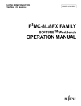
These commands automatically call up the tools composing the C compiler (preprocessor and
compiler), and provides control over C source file compiling. The C compiler structure is shown
in Figure 1.1-1.
C source file
Standard
header file
Preprocessor
(cpp)
Message file
Preprocessed
C source file
Message file
Compiler
(ccom)
Stack use
information file
Assembler
source file
Figure 1.1-1 C Compiler Structure
In the subsequent sections, the C compiler translation process is explained using commands.
For the details of the command function specifications, see Chapter 3, Operation.
2
1.2 BASIC PROCESS OF COMMANDS
1.2
BASIC PROCESS OF COMMANDS
The basic process of commands is described below.
Each MCU has the following commands.
● fcc911s: For FR family
● fcc907s: For F2MC-16L/16LX/16/16H/16F family
● fcc896s: For F2MC-8L family
■ fcc907s Command Basic Process
The fcc907s command basically generates an object file from an described C source file. The
command regards any file with a .c extension as a C source file.
An example of using the fcc907s command is given below, where % is the command prompt.
[Example 1]
%
fcc907s
-cpu
MB90F553A
file.c
At the input given above, the command regards file.c as a C source file and, if no error is
detected, generates an object file (file.obj) in the current directory.
[Example 2]
%
fcc907s
-o
outfile
-cpu
MB90F553A
file.c
At the input given above, the command generates an object file (outfile). The command
operation process can be controlled by specifying options, such as -o.
■ fcc911s Command Basic Process
The fcc911s command basically generates an absolute file from an described C source file.
The command regards any file with a .c extension as a C source file.
An example of using the fcc911s command is given below, where % is the command prompt.
[Example 1]
%
fcc911s
-cpu
MB91F154
file.c
At the input given above, the command regards file.c as a C source file and, if no error is
detected, generates an absolute file (file.abs) in the current directory.
[Example 2]
%
fcc911s
-o
outfile
-cpu
MB91F154
file.c
At the input given above, the command generates an absolute file (outfile). The
command operation process can be controlled by specifying options, such as -o.
3
CHAPTER 1 GENERAL
■ fcc896s Command Basic Process
The fcc896s command basically generates an absolute file from an described C source file.
The command regards any file with a .c extension as a C source file.
An example of using the fcc896s command is given below, where % is the command prompt.
[Example 1]
%
fcc896s
-cpu
MB89P935B
file.c
At the input given above, the command regards file.c as a C source file and, if no error is
detected, generates an absolute file (file.abs) in the current directory.
[Example 2]
%
fcc896s
-o
outfile
-cpu
MB89P935B
file.c
At the input given above, the command generates an absolute file (outfile). The
command operation process can be controlled by specifying options, such as -o.
■ Options for Compiling Process Control
• -P option
When the -P option is specified, the command calls up the preprocessor only and performs
preprocessing to generate a preprocessed C source file in the current directory. The
extension of the generated file is changed to .i.
• -S option
When the -S option is specified, the command calls up the preprocessor and compiler and
performs preprocessing and compiling to generate an assembler source file in the current
directory. The extension of the generated file is changed to .asm.
• -c option (only for fcc911s and fcc896s commands)
When the -c option is specified, the command calls up the preprocessor, compiler, and
assembler and performs preprocessing, compiling, and assembling to generate an object file
in the current directory. The extension of the generated file is changed to . obj. Note that
this option cannot be specified for the fcc907s command.
• -o option
When the -o option is specified, the command generates the file specified in the command
line as a result of processing.
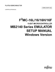
Output files generated according to the above options specifying can be used as the input files
for the fcc907s command. The input files and output files generated by options are shown in
Figures 1.2-1 and 1.2-2.
4
1.2 BASIC PROCESS OF COMMANDS
-P
file.c
Preprocessor
file.i
Compiler
-P -o
-S
fcc907s command
file.asm
-S -o
file.i
Specified file
file.asm
Specified file
file.c
Assembler
-o
Specified file
Figure 1.2-1 Relationship between Input Files and Output Files Generated by Options
(fcc907s Command)
-P
file.c
Preprocessor
file.i
Compiler
-P -o
-S
fcc911s command
fcc896s command
-S -o
-c
file.asm
Assembler
file.obj
Linker
-c -o
file.i
Specified file
file.asm
Specified file
file.obj
Specified file
file.abs
-o
Specified file
Figure 1.2-2 Relationship between Input Files and Output Files Generated by Options
(fcc911s and fcc896s Commands)
5
CHAPTER 1 GENERAL
1.3
C COMPILER BASIC FUNCTIONS
The C compiler functions are described below.
● Header file search
● Coordination with symbolic debugger
● Optimization
The symbolic debugger is a support tool for analyzing a program created in C
language.
■ Header File Search
The header file can be acquired using the C program #include instruction. When the absolute
pathname is specified, the header file enclosed within angular brackets (<>) is searched for in
the directory specified by absolute pathname. When the absolute pathname is not specified,
the standard directory is searched.
The standard header file is supplied by the C compiler.
The header file enclosed by double quotation marks (") is searched for in a directory specified
by the absolute pathname. If the absolute pathname is not specified, such a header file is
searched for in a directory having a file containing a #include line. If the header file is not
found in a directory having a file containing a #include line, the standard directory is searched
next.
The -I option makes it possible to add a directory for header file search.
[Example]
%
fcc907s
-cpu
MB90F553A -I
%
fcc911s
-cpu
MB91F154 -I
%
fcc896s
-cpu
MB89P935B -I
../include
../include
../include
file.c
file.c
file.c
At the input given above, the command searches for the header file enclosed within angular
brackets in the order shown below.
1. ../include
2. Standard directory
The header file enclosed by double quotation marks is searched for in the order shown below.
1. Current directory having a file containing a #include line
2. ../include
3. Standard directory
The -I option can be specified a desired number of times. When it is specified two or more
times, search operations are conducted in the specified order.
6
1.3 C COMPILER BASIC FUNCTIONS
■ Coordination with Symbolic Debugger
When the -g option is specified, the compiler generates the debug information to be used by
the symbolic debugger. When such information is generated, C language level debugging can
be accomplished within the symbolic debugger. Two types of symbol debuggers are available;
simulator debugger and emulator debugger.
When the optimization option is specified, the compiler attempts to ensure good code
generation by changing the computation target position and eliminating computations that are
judged to be unnecessary. To minimize the amount of data exchange with memory, the
compiler tries to retain data within a register. It is therefore conceivable that a break point
positioned in a certain line may fail to cause a break or that currently monitored certain address
data may fail to vary with the expected timing. It also well to remember that the debug data will
not be generated for an unused local variable or a local variable whose area need not be
positioned in a stack as a result of optimization.
Debugging must be conducted with the above considerations taken into account.
■ Optimization
When the -O option is specified, the compiler generates an object subjected to general-purpose
optimization.
7
CHAPTER 1 GENERAL
8
CHAPTER 2
SETUP OF SYSTEM EMVIRONMENT
BEFORE USING C COMPILER
This chapter describes the C compiler operating environment variables (for the setting
of environment variables, refer to the manual for each operating system). All the
environment variables can be omitted.
For the supply style, refer to the C Compiler Installation Manual.
The Windows95/WindowsNT version permits the use of long file names for the
directories to be set up as environment variables. For the characters applicable to
long file names, see 3.3, File Names and Directory Names.
[Setup Example]
set TMP=c:Fujitsu MCU tool
For environment variable setup, do not use double quotation marks (").
2.1
FETOOL
2.2
LIB911/LIB896
2.3
OPT907/OPT911/OPT896
2.4
INC907/INC911/INC896
2.5
TMP
2.6
FELANG
9
CHAPTER 2 SETUP OF SYSTEM EMVIRONMENT BEFORE USING C COMPILER
2.1
FETOOL
Specify the installation directory for the development environment.
■ FETOOL
[General Format 1] For UNIX OS
setenv FETOOL
Installation directory
[General Format 2] For Windows
set FETOOL=Installation directory
The driver accesses the compiler, message file, include file, and other items via the path
specified by FETOOL.
When FETOOL setup is not completed, the parent directory for the directory where the activated
command exists (the /.. position of the directory where the command exists) is regarded as the
installation directory.
No more than one directory can be specified.
[Example] For UNIX OS
setenv FETOOL /usr/local/softune
[Example] For Windows
set FETOOL=c:\softune
10
2.2 LIB911/LIB896
2.2
LIB911/LIB896
Specify the directory that contains the library to which the fcc911s or fcc896s
command is linked by default.
■ LIB911/LIB896
[General Format 1] For UNIX OS
setenv LIB911
Library directory [: Directory 2 ...]
setenv LIB896
Library directory [: Directory 2 ...]
[General Format 2] For Windows
set LIB911=Library directory [; Directory 2 ...]
set LIB896=Library directory [; Directory 2 ...]
Specify the directory to which linking is effected by default.
If LIB911 setup is not completed, the directory placed at an offset from the directory specified
by FETOOL (${FETOOL}/lib/911 or ${FETOOL}/lib/896) is regarded as the default
library directory.
When two or more directories are specified, ":" (UNIX) or ";" (Windows) is interpreted as the
directory name delimiter.
[Example] For UNIX OS
setenv LIB911 /usr/local/softune/lib/911
setenv LIB896 /usr/local/softune/lib/896
[Example] For Windows
set LIB911=d:\softune\lib\911
set LIB896=d:\softune\lib\896
11
CHAPTER 2 SETUP OF SYSTEM EMVIRONMENT BEFORE USING C COMPILER
2.3
OPT907/OPT911/OPT896
Specify the directory for the default option file to be used by the command. For the
fcc907s command, set OPT907. For the fcc911s command, set OPT911. For the
fcc896s command, set OPT896.
■ OPT907/OPT911/OPT896
[General Format 1] For UNIX OS
setenv OPT907
Default option file directory
setenv OPT911
Default option file directory
setenv OPT896
Default option file directory
[General Format 2] For Windows
set OPT907=Default option file directory
set OPT911=Default option file directory
set OPT896=Default option file directory
Specify the directory for the default option file to be used by the driver.
If OPT907/OPT911/OPT896 setup is not completed, the directory placed at an offset from the
directory specified by FETOOL (${FETOOL}/lib/907, ${FETOOL}/lib/911, or
${FETOOL}/lib/896) is regarded as the default option file directory.
No more than one directory can be specified.
[Example] For UNIX OS
setenv OPT907 /usr/local/softune/lib/907
setenv OPT911 /usr/local/softune/lib/911
setenv OPT896 /usr/local/softune/lib/896
[Example] For Windows
set OPT907=c:\softune\lib\907
set OPT911=c:\softune\lib\911
set OPT896=c:\softune\lib\896
12
2.4 INC907/INC911/INC896
2.4
INC907/INC911/INC896
Specify the directory where a standard header file search is to be conducted by the
command. For the fcc907s command, set INC907. For the fcc911s command, set
INC911. For the fcc896s command, set INC896.
■ INC907/INC911/INC896
[General Format 1] For UNIX OS
setenv INC907
Standard include directory
setenv INC911
Standard include directory
setenv INC896
Standard include directory
[General Format 2] For Windows
set INC907=Standard include directory
set INC911=Standard include directory
set INC896=Standard include directory
Specify the directory where the standard header file is to be searched for. The directory
specified by INC907/INC911/INC896 is regarded as the standard include directory.
If INC907C/INC911 setup is not completed, the directory placed at an offset from the directory
specified by FETOOL (${FETOOL}/lib/907/include, ${FETOOL}/lib/911/include, or
${FETOOL}/lib/896/include) is regarded as the standard header file directory.
No more than one directory can be specified.
[Example] For UNIX OS
setenv INC907 /usr/local/softune/lib/907/include
setenv INC911 /usr/local/softune/lib/911/include
setenv INC896 /usr/local/softune/lib/896/include
[Example] For Windows
set INC907=c:\softune\lib\907\include
set INC911=c:\softune\lib\911\include
set INC896=c:\softune\lib\896\include
13
CHAPTER 2 SETUP OF SYSTEM EMVIRONMENT BEFORE USING C COMPILER
2.5
TMP
Specify the directory for the temporary file to be used by the C compiler.
■ TMP
[General Format 1] For UNIX OS
setenv TMP
Temporary directory
[General Format 2] For Windows
set TMP=Temporary directory
Specify the working directory for creating the temporary file to be used by the C compiler.
If TMP setup is not completed, the temporary file is created in the /tmp directory for UNIX OS or
in the current directory for Windows.
No more than one directory can be specified.
[Example] For UNIX OS
setenv TMP /usr/tmp
[Example] For Windows
set TMP=c:\tmp
14
2.6 FELANG
2.6
FELANG
Specify the code for messages.
■ FELANG
[General Format 1] For UNIX OS
setemv FELANG
Message code
[General Format 2] For Windows
set FELANG=Message code
Specify the message code. The following codes can be specified.
• ASCII: Outputs messages in ASCII code
The generated messages are in English.
Select this code for a system without a Japanese language environment.
• EUC: Outputs messages in EUC code
The generated messages are in Japanese.
• SJIS: Outputs messages in SHIFT JIS code
The generated messages are in Japanese.
If FELANG setup is not completed, the ASCII code is considered to be selected.
[Example] For UNIX OS
setenv FELANG EUC
[Example] For Windows
set FELANG=SJIS
15
CHAPTER 2 SETUP OF SYSTEM EMVIRONMENT BEFORE USING C COMPILER
16
CHAPTER 3
OPERATION
This chapter describes the command function specifications.
3.1
COMMAND LINE
3.2
COMMAND OPERANDS
3.3
FILE NAMES AND DIRECTORY NAMES
3.4
COMMAND OPTIONS
3.5
DETAILS OF OPTIONS
3.6
OPTION FILES
3.7
MESSAGES GENERATED IN TRANSLATION PROCESS
17
CHAPTER 3 OPERATION
3.1
COMMAND LINE
The command line format is shown below.
● fcc907s [options] operands
● fcc911s [options] operands
● fcc896s [options] operands
■ Command Line
Options and operands can be specified in the command line. They can be specified at any
position within the command line. Two or more options and operands can be specified.
Options can be omitted.
Option and operand entries are to be delimited by a blank character string. The command
recognizes the options and operands in the order shown below.
1.An entry beginning with a hyphen (-) is first recognized as an option. The subsequent
character string is interpreted to determine the option type.
2.As regards an option having an argument, the subsequent character string is regarded
as the argument.
3.The remaining entries in the command line are recognized as operands.
[Example]
%fcc907s file1.c -S -I /home/myincs file2.c
%fcc911s file1.c -S -I /home/myincs file2.c
%fcc896s file1.c -S -I /home/myincs file2.c
At first, -S and -I are regarded as options. Since the -I option has an argument, the
subsequent character string /home/myincs is regarded as the argument. The remaining
entries (file1.c and file2.c) are regarded as operands.
Options
: -S, -I /home/myincs
Operands : file1.c, file2.c
■ Command Process
The command calls up the preprocessor, compiler, assembler, and linker for all input files in the
order of their specifying, and performs preprocessing, compiling, assembling, and linking. The
results are output into files which are named by replacing the input file extensions with .obj.
[Example]
%fcc907s file1.c file2.c file3.c -cpu MB90F553A
Files named file1.c, file2.c, and file3.c are subjected to preprocessing, compiling,
and assembling so that files named file1.obj, file2.obj, and file3.obj are
generated.
%fcc911s file1.c file2.c file3.c -cpu MB91F154
%fcc896s file1.c file2.c file3.c -cpu MB89P935B
Files named file1.c, file2.c, and file3.c are subjected to preprocessing, compiling,
assembling, and linking so that files named file1.abs are generated.
18
3.2 COMMAND OPERANDS
3.2
COMMAND OPERANDS
One or more input files can be specified as operands.
■ Command Operands
The command determines the file type according to the input file extension and performs an
appropriate process to suit the file type.
The extension cannot be omitted.
• File Specifying
C source files, preprocessed C source files, assembler source files, and object files can be
specified as operands.
• File Extension
The relationship between input file extensions and fcc907s command processes is shown
in Table 3-2-1. Note, however, that the associated process may be inhibited depending on
the option specifying.
Table 3.2-1 Relationship between Extensions and Command Processes
Extension
Command Process
.c
The file having this extension is regarded as a C source file and subjected to
preprocessing and subsequent processes.
.i
The file having this extension is regarded as a preprocessed C source file
and subjected to compiling and subsequent processes.
.asm
The file having this extension is regarded as a compiled assembler source
file and subjected to assembling and subsequent processes.
.obj
The file having this extension is regarded as an assembled object file and
subjected to linking and subsequent processes. For this type of file, the
fcc907s command does nothing.
.abs
The file having this extension is regarded as a linked absolute file, and an
error output is generated. No absolute file can be specified.
[Example]
%fcc907s file1.c file2.i -cpu MB90F553A
A file named file1.c is subjected to preprocessing, compiling, and assembling. A file
named file2.i is then subjected to compiling and assembling to generate files named
file1.obj and file2.obj.
%fcc911s file1.c file2.i -cpu MB91F154
%fcc896s file1.c file2.i -cpu MB89P935B
A file named file1.c is subjected to preprocessing, compiling, and assembling. A file
named file2.i is then subjected to compiling, assembling, and linking, in order named, to
generate a file named file1.abs.
19
CHAPTER 3 OPERATION
3.3
FILE NAMES AND DIRECTORY NAMES
The following characters are applicable to file names and directory names.
■ File Names and Directory Names
• Windows95/WindowsNT version
Alphanumeric characters, symbols except \, /, :, *, ?, ", <, >, and |, Shift-JIS kanji codes,
and Shift-JIS 1-byte kana codes.
When long file name is specified as option and operand, it should be enclosed by double
quotation marks ("). However, do not use double quotation marks at setup environment
variable with this file name.
• Other Versions
Underbar (_) and alphanumeric characters (however, the first character must be the
underbar or alphabetical character).
• Module Name
The module name is based on a file name. It is formed by an underbar (_) and
alphanumeric characters (The first character must be alphabetic with an underbar). If other
characters are used for the file name, the characters that cannot be used for the module
name are converted to underbars. File names allowing identical module names should not
be used.
20
3.4 COMMAND OPTIONS
3.4
COMMAND OPTIONS
This section describes the command options.
■ Option Syntax
The option consists of a hyphen (-) and one or more characters following the hyphen. Some
options have an argument. A blank character string must be positioned between an option and
an argument. The command options cannot be grouped for purposes of specifying. Grouping
is a technique of specifying which, for instance, uses a -Sg form to specify both the -S option
and -g option.
■ Multiple Specifying of Same Option
If the same option is specified more than one time, only the last-specified option in the
command line is assumed to be valid.
[Example]
%fcc907s -o outfile file.c -o outobj -cpu MB90F553A
%fcc911s -o outfile file.c -o outobj -cpu MB91F154
%fcc896s -o outfile file.c -o outobj -cpu MB89P935B
The resultant output file name will be outobj.
• Options that are significant when specified more than one time
-D
-f
-I
-INF
-K
-L
-l
-ra
-ro
-sc
-T
-U
-x
-Y
When the above options are specified more than one time, see details of options.
■ Position within Command Line
The option's position within the command line does not have a special meaning. Options are
interpreted in the same manner no matter where in the command line they are specified.
[Example]
1) %fcc907s -C -E file1.c file2.c -cpu MB90F553A
2) %fcc907s file1.c -E file2.c -C -cpu MB90F553A
1) %fcc911s -C -E file1.c file2.c -cpu MB91F154
2) %fcc911s file1.c -E file2.c -C -cpu MB91F154
1) %fcc896s -C -E file1.c file2.c -cpu MB89P935B
2) %fcc896s file1.c -E file2.c -C -cpu MB89P935B
The same processing operations are performed for cases 1) and 2).
■ Exclusiveness and Dependency
Some options are mutually exclusive or dependent on each other. For option exclusiveness
and dependency, see details of options.
21
CHAPTER 3 OPERATION
■ Case Sensitiveness
As regards the options, their upper-case and lower-case characters are different from each
other. For example, the -O option is different from the -o option. However, the upper- and
lower-case characters of suboptions are not differentiated from each other. For example, the
-K eopt option is considered in the same as the -K EOPT option. The suboptions are the
character strings that follow the -K option or -INF option.
22
3.4 COMMAND OPTIONS
3.4.1 List of Command Options
When executed without argument specifying, the command outputs an option list to
the standard output. The options for the command are listed in Tables 3.4-1 to 3.4-4.
The options listed in the tables can be recognized by the command.
■ List of Command Options
Table 3.4-1 List of Command Options
Specifying Format
Function
-B
Allows the C++ type comments(//)
-C
Leaves a comment in the preprocessing result
-cmsg
Outputs the compiling process end message to the standard output
-cpu
MB number
Specifies the MB number of the CPU to be used
-cwno
Sets end code to 1 when warning given
-D name[=[tokens]]
Defines the macro name
-E
Performs preprocessing only and outputs the result to the standard output
-f filename
Specifies the option file
-g
Adds to the object the information necessary for debugging
-H
Outputs the acquired header file pathname to the standard output
-help
Outputs the option list to the standard output
-I dir
Specifies the directory for head file search
-INF LIST
Generates the assemble list
-INF {SRCIN|LINENO}
Inserts the associated C source information as a comment into the assembler source
-INF STACK[=filename]
Generates the stack use amount data
-J {a|c}
Specifies the specification level of the language to be interpreted by the compiler
-K {DCONST|FCONST}
Specifies the type of a real constant without a suffix
-K EOPT
Effects optimization for changing the arithmetic operation evaluation procedure
-K LIB
Recognizes the standard function operation and implements in-line expansion/substitution
for other functions
-K NOALIAS
Effects optimization on the presumption that differing pointers do not indicate the same
area
-K NOINTLIB
Effects no in-line expansion for interrupt related functions
-K NOUNROLL
Inhibits loop unrolling
-K NOVOLATILE
Does not consider __io qualifier variables to be volatile
-K REALOS
Effects in-line expansion for the ITRON system call function
-K {SIZE|SPEED}
Selects optimization with emphasis placed on the size and execution speed
-K {UCHAR|SCHAR}
Specifies the mere char sign handling
-K {UBIT|SBIT}
Specifies the mere int bit field sign handling
-kanji {SJIS|EUC}
Specifies kanji code used in program
-O level
Gives instructions for general-purpose optimization
23
CHAPTER 3 OPERATION
Table 3.4-1 List of Command Options (Continued)
Specifying Format
Function
-o pathname
Outputs the result to the pathname
-P
Performs preprocessing only and outputs the result to .i
-S
Performs processes up to compiling and outputs the result to .asm
-s defname=newname
[, attr [, address]]
Changes the section name
-T item, arg1 [, arg2 ...]
Passes arguments to the tool
-U name
Cancels the macro name definition
-V
Outputs the executed compiler tool version information to the standard output
-w level
Specifies the warning message output level
-Xdof
Inhibits the default option file read operation
-x func [, func2 ...]
Specifies the in-line expansion of functions
-xauto [size]
Specifies the in-line expansion of the functions whose logical line count is not less than
size
-Y item, dir
Changes the item position to dir
Table 3.4-2 List of fcc907s Command Options
Specifying Format
Function
-div905
Specifies the DIV/DIVW instruction is generated
-K ADDSP
Releases actual argument areas altogether
-K ARRAY
Optimization of array element access code.
-pack
Packing of struct and union menbers.
-model {SMALL|MEDIUM|COMPACT|LARGE}
Specifies the memory model
-ramconst
Specifies that the mirror function will not be used
-varorder {SORT|NORMAL}
Specifies the rule of arrangement of external variables and static variables
in section
24
3.4 COMMAND OPTIONS
Table 3.4-3 List of fcc911s Command Options
Specifying Format
Function
-c
Performs processes up to assembling and outputs the result to .obj
-e name
Specifies the entry of a program
-K {A1|A4}
Specifies the minimum boundary alignment value for static data
-K {SCHEDULE|NOSCHEDULE}
Specifies the recall of the scheduler
-K {SARG|DARG}
Specifies the argument area acquisition type
-K {SHORTADDRESS[= {CODE|DATA}]
|LONGADDRESS[= {CODE|DATA}]}
Specifies the external symbol handling type
-L path1 [, path2 ...]
Specifies the library path
-l lib1 [, lib2 ...]
Specifies the library file name
-m
Outputs a map file at the time of linking
-ra name = start/end
Specifies the RAM area
-ro name = start/end
Specifies the ROM area
-sc param
Specifies the section arrangement
-startup file
Specifies the startup file name
-varorder {SORT|NORMAL}
Specifies the rule of arrangement of external variables and static variables
in section
Table 3.4-4 List of fcc896s Command Options
Specifying Format
Function
-c
Performs processes up to assembling and outputs the result to .obj
-e name
Specifies the entry of a program
-L path1 [, path2 ...]
Specifies the library path
-l lib1 [, lib2 ...]
Specifies the library file name
-K ADDSP
Releases actual argument areas altogether
-K ARRAY
Optimization of array element access code.
-m
Outputs a map file at the time of linking
-ra name = start/end
Specifies the RAM area
-ro name = start/end
Specifies the ROM area
-sc param
Specifies the section arrangement
-startup file
Specifies the startup file name
25
CHAPTER 3 OPERATION
3.4.2 List of Command Cancel Options
The cancel options for the command are listed in Tables 3.4-5 to 3.4-8. The listed
options are used to cancel command options on an individual basis.
■ List of Command Cancel Options
Table 3.4-5 List of Command Cancel Options
Specifying Format
26
Function
-XB
Cancels the -B option
-XC
Cancels the -C option
-Xcmsg
Cancels the -cmsg option
-Xcwno
Cancels the -cwno option
-Xf
Cancels the -f option
-Xg
Cancels the -g option
-XH
Cancels the -H option
-Xhelp
Cancels the -help option
-XI
Cancels the -I option
-INF NOLINENO
Cancels the LINENO suboption
-INF NOLIST
Cancels the LIST suboption
-INF NOSRCIN
Cancels the SRCIN suboption
-INF NOSTACK
Cancels the STACK suboption
-K ALIAS
Cancels the NOALIAS suboption
-K INTLIB
Cancels the NOINTLIB suboption
-K NOEOPT
Cancels the EOPT suboption
-K NOLIB
Cancels the LIB suboption
-K NOREALOS
Cancels the REALOS suboption
-K UNROLL
Cancels the NOUNROLL suboption
-K VOLATILE
Cancels the NOVOLATILE suboption
-Xo
Cancels the -o option
-Xs
Cancels the -s option
-XT item
Cancels the -T item specifying
-XV
Cancels the -V option
-Xx
Cancels the -x option
-Xxauto
Cancels the -xauto option
-XY item
Cancels the -Y item specifying
3.4 COMMAND OPTIONS
Table 3.4-6 List of fcc907s Command Cancel Options
Specifying Format
Function
-K NOADDSP
Cancels the ADDSP suboption
-K NOARRAY
Cancels the ARRAY suboption
-Xpack
Cancels the -pack option
-Xdiv905
Cancels the -div905 option
-Xramconst
Cancels the -ramconst option
Table 3.4-7 List of fcc911s Command Cancel Options
Specifying Format
Function
-Xe
Cancels the -e option
-XL
Cancels the -L option
-Xl
Cancels the -l option
-Xm
Cancels the -m option
-Xra
Cancels the -ra option
-Xro
Cancels the -ro option
-Xsc
Cancels the -sc option
-Xstartup
Cancels the -startup option
Table 3.4-8 List of fcc896s Command Cancel Options
Specifying Format
Function
-Xe
Cancels the -e option
-K NOADDSP
Cancels the ADDSP suboption
-K NOARRAY
Cancels the ARRAY suboption
-XL
Cancels the -L option
-Xl
Cancels the -l option
-Xm
Cancels the -m option
-Xra
Cancels the -ra option
-Xro
Cancels the -ro option
-Xsc
Cancels the -sc option
-Xstartup
Cancels the -startup option
27
CHAPTER 3 OPERATION
3.5
DETAILS OF OPTIONS
This section details the options.
■ Translation Control Related Options
The translation control related options are related to preprocessor, compiler, assembler, and
linker call control.
■ Preprocessor Related Options
The preprocessor related options are related to preprocessor operations.
■ Data Output Related Options
The data output related options are related to the command, preprocessor, and compiler data
outputs.
■ Language Specification Related Options
The language specification related options are related to the specification of the language to be
recognized by the compiler.
■ Optimization Related Options
The optimization related options are related to the optimization to be effected by the compiler.
■ Output Object Related Options
The output object related options are related to the output object format.
■ Debug Information Related Options
The debug information related options are related to the debug information to be referenced by
the symbolic debugger.
■ Command Related Options
The command related options are related to the other tools recalled by commands.
■ Linkage Related Options
The linkage related options are related to linkage.
■ Option File Related Options
The option file related options are related to option files.
28
3.5 DETAILS OF OPTIONS
3.5.1 Translation Control Related Options
This section describes the options related to preprocessor, compiler, assembler, and
linker call control.
■ Translation Control Related Options
The priorities of the translation control related options are defined as follows. They are not
related to the order of specifying.
-E > -P > -S > -c
The translation control related option exclusiveness is shown in Table 3.5-1.
Table 3.5-1 Translation Control Related Option Exclusiveness
Specified Option
Option Invalidated
-E
-S and -c
-P
-S and -c
-S
-c
-c
None
If the -E and -P options are specified simultaneously, see the explanation below. The -c
option cannot be used with the fcc907s command.
The translation control related options are detailed below.
❍ -E
This option subjects all files to preprocessing only and outputs the result to the standard
output. The output result contains the preprocessing instruction generated by the
preprocessor, which is necessary for the compiler. The information targets for the
preprocessing instruction generated by the preprocessor are the #line and #pragma
instructions. If the -P option is specified together with the -E option, the preprocessing
instruction generated by the preprocessor is inhibited. If the input file is not a C source file, the
-E option does not do anything.
[Example]
%fcc907s -E -cpu MB90F553A sample.c
%fcc911s -E -cpu MB91F154 sample.c
%fcc896s -E -cpu MB89P935B sample.c
The sample.c preprocessing result is output to the standard output.
❍ -P
This option subjects a C source file to preprocessing only and outputs the result to the file
whose extension is changed to .i. Unlike the cases where the -E option is specified, the
output result does not contain the preprocessing instruction generated by the preprocessor. If
the input file is not a C source file, the -P option does not do anything.
29
CHAPTER 3 OPERATION
[Example]
%fcc907s -P -cpu MB90F553A sample.c
%fcc911s -P -cpu MB91F154 sample.c
%fcc896s -P -cpu MB89P935B sample.c
The sample.c preprocessing result is output to the sample.i.
❍ -S
This option performs processes up to compiling and outputs the resultant assembler source to
file extension changed to .asm. If the input is neither a C source file nor a preprocessed C
source file, the -S option does not do anything.
[Example]
%fcc907s -S -cpu MB90F553A sample.c
%fcc911s -S -cpu MB91F154 sample.c
%fcc896s -S -cpu MB89P935B sample.c
The sample.c preprocessing and compiling process result are output to the sample.asm.
❍ -c
This option performs processes up to assembling and outputs the resultant object to file
extension changed to .obj. If the input file is an object file, the -c option does not do anything.
The option cannot be used with the fcc907s command.
[Example]
%fcc911s -c -cpu MB91F154 sample.c
%fcc896s -c -cpu MB89P935B sample.c
The sample.c preprocessing and compiling process result is output to the sample.obj.
The relationship among file types, translation control related options, and processes is shown in
Table 3.5-2.
Table 3.5-2 Relationship Among File Types, Translation Control Related Options,
and Processes
Option File Type (Extension)
-E
-P
-S
-c
Nothing Specified
C source file (.c)
P
P
P and C
P, C and A
P, C, A and L
Preprocessed C source file (.i)
—
—
C
C and A
C, A and L
Assembler source file (.asm)
—
—
—
A
A and L
Object file (.obj)
—
—
—
—
L
P:
C:
A:
L:
30
Preprocessing
Compiling
Assembling
Linking
3.5 DETAILS OF OPTIONS
The fcc907s command does not call linker.
[Example]
%fcc907s -E file1.c file2.i -cpu MB90F553A
%fcc911s -E file1.c file2.i -cpu MB91F154
%fcc896s -E file1.c file2.i -cpu MB89P935B
Subjects a file named file1.c to preprocessing only and outputs the result to the standard
output. Performs nothing for a file named file2.i.
%fcc907s -E file1.c file2.i file3.asm -cpu MB90F553A
%fcc911s -E file1.c file2.i file3.asm -cpu MB91F154
%fcc896s -E file1.c file2.i file3.asm -cpu MB89P935B
Subjects a file named file1.c to preprocessing and compiling and a file named file2.i to
compiling. Performs nothing for a file named file3.asm. As a result, files named file1.asm
and file2.asm are generated in the current directory.
31
CHAPTER 3 OPERATION
3.5.2 Preprocessor Related Options
This section describes the options related to preprocessor operations. If the
preprocessor is not called, the preprocessor related options are invalid.
■ Preprocessor Related Options
The preprocessor related options are detailed below.
❍ -B
❍ -XB
The -B option allows C++ style comments. When specifying this option, // style in addition to /*
*/ style can be used.
The -XB option cancels the -B option.
❍ -C
❍ -XC
The -C option retains all comments except those which are in the preprocessing instruction line
as the preprocessing result. If the option is not specified, the comments are replaced by one
blank character.
The -XC option cancels the -C option.
[Output Example]
• Input:
/* Comment */
void func(void){}
• Operation:
fcc907s -C -E -cpu MB90F553A sample.c
fcc911s -C -E -cpu MB91F154 sample.c
fcc896s -C -E -cpu MB89P935B sample.c
• Output:
# 1 "test5.c"
/* Comment */
void func(void){}
❍ -D name [=[tokens]]
This option defines the macro name with the tokens used as the macro definition. The option
is equivalent to the following #define instruction.
#define name
tokens
If =tokens entry is omitted, the value 1 is given as the tokens value. If the tokens entry is
omitted, the specified lexeme is deleted from the source file. The error related to the -D option
is the same as the error related to the #define instruction. This option can be specified more
than one time.
32
3.5 DETAILS OF OPTIONS
[Example]
%fcc907s -D os=m -D sys file.c -cpu MB90F553A
%fcc911s -D os=m -D sys file.c -cpu MB91F154
%fcc896s -D os=m -D sys file.c -cpu MB89P935B
In a file named file.c, processing is conducted on the assumption that the macro
definitions for os and sys are m and 1, respectively.
❍ -H
❍ -XH
The -H option outputs to the standard output the header file pathnames acquired during
preprocessing. The pathnames are sequentially output, one for each line, in the order of
acquisition. If there are any two exactly the same pathnames, only the first one will be output.
When this option is specified, the command internally sets up the -E option to subjects all files
to preprocessing only. However, the preprocessing result will not be output.
The -XH option cancels the -H option.
[Output Example]
• Input:
#include <stdio.h>
#include "head.h"
• Operation:
fcc907s -H -cpu MB90F553A sample.c
• Output:
/usr/softune/lib/907/include/stdio.h
./head.h
• Operation:
fcc911s -H -cpu MB91F154 sample.c
• Output:
/usr/softune/lib/911/include/stdio.h
./head.h
• Operation:
fcc896s -H -cpu MB89P935B sample.c
• Output:
/usr/softune/lib/896/include/stdio.h
./head.h
❍ -I dir
❍ -XI
The -I option changes the manner of header file search so that the directory specified by dir
will be searched prior to the standard directory. The standard directory is ${INC907}
(fcc907s command), ${INC911} (fcc911s command), or ${INC896} (fcc896s
command).
33
CHAPTER 3 OPERATION
This option can be specified more than one time. The search will be conducted in the order of
specifying. When the option is specified, the header file search will be conducted in the
following directories in the order shown below.
• Header file enclosed within angular brackets (< >)
1.Directory specified by the -I option
2.Standard directory
34
3.5 DETAILS OF OPTIONS
• Header file enclosed by double quotation marks (")
1.Directory having a file containing the #include line
2.Directory specified by the -I option
3.Standard directory
If a header file is specified by specifying its absolute path name, only the directory specified by
the specified absolute path name will be searched. If any nonexistent directory is specified, this
option is invalid.
The -XI option cancels the -I option.
❍ -U name
This option cancels the macro name definition specified by -D. The option is equivalent to the
following #undef instruction.
#undef name
If the same name is specified by the -D and -U options, the name definition will be canceled
without regard to the order of option specifying.
This option can be specified more than one time.
The error related to the -U option is the same as the error related to the #undef instruction.
[Example]
%fcc907s -U m -D n -D m file.c -cpu MB90F553A
%fcc911s -U m -D n -D m file.c -cpu MB91F154
%fcc896s -U m -D n -D m file.c -cpu MB89P935B
This will cancel the macro m definition specified by the -D option.
35
CHAPTER 3 OPERATION
3.5.3 Data Output Related Options
This section describes the options related to the command, preprocessor, and
compiler data outputs.
■ Data Output Related Options
❍ -cmsg
This option outputs the compiling process completion message.
[Example]
• Operation:
fcc907s -cmsg -S -cpu MB90F553A sample.c
fcc911s -cmsg -S -cpu MB91F154 sample.c
fcc896s -cmsg -S -cpu MB89P935B sample.c
• Output:
COMPLETED C Compile, FOUND NO ERROR : sample.c
❍ -cwno
This option sets the end code to 1 when a warning-level error occurs. When the option is not
specified, the end code is 0.
❍ -help
❍ -Xhelp
The -help option outputs the option list to the standard output. The -Xhelp option cancels the
-help option.
[Example]
%fcc907s -help
%fcc911s -help
%fcc896s -help
Various command option lists are output to the standard output.
❍ -INF LINENO
❍ -INF NOLINENO
The -INF LINENO option inserts C source file line numbers into the assembler source file as
comments. The LINENO suboption cannot be specified simultaneously with the SRCIN suboption.
The NOLINENO suboption cancels the LINENO suboption.
36
3.5 DETAILS OF OPTIONS
[Output Example]
• Input:
void func(void){}
• Operation:
fcc907s -INF lineno -S -cpu MB90F553A sample.c
• Output:
_func:
LINK
;;;;
#0
a.c, line 1
UNLINK
RET
• Operation:
fcc911s -INF lineno -S -cpu MB91F154 sample.c
• Output:
_func:
;;;;
ST
RP, @-SP
ENTER
#4
a.c, line 1
L_func:
LEAVE
LD
@SP+, RP
RET
• Operation:
fcc896s -INF lineno -S -cpu MB89P935B sample.c
• Output:
_func:
;;;;
e.c, line 1
L_func:
RET
❍ -INF LIST
❍ -INF NOLIST
The -INF LIST option generates a file in the current directory and outputs the assemble list.
The name of the generated file is determined by changing the source file name extension to
.lst. Since the assemble list is generated at assembling, it is not generated when assembling
is not conducted. For the details of the assemble list, refer to the Assembler Manual.
The NOLIST suboption cancels the LIST suboption.
37
CHAPTER 3 OPERATION
[Example]
%fcc907s -INF list -c -cpu MB90F553A sample.c
%fcc911s -INF list -c -cpu MB91F154 sample.c
%fcc896s -INF list -c -cpu MB89P935B sample.c
The sample.c preprocessing, compiling, and assembling process result are output to the
sample.obj, and the resulting assemble list is output to the sample.lst.
❍ -INF SRCIN
❍ -INF NOSRCIN
The -INF SRCIN option inserts a C source file into the assembler source file as a comment.
The SRCIN suboption cannot be specified simultaneously with the LINENO suboption.
The NOSRCIN suboption cancels the SRCIN suboption.
[Output Example]
• Input:
void func(void){}
• Operation:
fcc907s -INF srcin -S -cpu MB90F553A sample.c
• Output:
_func:
LINK
;;;;
#0
void func(void){}
UNLINK
RET
• Operation:
fcc911s -INF srcin -S -cpu MB91F154 sample.c
• Output:
_func:
;;;;
ST
RP, @-SP
ENTER
#4
void func(void){}
L_func:
LEAVE
LD
@SP+, RP
RET
• Operation:
fcc896s -INF srcin -S -cpu MB89P935B sample.c
38
3.5 DETAILS OF OPTIONS
• Output:
_func:
;;;;
void func(void){}
L_func:
RET
❍ -INF STACK [=file]
❍ -INF NOSTACK
The -INF STACK [=file] option generates the specified file in the current directory and
outputs the stack use amount data. If no file is specified, the information in all the
simultaneously compiled files is output into files whose names are determined by changing the
source file extensions to .stk.
If the -K ADDSP option is simultaneously specified, stacks will not successively be freed so that
the generated stack use amount data is inaccurate. In such an instance, therefore, it is well to
remember that the maximum stack use amount data calculated by the MUSC may be smaller
than the actual maximum use amount. For stack use amount data utilization procedures and
data file specifications, refer to the MUSC Operation Manual.
The NOSTACK suboption cancels the STACK suboption.
[Output Example]
• Input:
extern void sub(void);
void func(void){sub();}
• Operation:
fcc907s -INF stack -S -cpu MB90F553A sample.c
• Output:
@sample.c
#
E=Extern
#
{Stack}
#
->
#
S=Static
I=Interrupt
{E|S|I} {function name}
{E_S}
{call function}
...
#
4
E
_func
->
E
_sub
• Operation:
fcc911s -INF stack -S -cpu MB91F154 sample.c
39
CHAPTER 3 OPERATION
• Output:
@sample.c
#
E=Extern
#
{Stack}
#
->
#
S=Static
I=Interrupt
{E|S|I} {function name}
{E|S}
{call function}
...
#
8
E
_func
->
E
_sub
• Operation:
fcc896s -INF stack -S -cpu MB89P935B sample.c
• Output:
@sample.c
#
E=Extern
#
{Stack}
#
->
#
S=Static
I=Interrupt
{E|S|I} {function name}
{E|S}
{call function}
...
#
0
E
_func
->
E
_sub
❍ -o pathname
❍ -Xo
The -o option uses the pathname as the output file name. If this option is not specified, the
default for the employed file format is complied with.
The -Xo option cancels the -o option.
[Example]
%fcc907s -o output.asm -S -cpu MB90F553A sample.c
%fcc911s -o output.asm -S -cpu MB91F154 sample.c
%fcc896s -o output.asm -S -cpu MB89P935B sample.c
The sample.c preprocessing and compiling process result are output to the output.asm.
❍ -V
❍ -XV
The -V option outputs the version information about each executed compiler tool to the
standard output. The -XV option cancels the -V option.
40
3.5 DETAILS OF OPTIONS
[Output Example for fcc911s Command]
FR Family Softune C Compiler V30L05
ALL RIGHT RESERVED, COPYRIGHT (C) FUJITSU LIMITED 1986
LICENSED MATERIAL - PROGRAM PROPERTY OF FUJITSU LIMITED
[Output Example for fcc907s Command]
FFMC-16 Family Softune C Compiler V30L03
ALL RIGHT RESERVED, COPYRIGHT (C) FUJITSU LIMITED 1986
LICENSED MATERIAL - PROGRAM PROPERTY OF FUJITSU LIMITED
[Output Example for fcc896s Command]
FFMC-8L Family Softune C Compiler V30L03
ALL RIGHT RESERVED, COPYRIGHT (C) FUJITSU LIMITED 1986
LICENSED MATERIAL - PROGRAM PROPERTY OF FUJITSU LIMITED
❍ -w level
This option specifies the output level of warning-type diagnostic messages. Levels 0 through 8
can be specified. When level 0 is specified, no warning messages will be generated. The
greater the level value, the more warning messages will be generated.
If the output level is not specified, -w 1 applies.
For the details of diagnostic messages, see 3.7, Messages Generated in Translation
Process.
[Output Example]
• Input:
const int a;
• Operation:
fcc907s -w 5 -S -cpu MB90F553A sample.c
fcc911s -w 5 -S -cpu MB91F154 sample.c
fcc896s -w 5 -S -cpu MB89P935B sample.c
• Output:
*** a.c(1) W1219C:
‘const’ a is not initialized.
[Warning item at each warning level]
• Level 0 : Warning-type diagnostic message is not generated.
• Level 1 : A basic warning-type diagnostic messages is generated.
• Level 2 : The following warning-type diagnostic messages in addition to level 1 is generated.
Warning of the variable not used in the function is generated.
Warning of the variable used before being initialized in the function is generated.
Warning of the presence of the use of the Static function is generated.
• Level 3 : The following warning-type diagnostic messages in addition to level 2 is generated.
When there is no return in the function which should return the value, warning is
generated.
When the value is not specified for return by the function which should return the
41
CHAPTER 3 OPERATION
value, warning is generated.
Warning of pragma which cannot be recognized is generated.
When the variable and the constant are compared in the comparison operation,
warning of the range of the value of the constant is generated.
• Level 4 : The following warning-type diagnostic messages in addition to level 3 is generated.
When the extern function is declared in the block, warning is generated.
When the struct/union is not defined in the external declaration of the struct/union
array, warning is generated.
When not the relational expression but the assignment expression, etc. are
described in the place where the conditional expression is expected, warning is
generated.
When the address of the auto variable is used as a return value of the function,
warning is generated.
• Level 5 : The following warning-type diagnostic messages in addition to level 4 is generated.
When there is a implicit int type declaration, warning is generated.
When there is no prototype declaration of the function, warning is generated.
When the constant is described in the condition expression, warning is generated.
When there is a implicit int type declaration of the parameter, warning is generated.
When the declaration overload the declaration before, warning is generated.
When the comma continues at enum member’s end, warning is generated.
When there is no initial value in the declaration with const, warning is generated.
When the address of the variable is compared with 0, warning is generated.
When the type is defined in the cast expression, warning is generated.
When register is specified for struct, union, and the array variable declaration,
warning is generated.
• Level 6 : The following warning-type diagnostic messages in addition to level 5 is generated.
When there is switch statement which is not default label, warning is generated.
• Level 7 : The following warning-type diagnostic messages in addition to level 6 is generated.
When the int type is used, warning is generated.
When the bitfield is neither int, signed int nor unsigned int type, warning is
generated.
• Level 8 : The following warning-type diagnostic messages in addition to level 7 is generated.
When the function is called with a pointer to the function, warning is generated.
42
3.5 DETAILS OF OPTIONS
3.5.4 Language Specification Related Options
This section describes the options related to the specifications of the language to be
recognized by the compiler.
■ Language Specification Related Options
❍ -J {a|c}
This option specifies the language specification level to be interpreted by the compiler
(preprocessor included).
When -Ja is specified, interpretation is conducted in compliance with the ANSI specifications
including expansion specifications.
When -Jc is specified, interpretation is conducted in strict compliance with the ANSI
specifications. In response to the expansion specifications, a warning message is output.
If the option is not specified, -Ja applies.
[Example]
%fcc907s -J a file1.c -J c file2.c -cpu MB90F553A
%fcc911s -J a file1.c -J c file2.c -cpu MB91F154
%fcc896s -J a file1.c -J c file2.c -cpu MB89P935B
The -Jc option becomes valid so that files named file1.c and file2.c are interpreted in
strict compliance with the ANSI specifications.
■ -K {DCONST|FCONST}
When the FCONST suboption is specified, a floating-point constant whose suffix is not specified
will be handled as a float type.
When the DCONST suboption is specified, a floating-point constant whose suffix is not specified
will be handled as a double type.
If neither of the above two suboptions is specified, -K DCONST applies.
[Output Example]
• Input:
extern float
f1,f2;
void func(void){ f1 = f2+1.0;}
• Operation:
fcc907s -K fconst -cpu MB90F553A -S sample.c
43
CHAPTER 3 OPERATION
• Output:
_func:
LINK
#0
MOVL
A, #1065353216
MOVL
RL2, A
MOVL
A, _f2
CALLP
FADD
MOVL
_F1, A
UNLINK
RET
• Operation:
fcc911s -K fconst -cpu MB91F154 -S sample.c
• Output:
_func:
ST
RP, @-SP
ENTER
#4
LDI:32
#_f2, R12
LD
@R12, R4
LDI
#H'3F800000, R5
CALL32
__addf, R12
LDI:32
#_f1, R12
ST
R4, @R12
L_func:
LEAVE
LD
@SP+, RP
RET
• Operation:
fcc896s -K fconst -cpu MB89P935B -S sample.c
44
3.5 DETAILS OF OPTIONS
• Output:
_func:
MOVW
A, _f2+2
PUSHW
A
MOVW
A, _f2
PUSHW
A
MOVW
A, #0
PUSHW
A
MOVW
A, #16256
PUSHW
A
CALL
LFADD
PUPW
A
MOVW
_f1, A
PUPW
A
MOVW
_f2+2, A
L_func:
RET
❍ -K NOINTLIB
❍ -K INTLIB
The NOINTLIB suboption calls a normal function without effecting in-line expansion of an
interrupt related function (__DI(), __EI(), and __set_il()).
The INTLIB suboption cancels the NOINTLIB suboption.
[Output Example]
• Input:
void func(void){ __DI();}
• Operation:
fcc907s -K nointlib -cpu MB90F553A -S sample.c
• Output:
_func:
LINK
#0
CALL
___DI
UNLINK
RET
• Operation:
fcc911s -K nointlib -cpu MB91F154 -S sample.c
45
CHAPTER 3 OPERATION
• Output:
_func:
ST
RP, @-SP
ENTER
#4
CALL32
__DI, R12
L_func:
LEAVE
LD
@SP+, RP
RET
• Operation:
fcc896s -K nointlib -cpu MB89P935B -S sample.c
• Output:
_func:
CALL
__DI
L_func:
RET
❍ -K NOVOLATILE
❍ -K VOLATILE
The NOVOLATILE suboption does not recognize a __io qualifier attached variable as a
volatile type. Therefore, __io qualifier attached variables will be optimized.
The VOLATILE suboption cancels the NOVOLATILE suboption.
[Example]
%fcc907s -K novolatile -S -O -cpu MB90F553A sample.c
%fcc911s -K novolatile -S -O -cpu MB91F154 sample.c
%fcc896s -K novolatile -S -O -cpu MB89P935B sample.c
When an __io qualifier attached variable is processed in sample.c, it is not handled as a
__volatile qualifier attached variable, but is treated as the optimization target.
❍ -K {UCHAR|SCHAR}
This option specifies whether or not to treat the char type most significant bit as a sign bit.
When the UCHAR suboption is specified, the most significant bit will not be treated as a sign bit.
When the SCHAR suboption is specified, the most significant bit will be treated as a sign bit.
If neither of the above two suboptions is specified, -K UCHAR applies.
46
3.5 DETAILS OF OPTIONS
[Output Example]
• Input:
extern int
data;
char
c = -1;
void func(void){ data = c;}
• Operation:
fcc907s -K schar -cpu MB90F553A -S sample.c
• Output:
MOVX
A, _c; Code-extended
MOVW
_data, A
• Operation:
fcc911s -K sbit -cpu MB91F154 -S sample.c
• Output:
LDI:32
#_c, R12
LDUB
@R12, R0
EXTSB
R0; Code-extended
LDI:32
#_data, R12
ST
R0, @R12
• Operation:
fcc896s -K sbit -cpu MB89P935B -S sample.c
• Output:
MOVW
A, #0
MOV
A, _c; Code-extended
MOVW
_data, A
❍ -K REALOS
❍ -K NOREALOS
The REALOS suboption effects in-line expansion of the ITRON system call function. It can be
used in cases where a program running under REALOS is to be prepared. For the ITRON
system call function, refer to the REALOS/907 Kernel Manual.
When specifying the REALOS suboption, be sure to include the system call declaration header
file provided by the REALOS. If the REALOS suboption is specified without including the system
call declaration header file and system call in-line expansion is initiated, the operation is not
guaranteed, because it is possible that an adequate argument-type check has not been
completed.
The NOREALOS suboption cancels the REALOS suboption.
47
CHAPTER 3 OPERATION
[Output Example]
• Input:
#include "scdef_w.h"
void func(void){ ext_tsk;}
• Operation:
fcc907s -K realos -cpu MB90F553A -S sample.c
• Output:
INTP
ext_tsk
BRA
*
• Input:
#include "itron.h"
#include "realos.h"
void func(void){ ext_tsk();}
• Operation:
fcc911s -K realos -cpu MB91F154 -S sample.c
• Output:
LDI:8
#-21, R12
EXTSB
R12
INT
#64
• Input:
#include "scdef_w.h"
void func(void){ ext_tsk;}
• Operation:
fcc896s -K realos -cpu MB89P935B -S sample.c
• Output:
INTP
ext_tsk
BRA
*
❍ -K {UBIT|SBIT}
This option specifies whether or not to treat the most significant bit as a sign bit in situations
where the char, short int, int, or long int type is selected as the bit field. When the
UBIT suboption is specified, the most significant bit will not be treated as a sign bit. When the
SBIT suboption is specified, the most significant bit will be treated as a sign bit.
If neither of the above two suboptions is specified, -K UBIT applies.
[Output Example]
• Input:
extern int
data;
struct tag { int bf:1;}st = {-1};
void func(void){ data = st.bf;}
48
3.5 DETAILS OF OPTIONS
• Operation:
fcc907s -K sbit -cpu MB90F553A -S sample.c
• Output:
MOVB
A, _st:0
EXT
MOVW
; Code-extended
_data, A
• Operation:
fcc911s -K sbit -cpu MB91F154 -S sample.c
• Output:
LDI:32
#_st, R12
LDUB
@R12, R0
EXTSB
R0
ASR
#7, R0
LDI:32
#_data, R12
ST
R0, @R12
; Code-extended
• Operation:
fcc896s -K sbit -cpu MB89P935B -S sample.c
• Output:
MOV
A, _st+1
MOVW
A, #15
CALL
LSHLW
MOVW
A, #15
CALL
LSHLW
MOVW
_data, A
; Code-extended
49
CHAPTER 3 OPERATION
3.5.5 Optimization Related Options
This section describes the options related to optimization by the compiler.
■ Optimization Related Options
❍ -K SIZE
This option selects an appropriate optimization combination with emphasis placed upon the
object size. The available options are shown below.
-O 3
-K EOPT
-K NOUNROLL
-K SHORTADDRESS
If any option (e.g, -O0) contradictory to the SIZE suboption is specified after the SIZE
suboption, such a contradictory option takes effect.
The -K SHORTADDRESS option can be specified for the fcc911s command only.
The -K SIZE option not only offers the optimization combination selection function, but also
makes it possible to issue a generation instruction for object size minimization and effect object
pattern switching.
❍ -K SPEED
This option selects an appropriate optimization combination with emphasis placed upon the
generated object execution speed. The available options are shown below.
-O 4
-K SHORTADDRESS
If any option (e.g, -O0) contradictory to the SPEED suboption is specified after the SPEED
suboption, such a contradictory option takes effect.
The -K SHORTADDRESS option can be specified for the fcc911s command only.
The -K SPEED option not only offers the optimization combination selection function, but also
makes it possible to issue a generation instruction for execution speed maximization and effect
object pattern switching.
❍ -O [level]
This option specifies the optimization level. Levels 0, 1, 2, 3, and 4 can be specified. The
higher the optimization level, the shorter the generated object execution time but the longer the
compilation time. Note that each optimization level contains lower optimization level functions.
One of the following levels is to be specified. When no level is specified, -02 applies.
-0: Optimization Level 0
No optimization will be effected. This level is equivalent to cases where the -0 is not
specified.
-1: Optimization Level 1
Optimization will be effected in accordance with detailed analyses of a program flow.
50
3.5 DETAILS OF OPTIONS
-2: Optimization Level 2
The following optimization feature is exercised in addition to the feature provided by
optimization level 1.
• Loop Unrolling
Loop unrolling is performed to increase the execution speed by decreasing the loop count
when loop-count detection is possible. However, it tends to increase object size. Therefore,
this optimization should not be used in situations where object size is important.
[Before Unrolling]
for(i=0;i<3;i++){ a[i]=0;}
[After Unrolling]
a[0]=0;
a[1]=0;
a[2]=0;
-3: Optimization Level 3
The following optimization features are exercised in addition to the features provided by
optimization level 2.
• Loop Unrolling (Extended)
Loops, including branch instructions, that have not been the target of optimization level-2
loop unrolling, are the target of this extended loop unrolling.
• Optimization Function Repeated Execution
In optimization function repeated execution, the optimization features except the loop
unrolling feature will be repeatedly executed until no more optimization is needed. However,
the translation time will increase.
-4: Optimization Level 4
The following optimization features are exercised in addition to the features provided by
optimization level 3.
• Arithmetic Operation Evaluation Type Change (same as effected by -K EOPT specifying)
Performs optimization to change arithmetic operation evaluation type at compilation stage.
When this option is specified, there may be side effects on the execution results.
• Standard Function Expansion/Change (same as effected by -K LIB specifying)
Switches to a higher-speed standard function that recognizes standard function operations,
performs standard function in-line expansion, and performs identical operations. When this
option is specified, there may be side effects on the execution results. Since standard function
in-line expansion is implemented, the code size may increase.
❍ -K ADDSP
❍ -K NOADDSP
The -K option releases actual argument areas placed in the stacks for function calling. Since
the actual argument areas are released altogether for optimization purposes, the function calling
overhead decreases so that a smaller, higher-speed object results.
When -K ADDSP is specified, the stacks will not successively be released. Therefore, the stack
use amount data, which is generated upon -INF STACK option specifying, will be inaccurate.
In such an instance, it is well to remember that the maximum stack use amount data calculated
by the MUSC may be smaller than the actual maximum use amount.
51
CHAPTER 3 OPERATION
The NOADDSP suboption cancels the ADDSP suboption.
The option can be specified only for the fcc907s and fcc896s commands.
[Output Example]
• Input:
extern int i;
extern void sub(int);
void func(void){
sub(i);
sub(i);
}
• Operation:
fcc907s -K addsp -cpu MB90F553A -S sample.c
• Output:
MOVW
A, _i
PUSHW
A
CALL
_sub
MOVW
A, _i
PUSHW
A
CALL
_sub
ADDSP
#4; Releasing argument areas synthesized
❍ -K EOPT
❍ -K NOEOPT
The EOPT suboption effects optimization by changing the arithmetic operation evaluation type at
the compilation stage. When this option is specified, there may be side effects on the execution
results. This option takes effect only when it is specified simultaneously with the -O option.
The NOEOPT suboption cancels the EOPT suboption.
[Output Example]
• Input:
extern int i;
void func(int a, int b){
i=a-100+b+100;
}
• Operation:
fcc907s -K eopt -O -cpu MB90F553A -S sample.c
52
3.5 DETAILS OF OPTIONS
• Output:
MOVW
A, @RW3+4
ADDW
A, @RW3+6 ; Order of arthmatic operation replaced
MOVW
_i, A
• Operation:
fcc911s -K eopt -O -cpu MB91F154 -S sample.c
• Output:
ADD
R5, R4
; Order of arthmatic operation replaced
LDI:32
#_i, R12
ST
R4, @R12
• Operation:
fcc896s -K eopt -O -cpu MB89P935B -S sample.c
• Output:
MOVW
A, @IX+4
MOVW
A, @IX+6
CLRC
ADDCW
A
; Order of arthmatic operation replaced
MOVW
_i, A
❍ -K LIB
❍ -K NOLIB
The LIB suboption recognizes the standard function operation and replaces the standard
function with a higher-speed standard function which effects standard function in-line expansion
and performs the same operation as the original standard function. When this option is
specified, there may be side effects on the execution results. Since standard function in-line
expansion is implemented, the code size may increase. This option takes effect only when it is
specified simultaneously with the -O option.
The NOLIB suboption cancels the LIB suboption.
[Output Example]
• Input:
extern int i;
void func(void){
i=strlen("ABC");
}
• Operation:
fcc907s -K lib -O -cpu MB90F553A -S sample.c
• Output:
MOVN
A, #3
MOVW
_i, A
; Processing equivalent to strlen expanded
53
CHAPTER 3 OPERATION
• Operation:
fcc911s -K lib -O -cpu MB91F154 -S sample.c
• Output:
LDI
#3, R0 ; Processing equivalent to strlen expanded
LDI:32
#_i, R12
ST
R0, @R12
• Operation:
fcc896s -K lib -O -cpu MB89P935B -S sample.c
• Output:
MOVW
A, #3
MOVW
_i, A
; Processing equivalent to strlen expanded
❍ -K {LONGADDRESS [= {CODE|DATA}] | SHORTADDRESS [= {CODE|DATA}]}
The SHORTADDRESS suboption generates code on the presumption that the symbol (address) to
be loaded within the program is within the 20-bit expression range. This option can be specified
for the fcc911s command only. When CODE or DATA is specified, only the program code
section (CODE or CONST) symbols or data section (DATA or INIT) symbols are to be processed.
If the address is outside the 20-bit expression range, an error occurs at linking. A normal
operation is performed even if symbols other than those loaded in the program are positioned at
addresses in the 20-bit expression range.
The LONGADDRESS suboption handles a symbol address as a 32-bit address. This option can
be specified for the fcc911s command only.
If neither of the above two suboptions is specified, -K LONGADDRESS applies.
[Output Example]
• Input:
extern int i;
extern void sub(void);
void func(void){
i=10;
sub();
}
• Operation:
fcc911s -K shortaddress -O -S -cpu MB91F154 sample.c
• Output:
54
LDI:20
#_i, R12; 20-bit symbol used
LDI
#10, R0
ST
R0, @R12
CALL20
_sub, R12; 20-bit symbol used
3.5 DETAILS OF OPTIONS
❍ -K NOALIAS
❍ -K ALIAS
The NOALIAS suboption optimizes the data specified by the pointer on the assumption that the
pointer does not specify the same area as the other variables or pointers. This option takes
effect only when it is specified simultaneously with the -O option. The language specification
permits the pointer to point to the same area as any other variable or pointer. Therefore, when
using this option, check the program carefully.
The ALIAS suboption cancels the NOALIAS suboption.
[Output Example]
• Input:
extern int i;
extern int j;
void func9(int *p){
*p=i+1;
j=i+1;
}
• Operation:
fcc907s -K noalias -O -cpu MB90F553A -S sample.c
• Output:
MOVW
A, _i
MOVN
A, #1
ADDW
A
MOVW
RW4, A
MOVW
A, #RW3+4
MOVW
@AL, AH
MOVW
A, RW4
MOVW
_j, A
; Value of *p=i+1 reused
• Operation:
fcc911s -K noalias -O -cpu MB91F154 -S sample.c
• Output:
LDI:32
#_i, R12
LD
@R12, R0
LDI:32
#_j, R12
ADD
#1, R0
ST
R0, @R4
ST
R0, @R12
; Value of *p=i+1 reused
• Operation:
fcc896s -K noalias -O -cpu MB89P935B -S sample.c
55
CHAPTER 3 OPERATION
• Output:
MOVW
A, _i
INCW
A
MOVW
@IX-2, A
MOVW
A, @IX+4
MOVW
@A, T
MOVW
A, @IX-2
MOVW
_j, A
; Value of *p=i+1 reused
❍ -K {SCHEDULE|NOSCHEDULE}
This option specifies whether or not to implement instruction scheduling. When the SCHEDULE
suboption is specified, instruction scheduling will be conducted. When the NOSCHEDULE
suboption is specified, instruction scheduling will not be conducted. If the option specifying is
omitted, the -O option specifying is complied with. When the -O option argument is 1 or
greater, the -K SCHEDULE is assumed to be specified. These option can be specified for the
fcc911s command only.
❍ -K NOUNROLL
❍ -K UNROLL
The NOUNROLL suboption inhibits loop unrolling optimization. Use this option when loop
unrolling optimization is to be inhibited with the -O2 to -O4 options specified.
The UNROLL suboption cancels the NOUNROLL suboption.
❍ -x function name 1 [, function name 2, ...]
❍ -Xx
The -x option effects in-line expansion, instead of function calling, of functions defined by a C
source. However, recursively called functions will not be subjected to in-line expansion. It
should also be noted that functions may not be subjected to in-line expansion depending on
asm statement use, structure/union type argument presence, setjmp function calling, and other
conditions. The option takes effect only when it is specified simultaneously with the -O option.
The -Xx option cancels the -x option.
[Output Example]
• Input:
extern int a;
static void sub(void){ a=1; }
void func(void){ sub(); }
• Operation:
fcc907s -cpu MB90F553A -O -x sub -S sample.c
56
3.5 DETAILS OF OPTIONS
• Output:
_func:
MOVN
A, #1
MOVW
_a, A
RET
• Operation:
fcc911s -cpu MB91F154 -O -x sub -S sample.c
• Output:
_func:
LDI
#1, R0
LDI:32
#_a, R12
RET:D
ST
R0, @R12
• Operation:
fcc896s -cpu MB89P935B -O -x sub -S sample.c
• Output:
_func:
MOVN
A, #1
MOVW
_a, A
L_func:
RET
❍ -xauto [size]
❍ -Xxauto
The -xauto option effects in-line expansion, instead of function calling, of functions whose
logical line count is not less than size. However, recursively called functions will not be
subjected to in-line expansion. It should also be noted that functions may not be subjected to
in-line expansion depending on asm statement use, structure/union type argument presence,
setjmp function calling, and other conditions.
If the size entry is omitted, the value 30 is assumed to be specified. The option takes effect
only when it is specified simultaneously with the -O option.
The -Xxauto option cancels the -xauto option.
❍ -K ARRAY
❍ -K NOARRAY
The ARRAY suboption optimizes the array element access code(e.g. a[i]++;). The ARRAY
suboption takes effect only when it is specified simultaneously with the -O option. However, a
part of optimization might be not effective when the ARRAY suboption is specified and the code
worsen according to the source program.
This option can be specified for the fcc907s and fcc896s commnad only.
The NOARRAY suboption cancels the ARRAY suboption.
57
CHAPTER 3 OPERATION
3.5.6 Output Object Related Options
This section describes the options related to output object formats.
■ Output Object Related Options
❍ -cpu
MB number
In this option, the MB number of the CPU actually used is specified in the CPU information file.
If the MB number not described in the CPU information file is specified, the compiler becomes
an error because series information on the CPU is taken from the CPU information file.
This option cannot be omitted.
[Example]
%fcc911s -S -cpu MB91F154 sample.c
%fcc907s -S -cpu MB90F553A sample.c
%fcc896s -S -cpu MB89P935B sample.c
❍ -div905
❍ -Xdiv905
The -div905 option and the -Xdiv905 option are the options concerning the CPU bug of "DIV
A,Ri" and "DIVW A,RWi" instructions of MB90500 series. This CPU bug is discribed to
Appendix C "Notes of Signed Division Instruction of FFMC-16LX CPU".
The -div905 option and the -Xdiv905 option can be specified only for the fcc907s command.
And, only when the MB number of MB90500 series is specified by the -cpu option, these
become effective.
The -div905 option generates signed division instruction(DIV and DIVW). Please specify this
option only when there is no problem even if the signed division instruction(DIV and DIVW) is
used.
The -Xdiv905 option cancels the -div905 option.
When the -div905 option and the -Xdiv905 option are omitted to the specification of the MB
number of MB90500 series for the -cpu option, the -Xdiv905 option is applied.
When the -Xdiv905 option is specified, not the signed division instruction(DIV and DIVW) but
Library Callis generated. Therefore, the amount of the stack use increases occasionally.
Moreover, __mul(), __div(), and __mod() which is a built-in function are generated as not
machine instructions but Library Callis.
❍ -model {SMALL|MEDIUM|COMPACT|LARGE}
This option specifies memory model. For the details of memory models, see 4.4, Memory
Models. The option can be specified for the fcc907s command only.
❍ -ramconst
❍ -Xramconst
Specify this option (-ramconst) when the mirror function is not to be used. When specified,
the option will position const-qualified static variables in the RAM.
58
3.5 DETAILS OF OPTIONS
When this option is specified, the compiler generates the CINIT section corresponding to the
CONST section, so that ROM data can be accessed with 16-bit symbols. The startup routine
must copy the CONST internal data to the CINIT.
This option does not work on CONST_module name sections that are generated relative to
large models, compact models, or __far-qualified variables.
The -Xramconst option cancels the -ramconst option.
These options can be specified for the fcc907s command only.
[Output Example]
• Input:
const int a=0x10;
• Operation:
fcc907s -ramconst -S -cpu MB90F553A sample.c
• Output:
.SECTION
.ALIGN
CONST, CONST, ALIGN=2
2
.DATA.H 16
.SECTION
.ALIGN
CINIT, DATA, ALIGN=2
2
.GLOBAL _2
_a:
.RES.H
1
❍ -s defname=newname [, attr [, address]]
❍ -Xs
The -s option changes the compiler output section name from defname to newname, and
changes section type to attr.
In the fcc907s command, large models, compact models, medium models, and __farqualified variable or function section names can be specified by attaching FAR_ to the start.
The arrangement address can also be specified in the address position.
For compiler output section names, see 4.1, fcc907s Command Section Structure, 4.2,
fcc911s Command Section Structure, and 4.3, fcc896s Command Section Structure.
For selectable section types, refer to the Assembler Manual.
If the arrangement address is specified, the arrangement address cannot be specified relative to
the associated section at linking.
The -Xs option cancels the -s option.
[Output Example]
• Input:
void func(void){}
• Operation:
fcc907s -s CODE=PROGRAM, CODE, 0x1000 -S -cpu MB90F553A sample.c
59
CHAPTER 3 OPERATION
• Output:
.SECTION
PROGRAM, CODE, LOCATE=H’0:H’1000
;-------begin_of_function
.GLOBAL _func
_func:
LINK
#0
UNLINK
RET
• Operation:
fcc911s -s CODE=PROGRAM, CODE, 0x1000 -S -cpu MB91F154 sample.c
• Output:
.SECTION
PROGRAM, CODE, LOCATE=H'00001000
;-------begin_of_function
.GLOBAL _func
_func:
ST
RP, @-SP
ENTER
#4
L_main:
LEAVE
LD
@SP+, RP
RET
• Operation:
fcc896s -s CODE=PROGRAM, CODE, 0x1000 -S -cpu MB89P935B sample.c
• Output:
.SECTION
PROGRAM, CODE, LOCATE=H’1000
.GLOBAL _func
_func:
L_func:
RET
❍ -K {A1|A4}
This option specifies the minimum assignment boundary for external and static variables.
The A4 suboption selects a 4-byte boundary as the minimum assignment boundary. When the
4-byte minimum assignment boundary is used, increased code generation efficiency is provided
for in-line expansion of character string operations when -K lib is specified. Erroneous code
operations occur if boundary alignment is incorrect. Therefore, if an object for which the A4
suboption is specified is linked to an object for which the A4 suboption is not specified, erratic
operations may result. Also, generation of useless areas may be invoked by boundary
alignment causing the object increase.
The A1 suboption selects a 1-byte boundary as the minimum assignment boundary.
60
3.5 DETAILS OF OPTIONS
This option can be specified for the fcc911s command only. If neither of the above two
suboptions is specified, -K A1 applies.
[Output Example]
• Input:
char c;
• Operation:
fcc911s -K A4 -S -cpu MB91F154 sample.c
• Output:
.SECTION
DATA, DATA, ALIGN=4
.GLOBAL _c
_c:; Positioned at 4-byte boundary
.RES.B
4
❍ -K {SARG|DARG}
This option specifies type of acquisition of area required for argument delivery to function.
When the DARG suboption is specified, dynamic allocation is achieved at function calling. This
effectively decreases the stack consumption.
On the other hand, when the SARG suboption is specified, allocation is performed at the
beginning of the caller function. In this case, the code size generally decreases with an
increase in execution speed. However, stack use tends to increase.
This option can be specified for the fcc911s command only. If neither of the above two
suboptions is specified, -K SARG applies.
[Output Example]
• Input:
extern void sub(int,int,int,int,int);
void func(void){ sub(1,2,3,4,5);}
• Operation:
fcc911s -K darg -S -cpu MB91F154 sample.c
• Output:
LDI
#1, R4
LDI
#2, R5
LDI
#3, R6
LDI
#4, R7
LDI
#5, R0
ST
R0, @-SP; The argument area is allocated dynamically.
CALL32
_sub, R12
ADDSP
#4
; The argument area is deallocated dynamically.
61
CHAPTER 3 OPERATION
❍ -varorder {SORT|NORMAL}
This option specifies how external variables and static variables in a section are aligned. When
SORT suboption is specified, to except the gap, external variables and static variables are
aligned by the size of alignment. When NORMAL suboption is specified, external variables
and static variables are aligned by the order of description. Variables specified __io qualifier
are always aligned by the order of description.
This option can be specified for the fcc911s and fcc907s command only. If neither of the
above two suboptions is specified, -varorder SORT applies.
• Input:
int
i1;
char c;
int
i2;
• Operation:
fcc911s -varorder NORMAL -S -cpu MB91F154 sample.c
• Output:
.SECTION
_i1:
_c:
_i2:
DATA, DATA, ALIGN=4
.ALIGN
4
.RES.B
4
.ALIGN
1
.RES.B
1
.ALIGN
4
.RES.B
4
• Operation:
fcc907s -varorder NORMAL -S -cpu MB90F553A sample.c
• Output:
.SECTION
.ALIGN
2
_i1:
.RES.B
2
_c:
.RES.B
1
.ALIGN
2
.RES.B
2
_i2:
62
DATA, DATA, ALIGN=2
3.5 DETAILS OF OPTIONS
❍ -pack
❍ -Xpack
The -pack option packing the struct and union menbers.
This option can be specified for the fcc907s commnad only.
The -Xpack option cancels the -pack option.Input:
• Input:
struct tag {
char a;
int
b;
char c;
} s;
f() {s.b=0;}
• Operation:
fcc907s -cpu MB90F553A -S -pack sample.c
• Output:
MOVN
A, #0
MOVW
_s+1, A
63
CHAPTER 3 OPERATION
3.5.7 Debug Information Related Options
This section describes the options related to the debug information to be referenced
by the symbolic debugger.
■ Debug Information Related Options
❍ -g
❍ -Xg
The -g option adds debug data to the object file. To assure debugging accuracy, you should
refrain from specifying the optimization option (-O[1-4]). If the optimization option is specified,
the compiler tries to assure better code output by changing the arithmetic operation target
position and omitting any arithmetic operations that are judged to be unnecessary. To minimize
the amount of data exchange with memory, the compiler tries to retain data within a register. It
is therefore conceivable that a break point positioned in a certain line may fail to cause a break
or that currently monitored certain address data may fail to vary with the expected timing. It also
well to remember that the debug data will not be generated for an unused local variable or a
local variable whose area need not be positioned in a stack as a result of optimization.
Debugging must be conducted with the above considerations taken into account.
The -Xg option cancels the -g option.
64
3.5 DETAILS OF OPTIONS
3.5.8 Command Related Options
This section describes the options related to the other tools called by the fcc907s.
■ Command Related Options
❍ -Y item, dir
❍ -XY
The -Y option changes the item position to the dir directory. The -XY option cancels the -Y
option. The item is one of the following.
p: Changes the preprocessor pathname to dir
c: Changes the compiler pathname to dir
a: Changes the assembler pathname to dir
l: Changes the linker pathname to dir
[Example]
%fcc907s file.c -Y p, /home/newlib -cpu MB90F553A
%fcc911s file.c -Y p, /home/newlib -cpu MB91F154
Calls the preprocessor using /home/newlib/cpp as the path name.
❍ -T item, arg1 [, arg2 ...]
❍ -XT
The -T option passes arg to item as an individual compiler tool argument. The -XT option
cancels the
-T option.
Use a comma to separate arguments. To describe a comma as an argument, position a
backslash (\) immediately before the comma. The comma positioned after the backslash will
not be interpreted as a delimiter. To write a blank as an argument, describe a comma in place
of a blank.
For the options for various commands, refer to the associated manuals. The following can be
specified as the item.
a: Assembler
l: Linker
[Example]
%fcc907s -T a, -l, asmlist file.c -cpu MB90F553A
%fcc911s -T a, -l, asmlist file.c -cpu MB91F154
%fcc896s -T a, -l, asmlist file.c -cpu MB89P935B
Sequentially passes arguments -l and asmlist to the assembler. Therefore, the assemble
list asmlist will be generated as a result of command execution.
65
CHAPTER 3 OPERATION
3.5.9 Linkage Related Options
This section describes the options related to linkage.
■ Linkage Related Options
❍ -e name
❍ -Xe
The -e option sets the entry symbol to name at linking. This option can be specified only for the
fcc911s and fcc896s commands. The -Xe option cancels the -e option. Since the option
definition is usually provided in the startup routine, this option does not have to be specified.
For details of the option, refer to the Linkage Kit Manual.
❍ -L path1 [, path2 ...]
❍ -XL
The -L option adds path to the library path used at linking to search for a library to be linked.
This option can be specified only for the fcc911s and fcc896s commands. If the option is not
specified, ${LIB911} or ${LIB896} is selected automatically.
The -XL option cancels the -L option.
For details of the option, refer to the Linkage Kit Manual.
❍ -l lib1 [, lib2 ...]
❍ -Xl
The -l option specifies the name (lib) of the library to be linked at linking. This option can be
specified only for the fcc911s and fcc896s commands. If the extension entry is omitted, the
.lib extension is added automatically.
The -Xl option cancels the -l option.
For the objects output by the compiler, by default, "lib911.lib" or "lib896.lib" are set as
the names of the libraries to be linked.
For the details of the option, refer to the Linkage Kit Manual.
❍ -m
❍ -Xm
The -m option generates a map file at linking. This option can be specified only for the
fcc911s and fcc896s commands.
A map file output with a file name with the .map extension is generated in the current directory.
The -Xm option cancels the -m option.
66
3.5 DETAILS OF OPTIONS
❍ -ra name = start/end
❍ -Xra
The -ra option specifies the RAM area at linking. This option can be specified only for the
fcc911s and fcc896s commands.
The -Xra option cancels the -ra option.
For details of the option, refer to the Linkage Kit Manual.
❍ -ro name = start/end
❍ -Xro
The -ro option specifies the ROM area at linking. This option can be specified only for the
fcc911s and fcc896s commands.
The -Xro option cancels the -ro option.
For details of the option, refer to the Linkage Kit Manual.
❍ -sc param
❍ -Xsc
The -sc option specifies the section arrangement at linking. This option can be specified only
for the fcc911s and fcc896s commands. If the option is not specified, -sc
IOPORT=0,*=0x1000 is selected automatically.
The -Xsc option cancels the -sc option.
For details of the option, refer to the Linkage Kit Manual.
❍ -startup filename
❍ -Xstartup
The -startup option selects filename as the object file name of the startup routine to be
linked at linking. This option can be specified only for the fcc911s and fcc896s commands.
If the option is not specified, "${FETOOL}/lib/911/startup.obj" or "${FETOOL}/lib/
896/startup.obj" is selected automatically.
The -Xstartup option cancels the -startup option.
For details of the startup routine, see Chapter 6, Execution Environment.
67
CHAPTER 3 OPERATION
3.5.10 Option File Related Options
This section describes the option file related options.
■ Option File Related Options
❍ -f filename
❍ -Xf
The -f option is used to read the specified option file (filename). If the option file name does
not have an extension, an .opt extension will be added. The command options can be written
in an option file. For the details of an option file, see 3.6, Option Files.
The -Xf option cancels the -f option.
❍ -Xdof
This option specifies that the default option file will not be read. For the default option file, see
3.6, Option Files.
68
3.6 OPTION FILES
3.6
OPTION FILES
This section describes fcc907s command option files. With the option file feature, it is
possible to specify a bunch of options written in a file. This feature also permits you
to put startup options to be specified in a file.
■ Option File
Option file reading takes place when an associated option is specified. This assures that the
same result is obtained as when an option is specified at the -f specifying position in the
command line.
If the option file name is without an extension, an .opt extension will be added.
■ Option File General Format
All entries that can be made in a command line can be written in an option file.
A line feed in an option file is replaced by a blank.
A comment in an option file is replaced by a blank.
[Example]
-I /usr/include #
Include specifying
-D F2MC16
#
Macro specifying
-g
#
Debug data generation specifying
-S
#
Execution of processes up to compiling
■ Option File Limitations
The length of a line that can be written in an option file is limited to 4095 characters.
The -f option can be written in an option file. However, nesting is limited to 8 levels.
The Kanji character code in the option file should be the same as using the host’s Kanji
character code. The operation is not guaranteed when the Kanji character code on the
command line and the Kanji character code in the option file are different.
OS
Kanji character code which can be used
Windows
ShiftJIS
Solaris2.x
EUC
HP-UX10.x
ShiftJIS
69
CHAPTER 3 OPERATION
■ Acceptable Comment Entry in Option File
A comment can be started from any column.
A comment is to begin with a sharp (#). The entire remaining portion of the line serves as the
comment.
In addition, the following comments can also be used.
/* Comment */
// Comment
; Comment
[Example]
-I /usr/include #
Include specifying
-D F2MC16
/* Macro specifying */
-g
// Debug data generation specifying
-S
;
Execution of processes up to compiling
■ Default Option File
A preselected option file can be read to initiate command execution. The obtained result will be
the same as when an option is specified prior to another option specified in the command line.
The default option file name is predetermined as follows.
[For UNIX OS]
${OPT907}/fcc907.opt
${OPT911}/fcc911.opt
${OPT896}/fcc896.opt
[For Windows]
%OPT907%\fcc907.opt
%OPT911%\fcc911.opt
%OPT896%\fcc896.opt
The default option file name of the fcc907s command is "fcc907.opt". The default option
file name of the fcc911s command is "fcc911.opt". The default option file name of the
fcc896s command is "fcc896.opt".
If the default option file does not exist in the specified directory, such a specifying is ignored.
To inhibit the default option file feature, specify the -Xdof option in the command line.
70
3.7 MESSAGES GENERATED IN TRANSLATION PROCESS
3.7
MESSAGES GENERATED IN TRANSLATION PROCESS
When an error is found in a source program or a condition which does not constitute a
substantial error but requires attention is encountered, diagnostic messages may be
generated at the time of translation.
For message outputs generated by tools other than the compiler, refer to the
respective manuals for the tool.
■ Messages Generated in Translation Process
A diagnostic message output example is shown in Figure 3.7-1.
*** test.c(4) E4110C:
Identifier ″ a″″ is not declared.
Error identification number
Source logical line number
E4110C
Source file name
Tool identifier
Error number (4-digit)
Error level
Figure 3.7-1 Diagnostic Message Example
■ Tool Identifier
The tool identifier indicates the tool that has detected the error.
D: Driver
P: Preprocessor
C: Compiler
S: Scheduler
A: Assembler
L: Linker
■ Error Level
The error level represents the diagnostic check result type.
Table 3.7-1 shows the relationship between various error levels and return codes and their
meanings..
71
CHAPTER 3 OPERATION
Table 3.7-1 Relationship between Error Levels and Return Codes
Error Level
Return Code
I
0
W
0
E
2
F
3
Meaning
Indicates a condition which does not constitute an error but requires attention
Indicates a minor error
Process execution continues without being interrupted. The return code can
be changed by the -cwno option.
Indicates a serious error
Process execution stops.
Indicates a fatal error which is related to quantitative limitations or system failure
Process execution stops.
72
CHAPTER 4
OBJECT PROGRAM STRUCTURE
This chapter describes the information necessary for program execution.
4.1
fcc907s COMMAND SECTION STRUCTURE
4.2
fcc911s COMMAND SECTION STRUCTURE
4.3
fcc896s COMMAND SECTION STRUCTURE
4.4
MEMORY MODELS
4.5
GENERATION RULES FOR NAMES USED BY COMPILER
4.6
fcc907s COMMAND BOUNDARY ALIGNMENT
4.7
fcc911s COMMAND BOUNDARY ALIGNMENT
4.8
fcc896s COMMAND BOUNDARY ALIGNMENT
4.9
fcc907s COMMAND BIT FIELD
4.10
fcc911s COMMAND BIT FIELD
4.11
fcc896s COMMAND BIT FIELD
4.12
fcc907s COMMAND STRUCTURE/UNION
4.13
fcc911s COMMAND STRUCTURE/UNION
4.14
fcc896s COMMAND STRUCTURE/UNION
4.15
fcc907s COMMAND FUNCITON CALL INTERFACE
4.16
fcc911s COMMAND FUNCTION CALL INTERFACE
4.17
fcc896s COMMAND FUNCITON CALL INTERFACE
4.18
fcc907s COMMAND INTERRUPT FUNCITON CALL INTERFACE
4.19
fcc911s COMMAND INTERRUPT FUNCITON CALL INTERFACE
4.20
fcc896s COMMAND INTERRUPT FUNCITON CALL INTERFACE
73
CHAPTER 4 OBJECT PROGRAM STRUCTURE
4.1
fcc907s COMMAND SECTION STRUCTURE
Table 4.1-1 shows the sections to be generated by the compiler and their meanings.
When a section name is accessed using a 24-bit symbol, its name used is the section
name plus the "_module name" attached to the end of the section name. The section
name specified by -s option becomes "FAR_SectionName". The source file name is
used as the module name. If the section name is changed by the -s option, the
changed section name is used.
■ fcc907s Command Section Structure
Table 4.1-1 fcc907s Command Section List
No.
Section Type
Section Name
Type
Boundary
Alignment
[Byte]
Write
Initial Value
1
Code section
CODE
CODE
2
Disabled
Provided
2
Initialized section
INIT
DATA
2
Enabled
Not provided
3
Initial value of INIT
DCONST
CONST
2
Enabled
Not provided
4
Constant section
CONST
CONST
2
Disabled
Provided
5
RAM area of CONST
CINIT
DATA
2
Disabled
Not provided
6
Data section
DATA
DATA
2
Enabled
Not provided
7
Initialized direct section
DIRINIT
DIR
2
Enabled
Not provided
8
Initial value of DIRINIT
DIRCONST
DIRCONST
2
Enabled
Provided
9
Direct section
DIRDATA
DIR
2
Enabled
Not provided
10
I/O section
IO
IO
2
Enabled
Not provided
11
Vector section
INTVECT
DATA
2
Enabled
Provided
The purpose of each section use and the relationship to the C language are explained below.
(1) Code section
Stores machine codes. This section corresponds to the procedure section for the C
language.
The default section name is CODE.
(2) Initialized section
Stores the initial value attached variable area. For the C language, this section corresponds
to the area for external variables without the const qualifier, static external variables, and
static internal variables.
The default section name is INIT.
74
4.1 fcc907s COMMAND SECTION STRUCTURE
(3) Initial value of DINIT
Stores the initial values for initial value attached variables. This section is located in the
ROM. It is necessary to copy the DCONST data to the INIT using the startup routine. If the
order of section output by the compiler is changed to the detriment of DCONST-to-INIT
correspondence, no subsequent operations will be guaranteed.
The default section name is DCONST.
(4) Constant section
Stores the write-protected initial value attached variable area. For the C language, this
section corresponds to the area for const qualifier attached external variables, static
external variables, and static internal variables.
The default section name is CONST.
(5) RAM area of CCONST
When the employed CPU type does not permit the use of the mirror function, this section can
be generated by specifying the -ramconst option. It is necessary to copy the CONST data
to the CINIT using the startup routine. If the order of section output by the compiler is
changed to the detriment of CONST-to-CINIT correspondence, no subsequent operations
will be guaranteed.
The default section name is CINIT.
(6) Data section
Stores the area for variables without the initial value. For the C language, this section
corresponds to the area for external variables (including those which are with the const
qualifier), static external variables, and static internal variables.
The default section name is DATA.
(7) Initialized direct section
Stores the area for __direct-qualified initial value attached variables. For the C language,
this section corresponds to the area for external variables, static external variables, and
static internal variables that are __direct-qualified and without the const qualifier.
The default section name is DIRINIT.
(8) Initial value of DIRINIT
Stores the initial values for the __direct-qualified initial value attached variables. This
section is located in the ROM. It is necessary to copy the DIRCONST data to the DIRINIT
using the startup routine. If the order of section output by the compiler is changed to the
detriment of DIRCONST-to-DIRINIT correspondence, no subsequent operations will be
guaranteed.
The default section name is DIRCONST.
(9) Direct section
Stores the area for the __direct-qualified variables without the initial value. For the C
language, this section corresponds to the area for __direct-qualified external variables
(including those which are provided with the const qualifier), static external variables, and
static internal variables.
The default section name is DIRDATA.
75
CHAPTER 4 OBJECT PROGRAM STRUCTURE
(10) I/O section
Stores the area for the __io-qualified variables. For the C language, this section
corresponds to the area for __io-qualified external variables (including those which are
provided with the const qualifier), static external variables, and static internal variables.
The default section name is IO.
(11) Vector section
Stores interrupt vector tables. For the C language, this section is generated only when the
generation of a vector table is specified by #pragma intvect.
The default section name is INTVECT.
76
4.2 fcc911s COMMAND SECTION STRUCTURE
4.2
fcc911s COMMAND SECTION STRUCTURE
The fcc911s command has the following six sections:
● Code section
● Initialized section
● Constant section
● Data section
● I/O section
● Vector section
■ fcc911s Command Section Structure
Table 4.2-1 shows the sections to be generated by the compiler and their meanings.
Table 4.2-1 fcc911s Command Section List
No.
Section Type
Section
Name
Type
Boundary
Alignment
[Byte]
Write
Initial Value
1
Code section
CODE
CODE
2
Disabled
Provided
2
Initialized section
INIT
DATA
4
Enabled
Provided
3
Constant section
CONST
CONST
4
Disabled
Provided
4
Data section
DATA
DATA
4
Enabled
Not provided
5
I/O section
IO
IO
4
Enabled
Not provided
6
Vector section
INTVECT
DATA
4
Enabled
Provided
The purpose of each section use and the relationship to the C language are explained below.
(1) Code section
Stores machine codes. This section corresponds to the procedure section for the C
language.
(2) Initialized section
Stores the initial value attached variable area. For the C language, this section corresponds
to the area for external variables without the const qualifier, static external variables, and
static internal variables.
(3) Constant section
Stores the write-protected initial value attached variable area. For the C language, this
section corresponds to the area for const qualifier attached external variables, static
external variables, and static internal variables.
(4) Data section
Stores the area for variables without the initial value. For the C language, this section
corresponds to the area for external variables (including those which are with the const
qualifier), static external variables, and static internal variables.
77
CHAPTER 4 OBJECT PROGRAM STRUCTURE
(5) I/O section
Stores the area for the __io-qualified variables. For the C language, this section
corresponds to the area for __io-qualified external variables (including those which are
provided with the const qualifier), static external variables, and static internal variables.
The default section name is IO.
(6) Vector section
Stores interrupt vector tables. For the C language, this section is generated only when
generation of a vector table is specified by #pragma intvect.
The default section name is INTVECT.
78
4.3 fcc896s COMMAND SECTION STRUCTURE
4.3
fcc896s COMMAND SECTION STRUCTURE
The fcc896s command has the following eight sections:
● Code section
● Initialized section
● Constant section
● Data section
● Initialized direct section
● Direct section
● I/O section
● Vector section
■ fcc896s Command Section Structure
Table 4.3-1 shows the sections to be generated by the compiler and their meanings.
Table 4.3-1 fcc896s Command Section List
No.
Section Type
Section
Name
Type
Boundary
Alignment
[Byte]
Write
Initial Value
1
Code section
CODE
CODE
1
Disabled
Provided
2
Initialized section
INIT
DATA
1
Enabled
Provided
3
Constant section
CONST
CONST
1
Disabled
Provided
4
Data section
DATA
DATA
1
Enabled
Not provided
5
Initialized direct section
DIRINIT
DIR
1
Enabled
Provided
6
Direct section
DIRDATA
DIR
1
Enabled
Not provided
7
I/O section
IO
IO
1
Enabled
Not provided
8
Vector section
INTVECT
DATA
1
Enabled
Provided
The purpose of each section use and the relationship to the C language are explained below.
(1) Code section
Stores machine codes. This section corresponds to the procedure section for the C
language.
(2) Initialized section
Stores the initial value attached variable area. For the C language, this section corresponds
to the area for external variables without the const qualifier, static external variables, and
static internal variables.
79
CHAPTER 4 OBJECT PROGRAM STRUCTURE
(3) Constant section
Stores the write-protected initial value attached variable area. For the C language, this
section corresponds to the area for const qualifier attached external variables, static
external variables, and static internal variables.
(4) Data section
Stores the area for variables without the initial value. For the C language, this section
corresponds to the area for external variables (including those which are with the const
qualifier), static external variables, and static internal variables.
(5) Initialized direct section
Stores the area for __direct-qualified initial value attached variables. For the C language,
this section corresponds to the area for external variables, static external variables, and
static internal variables that are __direct-qualified and without the const qualifier.
The default section name is DIRINIT.
(6) Direct section
Stores the area for the __direct-qualified variables without the initial value. For the C
language, this section corresponds to the area for __direct-qualified external variables
(including those which are provided with the const qualifier), static external variables, and
static internal variables.
The default section name is DIRVAR.
(7) I/O section
Stores the area for the __io-qualified variables. For the C language, this section
corresponds to the area for __io-qualified external variables (including those which are
provided with the const qualifier), static external variables, and static internal variables.
The default section name is IO.
(8) Vector section
Stores interrupt vector tables. For the C language, this section is generated only when
generation of a vector table is specified by #pragma intvect.
The default section name is INTVECT.
80
4.4 MEMORY MODELS
4.4
MEMORY MODELS
This section describes the memory models. The memory models exist in the F2MC16L/16LX/16/16H/16F family architecture only.
■ Memory Models
Table 4.4-1 shows the memory models selectable for compilation and their meanings. The
compiler treats the code address and data address default set as a preselected memory model.
In cases where a __far/ __near type qualifier is attached to a variable or function, the type
qualifier specifying is complied with.
Table 4.4-1 List of Memory Models
Code Address
Space
Data Address
Space
Small model
16 bit
16 bit
-model small
Medium model
24 bit
16 bit
-model medium
Compact model
16 bit
24 bit
-model compact
Large model
24 bit
24 bit
-model large
Memory Model
Compile Option
❍ Small Model
The small model is to be specified in situations where all codes and data can be positioned
within a 16-bit address space. Since all addresses are expressed using 16 bits, a compact,
high-speed program can be realized.
When using a product without the mirror function, it is necessary to specify the -ramconst
option for the purpose of securing a ROM data accessing area in RAM.
If the address size is specified by a type qualifier, such a specified address size is complied
with.
When calling a __near type qualified function from a __far type qualified function, both
functions must be positioned in the same section. The reason is that the PCB set up for __far
type qualified function calling is used as is for __near type qualified function calling.
❍ Medium Model
The medium model is to be specified in situations where codes can be positioned in a 24-bit
address space and data can be positioned in a 16-bit address space.
When using a product without the mirror function, it is necessary to specify the -ramconst
option for the purpose of securing a ROM data accessing area in RAM.
If the address size is specified by a type qualifier, such a specified address size is complied
with.
81
CHAPTER 4 OBJECT PROGRAM STRUCTURE
❍ Compact Model
The compact model is to be specified in situations where codes can be positioned in a 16-bit
address space and data can be positioned in a 24-bit address space.
If the address size is specified by a type qualifier, such a specified address size is complied
with.
Variables have to be adjusted to the bank boundary. If not, the generated code cannot access
such variable correctly.
❍ Large Model
The large model is to be specified in situations where all codes and data can be positioned in a
24-bit address space. Since all addresses are expressed using 24 bits, the codes used are
redundant as compared to those for the small model.
If the address size is specified by a type qualifier, such a specified address size is complied
with.
Variables have to be adjusted to the bank boundary. If not, the generated code cannot access
such variable correctly.
82
4.5 GENERATION RULES FOR NAMES USED BY COMPILER
4.5
GENERATION RULES FOR NAMES USED BY COMPILER
This section describes the rules for the names used by the compiler.
■ Generation Rules for Names Used by Compiler
Table 4.5-1 shows the relationship between the names generated by the compiler and the C
language.
Table 4.5-1 Label Generation Rules
C Language Counterpart
Function name
External variable name
Label Generated by Compiler
_function name
_external variable name
Static variable name
LI_no
Local variable name
—
Virtual argument name
—
Character string, derived type
LS_no
Automatic variable initial value
LS_no
Target location label
L_no
Note: The compiler internal generation number is placed at the no position.
83
CHAPTER 4 OBJECT PROGRAM STRUCTURE
4.6
fcc907s COMMAND BOUNDARY ALIGNMENT
This section describes the standard data type and boundary alignment. Table 4.6-1
shows the assignment rules.
■ fcc907s Command Boundary Alignment
Table 4.6-1 fcc907s Command Variable Assignment Rules
Assignment Size
[Byte]
Boundary Alignment
[Byte]
char
1
1
signed char
1
1
unsigned char
1
1
short
2
2
unsigned short
2
2
int
2
2
unsigned int
2
2
long
4
2
unsigned long
4
2
float
4
2
double
8
2
long double
8
2
near pointer/address
2
2
far pointer/address
4
2
Explained later
Explained later
Variable Type
Structure/union
84
4.7 fcc911s COMMAND BOUNDARY ALIGNMENT
4.7
fcc911s COMMAND BOUNDARY ALIGNMENT
This section describes the standard data type and boundary alignment. Table 4.7-1
shows the assignment rules.
■ fcc911s Command Boundary Alignment
Table 4.7-1 fcc911s Command Variable Assignment Rules
Assignment Size
[Byte]
Boundary Alignment
[Byte]
char
1
1
signed char
1
1
unsigned char
1
1
short
2
2
unsigned short
2
2
int
4
4
unsigned int
4
4
long
4
4
unsigned long
4
4
float
4
4
double
8
4
long double
8
4
Pointer/address
4
4
Structure/union
Explained later
Explained later
Variable Type
Note: When the -K A4 option is specified, 4-byte boundary alignment may be effected in some
cases. The -K A4 option does not affect structure/union member boundary alignment.
85
CHAPTER 4 OBJECT PROGRAM STRUCTURE
4.8
fcc896s COMMAND BOUNDARY ALIGNMENT
This section describes the standard data type and boundary alignment. Table 4.8-1
shows the assignment rules.
■ fcc896s Command Boundary Alignment
Table 4.8-1 fcc896s Command Variable Assignment Rules
Assignment Size
[Byte]
Boundary Alignment
[Byte]
char
1
1
signed char
1
1
unsigned char
1
1
short
2
1
unsigned short
2
1
int
2
1
unsigned int
2
1
long
4
1
unsigned long
4
1
float
4
1
double
8
1
long double
8
1
Pointer/address
2
1
Structure/union
Explained later
Explained later
Variable Type
86
4.9 fcc907s COMMAND BIT FIELD
4.9
fcc907s COMMAND BIT FIELD
This section describes the bit field data size and boundary alignment for the fcc907s
command.
The bit field data is assigned to a storage unit that has an adequate size for bit field
data retention and is located at the smallest address.
■ fcc907s Command Bit Field
Consecutive bit field data are packed at consecutive bits having the same storage unit, without
regard to the type, beginning with the LSB and continuing toward the MSB. An example is
shown in Figure 4.9-1.
struct tag1
int
short
char
};
{
A:10;
B:3;
C:2;
15 (MSB)
13
Unoccupied
10
C
0 (LSB)
B
A
Figure 4.9-1 Example 1 of Bit Field Data Size and Boundary Alignment for fcc907s Command
If a field to be assigned lies over a bit field type boundary, its assignment is completed by
aligning it with a boundary suitable for the type. An example is shown in Figure 4.9-2..
struct tag2 {
long int
short
char
};
31(MSB)
Unoccupied
28
24
C
A:12;
B:5;
C:5;
/* 4-byte boundary data */
/* 2-byte boundary data */
/* 2-byte boundary data */
21
Unoccupied
16
B
12
Unoccupied
0 (LSB)
A
Figure 4.9-2 Example 2 of Bit Field Data Size and Boundary Alignment for fcc907s Command
When a bit field having a bit length of 0 is declared, it is forcibly assigned to the next storage
unit. An example is shown in Figure 4.9-3.
87
CHAPTER 4 OBJECT PROGRAM STRUCTURE
struct tag3
int
int
int
int
};
{
A:5;
B:5;
:0;
C:6;
15(MSB)
10
6
5
0 (LSB)
B
Unoccupied
A
C
Unoccupied
C
Figure 4.9-3 Example 3 of Bit Field Data Size and Boundary Alignment for fcc907s Command
88
4.10 fcc911s COMMAND BIT FIELD
4.10 fcc911s COMMAND BIT FIELD
This section describes the bit field data size and boundary alignment for the fcc911s
command.
The bit field data is assigned to a storage unit that has an adequate size for bit field
data retention and is located at the smallest address.
■ fcc911s Command Bit Field
Consecutive bit field data are packed at consecutive bits having the same storage unit, without
regard to the type, beginning with the MSB and continuing toward the LSB. An example is
shown in Figure 4.10-1.
struct tag1
int
short
char
};
{
A:10;
B:3;
C:2;
31(MSB)
21
A
18
16
0 (LSB)
C
B
Unoccupied
Figure 4.10-1 Example 1 of Bit Field Data Size and Boundary Alignment for fcc911s Command
If a field to be assigned lies over a bit field type boundary, its assignment is completed by
aligning it with a boundary suitable for the type. An example is shown in Figure 4.10-2.
struct tag2
int
short
char
};
31(MSB)
{
A:12;
B:5;
C:5;
/* 4-byte boundary data */
/* 2-byte boundary data */
/* 1-byte boundary data */
19
A
15
Unoccupied
10
B
Unoccupied
7
2
C
0 (LSB)
Unoccupied
Figure 4.10-2 Example 2 of Bit Field Data Size and Boundary Alignment for fcc911s Command
When a bit field having a bit length of 0 is declared, it is forcibly assigned to the next storage
unit. An example is shown in Figure 4.10-3.
89
CHAPTER 4 OBJECT PROGRAM STRUCTURE
struct tag3
int
int
int
int
};
31(MSB)
{
A:10;
B:5;
:0;
C:6;
25
A
C
21
16
0 (LSB)
Unoccupied
B
Unoccupied
Figure 4.10-3 Example 3 of Bit Field Data Size and Boundary Alignment for fcc911s Command
90
4.11 fcc896s COMMAND BIT FIELD
4.11 fcc896s COMMAND BIT FIELD
This section describes the bit field data size and boundary alignment for the fcc896s
command.
The bit field data is assigned to a storage unit that has an adequate size for bit field
data retention and is located at the smallest address.
■ fcc896s Command Bit Field
Consecutive bit field data are packed at consecutive bits having the same storage unit, without
regard to the type, beginning with the LSB and continuing toward the MSB. An example is
shown in Figure 4.11-1.
struct tag1
int
short
char
};
{
A:10;
B:3;
C:2;
15 (MSB)
Unoccupied
13
C
10
0 (LSB)
B
A
Figure 4.11-1 Example 1 of Bit Field Data Size and Boundary Alignment for fcc896s Command
If a field to be assigned lies over a bit field type boundary, its assignment is completed by
aligning it with a boundary suitable for the type. An example is shown in Figure 4.11-2.
struct tag2 {
int
A:12;
int
B:5;
};
31(MSB)
21
Unoccupied
16
B
12
Unoccupied
0 (LSB)
A
Figure 4.11-2 Example 2 of Bit Field Data Size and Boundary Alignment for fcc896s Command
When a bit field having a bit length of 0 is declared, it is forcibly assigned to the next storage
unit. An example is shown in Figure 4.11-3.
91
CHAPTER 4 OBJECT PROGRAM STRUCTURE
struct tag3
int
int
int
int
};
{
A:5;
B:5;
:5;
C:6;
15(MSB)
10
6
5
0 (LSB)
B
Unoccupied
Unoccupied
A
C
Figure 4.11-3 Example 3 of Bit Field Data Size and Boundary Alignment for fcc896s Command
92
4.12 fcc907s COMMAND STRUCTURE/UNION
4.12 fcc907s COMMAND STRUCTURE/UNION
This section describes the structure/union data size and boundary alignment for the
fcc907s command. The structure/union data size is a multiple of the maximum
boundary alignment size of the members. Boundary alignment for the area itself is
accomplished by means of member maximum boundary alignment. The individual
members are subjected to boundary alignment in accordance with the member type.
■ fcc907s Command Structure/Union
Figures 4.12-1 to 4.12-3 show examples concerning structure/union data size and boundary
alignment.
struct
struct
struct
struct
st1
st2
st3
st4
{
{
{
{
char
short
char
char
A;
A;
A;
A;
}
}
short B;
int
B;
→
→
→
→
}
}
sizeof(st1)
sizeof(st2)
sizeof(st3)
sizeof(st4)
=
=
=
=
1
2
4
4
BYTE
BYTES
BYTES
BYTES
struct tag3 {
char
short
A;
B;
};
15(MSB)
8
A
0 (LSB)
Unoccupied
B
Figure 4.12-1 Example 1 of Structure/Union Data Size and Boundary Alignment for fcc907s Command
struct tag4 {
char
int
A;
B;
};
15(MSB)
8
0 (LSB)
Unoccupied
A
B
Figure 4.12-2 Example 2 of Structure/Union Data Size and Boundary Alignment for fcc907s Command
93
CHAPTER 4 OBJECT PROGRAM STRUCTURE
struct tag5 {
char
A;
struct tag6 {
short
char
A;
B;
} S6;
};
sizeof(tag5) = 6 BYTES
sizeof(tag6) = 4 BYTES
15(MSB)
8
A
0 (LSB)
Unoccupied
S6.A
S6.B
Unoccupied
Figure 4.12-3 Example 3 of Structure/Union Data Size and Boundary Alignment for fcc907s Command
94
4.13 fcc911s COMMAND STRUCTURE/UNION
4.13 fcc911s COMMAND STRUCTURE/UNION
This section describes the structure/union data size and boundary alignment for the
fcc911s command. The structure/union data size is a multiple of the maximum
boundary alignment size of the members. Boundary alignment for the area itself is
accomplished by means of member maximum boundary alignment. The individual
members are subjected to boundary alignment in accordance with the member type.
■ fcc911s Command Structure/Union
Figures 4.13-1 to 4.13-3 show examples concerning structure/union data size and boundary
alignment.
struct
struct
struct
struct
st1
st2
st3
st4
{
{
{
{
char
short
char
char
A;
A;
A;
A;
}
}
short B;
int
B;
→
→
→
→
}
}
sizeof(st1)
sizeof(st2)
sizeof(st3)
sizeof(st4)
=
=
=
=
1
2
4
8
BYTE
BYTES
BYTES
BYTES
struct tag3 {
char
short
A;
B;
};
31(MSB)
23
A
15
0 (LSB)
Unoccupied
B
Figure 4.13-1 Example 1 of Structure/Union Data Size and Boundary Alignment for fcc911s Command
struct tag4 {
char
int
A;
B;
};
31(MSB)
23
0 (LSB)
A
Unoccupied
B
Figure 4.13-2 Example 2 of Structure/Union Data Size and Boundary Alignment for fcc911s Command
95
CHAPTER 4 OBJECT PROGRAM STRUCTURE
struct tag5 {
char
A;
struct tag6 {
short
char
A;
B;
} S6;
};
sizeof(tag5) = 6 BYTES
sizeof(tag6) = 4 BYTES
31(MSB)
23
15
A
Unoccupied
S6.B
Unoccupied
0 (LSB
A6.A
Figure 4.13-3 Example 3 of Structure/Union Data Size and Boundary Alignment for fcc911s Command
96
4.14 fcc896s COMMAND STRUCTURE/UNION
4.14 fcc896s COMMAND STRUCTURE/UNION
This section describes the structure/union data size and boundary alignment for the
fcc896s command. The structure data size is equal to total of the member size. The
union data size is equal to the size of the maximum member.
■ fcc896s Command Structure/Union
struct st1
{
char
A;
}
→sizeof(st1)
= 1 BYTE
struct st2
{
short A;
}
→sizeof(st2)
= 2 BYTES
struct st3
{
char
A;
short B;
} →sizeof(st3)
= 3 BYTES
struct st4
{
char
A;
char
} →sizeof(st4)
= 3 BYTES
B;
97
CHAPTER 4 OBJECT PROGRAM STRUCTURE
4.15 fcc907s COMMAND FUNCITON CALL INTERFACE
The general rules for control transfer between functions are established as standard
regulations for individual architectures and are called standard linkage regulations. A
module written in C language can be combined with a module written using a different
method (e.g., assembler language) when the standard linkage regulations are
complied with.
■ fcc907s Command Function Call Interface
• Stack Frame
The stack frame construction is stipulated by the standard linkage regulations.
• Argument
Argument transfer relative to the callee function is effected via a stack or register.
• Argument Extension Format
When an argument is to be stored in a stack, the argument type is converted to an extended
format in accordance with the argument type.
• Calling Procedure
The caller function initiates branching to the callee function after argument storage.
• Register
The register guarantee stated in the standard linkage regulations and the register setup
regulations are explained later.
• Return Value
The return value interface stated in the standard linkage regulations is explained later.
98
4.15 fcc907s COMMAND FUNCITON CALL INTERFACE
4.15.1 fcc907s Command Stack Frame
The standard linkage regulations prescribe the stack frame construction.
■ fcc907s Command Stack Frame
The stack pointer (SP) always indicates the lowest order of the stack frame. Its address value
always represents the work boundary. Figure 4.15-1 shows the standard function stack frame
status.
(Low)
SP →
Return value address save area
Register save area
FP →
Local variable save area
Old FP
Return address storage area
Virtual argument area
Return value area
(High)
Figure 4.15-1 fcc907s Command Stack Frame
(1) Return value address save area
This is the place where the start address of a return value storage area is stored for a
function which returns a structure/union/double or long double type.
When a structure/union is the return value, the start address of a area where the caller
function stores the return value is stored in accumulator AL and passed to the callee
function.
The callee function interprets the address stored in accumulator AL as the storage area start
address.
When the return value address stored in accumulator AL needs to be saved into memory,
the callee function saves the address in this return value address save area.
(2) Register save area
This is a register save area that must be guaranteed for the caller function. This area is not
secured when the register save operation is not needed.
(3) Local variable save area
This is the area for local variables and temporary variables.
(4) Old FP
This area stores the frame pointer (RW3) value of the caller function.
(5) Return address storage area
This area stores the caller function return address. When a function is called, this area is
set up by the caller function.
99
CHAPTER 4 OBJECT PROGRAM STRUCTURE
(6) Actual argument area/virtual argument area
When a function is called, this area is used for argument transfer. When the argument is set
up by the caller function, this area is referred to as the actual argument area. When the
argument is referenced by the callee function, this area is referred to as the virtual argument
area.
For details, see 4.15.2, fcc907s Command Argument.
(7) Return value area
When a structure, union, double, or long double type return function is called, this area
is secured by the caller function. This area does not always have to be secured at this
location. However, the callee function performs processing on the assumption that this area
is secured in the stack. Therefore, if this area is secured outside the stack, no subsequent
operations will be guaranteed.
The compiler secures the double/long double type return function return value area
which overlaps the actual argument area. This is so done as to enhance the object
efficiency in some special cases. Therefore, when the double/long double type return
function stores the return value in the return value area, it must start with the highest-order
address and continue sequentially toward the lowest-order address. Further, a write
operation must be conducted after all the virtual arguments are completely referenced.
100
4.15 fcc907s COMMAND FUNCITON CALL INTERFACE
4.15.2 fcc907s Command Argument
Argument transfer relative to the callee function is effected via the stack. For an
argument less than 2 bytes long or an argument having a size which is not a multiple
of 2, an area having a size which is determined by reckoning a less-than-2-byte portion
as 2 bytes will be secured within the stack.
The actual argument area is allocated/deallocated by the caller function.
■ fcc907s Command Argument
Figure 4.15-2 shows an example of argument transfer relative to the callee function.
struct A{char a; }st;
extern void sub(char,struct A,int};
sub(1,st,2);
(Low)
1
Unoccupied
st
Unoccupied
2
(High)
Figure 4.15-2 Example of Argument Transfer Relative to Callee Function
101
CHAPTER 4 OBJECT PROGRAM STRUCTURE
4.15.3 fcc907s Command Argument Extension Format
When an argument is to be stored in the stack, its type is converted to an extended
type in accordance with the individual argument type. The argument is released by the
caller function after the return from the callee function is made.
■ fcc907s Command Argument Extension Format
Table 4.15-1 shows the argument extension format.
Table 4.15-1 fcc907s Command Argument Extension Format
Extended Type*1
Stack Storage Size
[Byte]
char
int
2
signed char
int
2
unsigned char
int
2
short
No extension
2
unsigned short
No extension
2
int
No extension
2
unsigned int
No extension
2
long
No extension
4
unsigned long
No extension
4
double
8
double
No extension
8
long double
No extension
8
near pointer/address
No extension
2
far pointer/address
No extension
4
*2
*2
Actual Argument Type
float
Structure/union
*1: The extended type represents an extended type that is provided when no argument type is
given. When a prototype declaration is made, it is complied with. For an argument less
than 2 bytes long or an argument having a size which is not a multiple of 2, an area having a
size which is determined by reckoning a less-than-2-byte portion as 2 bytes will be secured
within the stack even when extension is not effected.
*2: For an argument less than 2 bytes long or an argument having a size which is not a multiple
of 2, an area having a size which is determined by reckoning a less-than-2-byte portion as 2
bytes will be secured within the stack.
102
4.15 fcc907s COMMAND FUNCITON CALL INTERFACE
4.15.4 fcc907s Command Calling Procedure
The caller function initiates branching to the callee function after argument storage.
■ fcc907s Command Calling Procedure
Figure 4.15-3 shows the stack frame prevailing at calling in compliance with the standard
linkage regulations.
(Low)
(Caller function) SP →
Actual argument area
Return value area
Return value address storage area
Register save area
(Caller function) FP →
Local variable save area
: Area referenced by the callee function
:
(High)
Figure 4.15-3 Stack Frame Prevailing at Calling in Compliance
with fcc907s Command Standard Linkage Regulations
The callee function saves the caller function frame pointer (RW3) in the stack and then stores
the prevailing stack pointer value in the stack as the new frame pointer value. Subsequently,
the local variable area and caller function register save area are acquired from the stack to save
the caller register.
Figure 4.15-4 shows the stack frame that is created by the callee function in compliance with the
standard linkage regulations.
(Low)
(Callee function) SP →
Return value address save area
Register save area
(Callee function) FP →
Local variable save area
Old FP
(Caller function) SP →
Return address storage area
Virtual argument area
Return value area
Return value address save area
Register save area
(Caller function) FP →
(High)
Local variable save area
:
Figure 4.15-4 Stack Frame Created by Callee Function in Compliance
with fcc907s Command Standard Linkage Regulations
103
CHAPTER 4 OBJECT PROGRAM STRUCTURE
4.15.5 fcc907s Command Register
This section describes the register guarantee and register setup regulations in the
standard linkage regulations.
■ fcc907s Command Register Guarantee
The callee function guarantees the following registers of the caller function.
• General-purpose registers RW0 to RW3, RW6, RW7, and USP (SSP)
The register guarantee is provided when the callee function acquires a new area from the stack
and saves the register value in that area. Note, however, that registers remaining unchanged
within the function are not saved. If such registers are altered using the asm statement, etc., no
subsequent operations will be guaranteed.
■ fcc907s Command Register Setup
Table 4.15-2 shows the register regulations for function call and return periods.
Table 4.15-2 Register Regulations for fcc907s Command Function Call and Return
Periods
Register
A
Call Period
Return Period
Return value area address
Return value*
RW0 to RW2
Not stipulated
Call period value guaranteed
RW3
Frame pointer
Call period value guaranteed
RW4 and WR5
Not stipulated
Not stipulated
RW6 and RW7
Not stipulated
Call period value guaranteed
USP (SSP)
Stack pointer
Call period value guaranteed
Note: There are no stipulations for situations where a function without the return value is called
or a function having a structure/union/double/long double type return value is called.
104
4.15 fcc907s COMMAND FUNCITON CALL INTERFACE
4.15.6 fcc907s Command Return Value
Table 4.15-3 shows the return value interface stated in the standard linkage
regulations.
■ fcc907s Command Return Value
Table 4.15-3 fcc907s Command Return Value Interface Stated
in Standard Linkage Regulations
Return Value Type
Return Value Interface
void
None
char
AL
signed char
AL
unsigned char
AL
short
AL
unsigned short
AL
int
AL
unsigned int
AL
long
A
unsigned long
A
float
A
near pointer/address
AL
far pointer/address
A
double
AL*
long double
AL*
Structure/union
AL*
Note: The caller function stores the start address of the return value storage area into AL and
then passes it to the callee function. The callee function interprets AL as the start
address of the return value storage area. When this address needs to be saved in
memory, the callee function secures the return value address save area and saves the
address in that area.
105
CHAPTER 4 OBJECT PROGRAM STRUCTURE
4.16 fcc911s COMMAND FUNCTION CALL INTERFACE
The general rules for control transfer between functions are established as standard
regulations for individual architectures and are called standard linkage regulations. A
module written in C language can be combined with a module written using a different
method (e.g., assembler language) when the standard linkage regulations are
complied with.
■ fcc911s Command Function Call Interface
• Stack Frame
The stack frame construction is stipulated by the standard linkage regulations.
• Argument
Argument transfer relative to the callee function is effected via a stack or register.
• Argument Extension Format
When an argument is to be stored in a stack, the argument type is converted to an extended
format in accordance with the argument type.
• Calling Procedure
The caller function initiates branching to the callee function after argument storage.
• Register
The register guarantee stated in the standard linkage regulations and the register setup
regulations are explained later.
• Return Value
The return value interface stated in the standard linkage regulations is explained later.
106
4.16 fcc911s COMMAND FUNCTION CALL INTERFACE
4.16.1 fcc911s Command Stack Frame
The standard linkage regulations prescribe the stack frame construction.
■ fcc911s Command Stack Frame
The stack pointer (SP) always indicates the lowest order of the stack frame. Its address value
always represents the work boundary. Figure 4.16-1 shows the standard function stack frame
status.
(Low)
SP →
Actual argument area
FP →
Local variable save area
Old FP
Return address storage area
Register save area
Hidden parameter save area
Argument register save area
Virtual argument area
(High)
:
Figure 4.16-1 fcc911s Command Stack Frame
(1) Actual argument area/virtual argument area
When a function is called, this area is used for argument transfer. When the argument is set
up by the caller function, this area is referred to as the actual argument area. When the
argument is referenced by the callee function, this area is referred to as the virtual argument
area. The area is allocated when all arguments cannot be placed on the argument register
at the time of argument transfer.
For details, see 4.16.2, fcc911s Command Argument.
(2) Local variable save area
This is the area for local variables and temporary variables.
(3) Old FP
This area stores the FP value of the caller function.
(4) Return address storage area
This area saves the RP. The RP stores the address of a return to the caller function for the
purpose of function calling.
(5) Register save area
This is a register save area that must be guaranteed for the caller function. This area is not
secured when the register save operation is not needed.
107
CHAPTER 4 OBJECT PROGRAM STRUCTURE
(6) Hidden parameter save area
This area stores the start address of the return value storage area for a structure/union
return function.
When a structure/union is used as the return value, the caller function stores the return value
storage area start address in register R4 and passes it to the caller function.
The callee function interprets the address stored in the R4 as the return value storage area
start address.
When register R4 needs to be saved into memory, the callee function saves it in the hidden
parameter save area. This area is not secured when the save operation is not needed.
(7) Argument register save area
This area saves the argument register. This area is not secured when the save operation is
not needed.
For details, see 4.16.2, fcc911s Command Argument.
108
4.16 fcc911s COMMAND FUNCTION CALL INTERFACE
4.16.2 fcc911s Command Argument
Arguments, the count of which equals the count of argument registers (4 words), are
positioned in registers R4 to R7 and delivered to the callee function. When a structure/
union return function is called, three argument registers (R5 to R7) are used because
the return value area address is stored in register R4.
Arguments not placed in the argument registers will be stored in the stack actual
argument area for transfer purposes.
When an 8-byte type argument is to be delivered using registers, it is divided into two
and placed in two registers for transfer.
■ fcc911s Command Argument
When argument registers must be saved to memory, the callee function secures an argument
register save area in the stack. In this case, a continuous argument register save area must be
established in the virtual argument area. The argument register save area must be allocated as
needed to cover the size of the argument register to be saved.
If the function has a variable count of arguments, it saves all argument registers in the argument
register save area.
[Example 1]
double d;
sub(d);
The high-order words of d are delivered by R4, and the low-order words of d are delivered by
R5.
[Example 2]
int a, b, c;
double d;
sub(a, b, c, d);
a is delivered by R4, b by R5, and c by R6. The high-order words of d are delivered by R7,
and the low-order words of d are delivered by the stack.
When a structure/union is to be delivered as an argument, the caller copies the structure to the
local variable area and passes the address of that area to the callee. In this case, if the
structure/union size is less than 4 bytes or is not divisible by 4, the less-than-4-byte fraction is
handled as one 4-byte unit.
[Example 3]
struct A st;
sub(st);
(Low)
R4 →
st
FP →
(High)
109
CHAPTER 4 OBJECT PROGRAM STRUCTURE
[Example 4]
struct A {char a; } st;
(Low)
–4
–3
Unoccupied
–2
–1
FP →
(High)
st
When a function receiving a variable count of arguments is to be called, the arguments are
placed in registers in the same manner as for transfer. The called function stores all the
register-delivered arguments in the argument register save area in the stack.
The actual argument area is allocated/deallocated by the caller function, whereas the argument
register save area is allocated/deallocated by the callee function.
Figures 4.16-2 and 4.16-3 show the argument formats prescribed in the standard linkage
regulations.
First argument
Second argument
Thid argument
Fourth argument
→
→
→
→
(Low)
R4
R5
R6
R7
SP →
Fifth argument
:
:
nth argument
(High)
Note: Two argument registers are required
for 8-byte type arguments.
Figure 4.16-2 fcc911s Command Argument Format Stated in Standard Linkage Regulations
Return value area address →
→
First argument
→
Second argument
→
Thid argument
R4
R5
R6
R7
(Low)
SP →
Fourth argument
:
:
nth argument
(High)
Note: Two argument registers are required
for 8-byte type arguments.
Figure 4.16-3 Argument Format for fcc911s Command Structure/Union Return Function Calling
110
4.16 fcc911s COMMAND FUNCTION CALL INTERFACE
4.16.3 fcc911s Command Argument Extension Format
When an argument is to be stored in the stack, its type is converted to an extended
type in accordance with the individual argument type. The argument is freed by the
caller function after the return from the callee function is made.
■ fcc911s Command Argument Extension Format
Table 4.16-1 shows the argument extension format.
Table 4.16-1 fcc911s Command Argument Extension Format
Extended Type*1
Stack Storage Size
[Byte]
char
int
4
signed char
int
4
unsigned char
int
4
short
int
4
unsigned short
int
4
int
No extension
4
unsigned int
No extension
4
long
No extension
4
unsigned long
No extension
4
double
8
double
No extension
8
long double
No extension
8
Pointer/address
No extension
4
Structure/union
—
4*2
Actual Argument Type
float
*1: The extended type represents an extended type that is provided when no argument type is
given. When a prototype declaration is made, it is complied with.
*2: When a structure/union is to be delivered as an argument, the caller copies it to the local
variable area and delivers the address of that area.
111
CHAPTER 4 OBJECT PROGRAM STRUCTURE
4.16.4 fcc911s Command Calling Procedure
The caller function initiates branching to the callee function after argument storage.
■ fcc911s Command Calling Procedure
Figure 4.16-4 shows the stack frame prevailing at calling in compliance with the standard
linkage regulations.
(Low)
(Caller function) SP →
Actual argument area
(Caller function) FP →
(High)
Local variable save area
Figure 4.16-4 Stack Frame Prevailing at Calling in Compliance
with fcc911s Command Standard Linkage Regulations
The callee function saves the caller function frame pointer (FP) in the stack and then stores the
prevailing stack pointer value in the stack as the new frame pointer value. Subsequently, the
local variable area and caller function register save area are acquired from the stack to save the
caller register.
Figure 4.16-5 shows the stack frame that is created by the callee function in compliance with the
standard linkage regulations.
(Low)
(Callee function) SP →
Actual argument area
(Callee function) FP →
Local variable save area
Old FP
Return address storage area
Register save area
Hidden parameter save area
(Caller function) Old SP →
Argument register save area
Virtual argument area
(Caller function) Old FP →
(High)
Local variable save area
:
Figure 4.16-5 Stack Frame Created by Callee Function in Compliance
with fcc911s Command Standard Linkage Regulations
112
4.16 fcc911s COMMAND FUNCTION CALL INTERFACE
4.16.5 fcc911s Command Register
This section describes the register guarantee and register setup regulations in the
standard linkage regulations.
■ fcc911s Command Register Guarantee
The callee function guarantees the following registers of the caller function.
• General-purpose registers R8 to R11, R14, and R15
The register guarantee is provided when the callee function acquires a new area from the stack
and saves the register value in that area. Note, however, that registers remaining unchanged
within the function are not saved. If such registers are altered using the asm statement, etc., no
subsequent operations will be guaranteed.
■ fcc911s Command Register Setup
Table 4.16-2 shows the register regulations for function call and return periods.
Table 4.16-2 Register Regulations for fcc911s Command Function Call and Return
Periods
Call Period
Register
Return period
R4
Argument/return value area address*1
Return value*2
R5
Argument register*1
Return value*3
R6 and R7
Argument register*1
Not stipulated
R0 to R3
Not stipulated
Not stipulated
R12 and R13
Not stipulated
Not stipulated
R8 to R11
Not stipulated
Call period value guaranteed
R14
Frame pointer (FP)
Call period value guaranteed
R15
Stack pointer (SP)
Call period value guaranteed
*1: There are no stipulations for unused registers in situations where the argument is less than 4
words.
*2: There are no stipulations for situations where a function without the return value is called or
a function with a structure/union type return value is called.
*3: There are no stipulations for situations where the function to be called has a return value
other than a double or long double type.
113
CHAPTER 4 OBJECT PROGRAM STRUCTURE
4.16.6 fcc911s Command Return Value
Table 4.16-3 shows the return value interface stated in the standard linkage
regulations.
■ fcc911s Command Return Value
Table 4.16-3 fcc911s Command Return Value Interface Stated
in Standard Linkage Regulations
Return Value Type
Return Value Interface
void
None
char
R4
signed char
R4
unsigned char
R4
short
R4
unsigned short
R4
int
R4
unsigned int
R4
long
R4
unsigned long
R4
float
R4
double
R4 and R5*1
long double
R4 and R5*1
Pointer/address
R4
Structure/union
R4*2
*1: The 4 high-order bytes of a total of 8 bytes are stored in R4 and the remaining 4 low-order
bytes are stored in R5.
*2: When a structure/union is used as the return value, the caller function stores the start
address of the return value storage area into R4 and then passes it to the callee function.
The callee function interprets R4 as the start address of the return value storage area.
When this address needs to be saved in memory, the callee function secures the hidden
parameter save area and saves the address in that area.
114
4.17 fcc896s COMMAND FUNCITON CALL INTERFACE
4.17 fcc896s COMMAND FUNCITON CALL INTERFACE
The general rules for control transfer between functions are established as standard
regulations for individual architectures and are called standard linkage regulations. A
module written in C language can be combined with a module written using a different
method (e.g., assembler language) when the standard linkage regulations are
complied with.
■ fcc896s Command Function Call Interface
• Stack Frame
The stack frame construction is stipulated by the standard linkage regulations.
• Argument
Argument transfer relative to the callee function is effected via a stack or register.
• Argument Extension Format
When an argument is to be stored in a stack, the argument type is converted to an extended
format in accordance with the argument type.
• Calling Procedure
The caller function initiates branching to the callee function after argument storage.
• Register
The register guarantee stated in the standard linkage regulations and the register setup
regulations are explained later.
• Return Value
The return value interface stated in the standard linkage regulations is explained later.
115
CHAPTER 4 OBJECT PROGRAM STRUCTURE
4.17.1 fcc896s Command Stack Frame
The standard linkage regulations prescribe the stack frame construction.
■ fcc896s Command Stack Frame
The stack pointer (SP) always indicates the lowest order of the stack frame. Its address value
always represents the work boundary. Figure 4.17-1 shows the standard function stack frame
status.
(Low)
SP →
Register save area
Local variable save area
FP →
Hidden parameter save area
Old IX
Return address storage area
Virtual argument area
(High)
Figure 4.17-1 fcc896s Command Stack Frame
(1) Register save area
This is a register save area that must be guaranteed for the caller function. This area is not
secured when the register save operation is not needed.
(2) Local variable area
This is the area for local variables and temporary variables.
116
4.17 fcc896s COMMAND FUNCITON CALL INTERFACE
(3) Hidden parameter save area
This area stores the start address of the return value storage area for a structure/union
return function.
When a structure/union is used as the return value, the caller function stores the return value
storage area start address in register EP and passes it to the caller function.
The callee function interprets the address stored in the EP as the return value storage area
start address.
When register EP needs to be saved into memory, the callee function saves it in the hidden
parameter save area. This area is not secured when the save operation is not needed.
(4) Old IX
This area stores the frame pointer (IX) value of the caller function.
(5) Return address storage area
This area stores the caller function return address. When a function is called, this area is
set up by the caller function.
(6) Actual argument area/virtual argument area
When a function is called, this area is used for argument transfer. When the argument is set
up by the caller function, this area is referred to as the actual argument area. When the
argument is referenced by the callee function, this area is referred to as the virtual argument
area.
For details, see 4.15.2, fcc907s Command Argument.
117
CHAPTER 4 OBJECT PROGRAM STRUCTURE
4.17.2 fcc896s Command Argument
Argument transfer relative to the callee function is effected via the stack. For an
argument less than 2 bytes long or an argument having a size which is not a multiple
of 2, an area having a size which is determined by reckoning a less-than-2-byte portion
as 2 bytes will be secured within the stack.
The actual argument area is allocated/deallocated by the caller function.
■ fcc896s Command Argument
Figure 4.17-2 shows an example of argument transfer relative to the callee function.
struct A{char A; }st;
extern void sub(char,struct A,int};
sub(1,st,2);
(Low)
Unoccupied
1
Unoccupied
st
2
(High)
Figure 4.17-2 Example of Argument Transfer Relative to Callee Function
118
4.17 fcc896s COMMAND FUNCITON CALL INTERFACE
4.17.3 fcc896s Command Argument Extension Format
When an argument is to be stored in the stack, its type is converted to an extended
type in accordance with the individual argument type. The argument is released by the
caller function after the return from the callee function is made.
■ fcc896s Command Argument Extension Format
Table 4.17-1 shows the argument extension format.
Table 4.17-1 fcc896s Command Argument Extension Format
Extended Type*1
Stack Storage Size
[Byte]
char
int
2
signed char
int
2
unsigned char
int
2
short
No extension
2
unsigned short
No extension
2
int
No extension
2
unsigned int
No extension
2
long
No extension
4
unsigned long
No extension
4
double
8
double
No extension
8
long double
No extension
8
Pointer/address
No extension
2
Structure/union
*2
*2
Actual Argument Type
float
*1: The extended type represents an extended type that is provided when no argument type is
given. When a prototype declaration is made, it is complied with. For an argument less
than 2 bytes long or an argument having a size which is not a multiple of 2, an area having a
size which is determined by reckoning a less-than-2-byte portion as 2 bytes will be secured
within the stack even when extension is not effected.
*2: For an argument less than 2 bytes long or an argument having a size which is not a multiple
of 2, an area having a size which is determined by reckoning a less-than-2-byte portion as 2
bytes will be secured within the stack.
119
CHAPTER 4 OBJECT PROGRAM STRUCTURE
4.17.4 fcc896s Command Calling Procedure
The caller function initiates branching to the callee function after argument storage.
■ fcc896s Command Calling Procedure
Figure 4.17-3 shows the stack frame prevailing at calling in compliance with the standard
linkage regulations.
(Low)
(Caller function) SP →
Actual argument area
Register save area
Local variable save area
(Caller function) IX →
Hidden parameter save area
Old IX
Return value address storage area
(High)
: Area referenced by the callee function
:
Figure 4.17-3 Stack Frame Prevailing at Calling in Compliance
with fcc896s Command Standard Linkage Regulations
The callee function saves the caller function frame pointer (IX) in the stack and then stores the
prevailing stack pointer value in the stack as the new frame pointer value. Subsequently, the
local variable area and caller function register save area are acquired from the stack to save the
caller register.
Figure 4.17-4 shows the stack frame that is created by the callee function in compliance with the
standard linkage regulations.
(Low)
(Callee function) SP →
Register save area
Local variable save area
(Callee function) IX →
Hidden parameter save area
Old IX
(Caller function) SP →
Return address storage area
Virtual argument area
Register save area
Local variable save area
(Caller function) IX →
(High)
Hidden parameter save area
:
Figure 4.17-4 Stack Frame Created by Callee Function in Compliance
with fcc896s Command Standard Linkage Regulations
120
4.17 fcc896s COMMAND FUNCITON CALL INTERFACE
4.17.5 fcc896s Command Register
This section describes the register guarantee and register setup regulations in the
standard linkage regulations.
■ fcc896s Command Register Guarantee
The callee function guarantees the following registers of the caller function.
• General-purpose registers R2 to R7, IX and SP
The register guarantee is provided when the callee function acquires a new area from the stack
and saves the register value in that area. Note, however, that registers remaining unchanged
within the function are not saved. If such registers are altered using the asm statement, etc., no
subsequent operations will be guaranteed.
■ fcc896s Command Register Setup
Table 4.17-2 shows the register regulations for function call and return periods.
Table 4.17-2 Register Regulations for fcc896s Command Function Call and Return
Periods
Register
EP
Call Period
Return Period
Return value area address
Return value*
A and T
Not stipulated
Not stipulated
R0 and R1
Not stipulated
Not stipulated
R2 to R7
Not stipulated
Call period value guaranteed
IX
Frame pointer
Call period value guaranteed
SP
Stack pointer
Call period value guaranteed
Note: There are no stipulations for situations where a function without the return value is called
or a function having a structure/union/long/double/long double type return value is
called.
121
CHAPTER 4 OBJECT PROGRAM STRUCTURE
4.17.6 fcc896s Command Return Value
Table 4.17-3 shows the return value interface stated in the standard linkage
regulations.
■ fcc896s Command Return Value
Table 4.17-3 fcc896s Command Return Value Interface Stated
in Standard Linkage Regulations
Return Value Type
Return Value Interface
void
None
char
EP
signed char
EP
unsigned char
EP
short
EP
unsigned short
EP
int
EP
unsigned int
EP
long
EP*
unsigned long
EP*
float
EP*
double
EP*
long double
EP*
Pointer/address
EP
Structure/union
EP*
Note: The caller function stores the start address of the return value storage area into EP and
then passes it to the callee function. The callee function interprets EP as the start
address of the return value storage area. When this address needs to be saved in
memory, the callee function secures the return value address save area and saves the
address in that area.
122
4.18 fcc907s COMMAND INTERRUPT FUNCITON CALL INTERFACE
4.18 fcc907s COMMAND INTERRUPT FUNCITON CALL
INTERFACE
The interrupt function can be written using the __interrupt type qualifier. If the
interrupt function is called by a method other than an interrupt, no subsequent
operations will be guaranteed. The function call interface within the interrupt function
is the same as stated in the standard linkage regulations.
■ fcc907s Command Interrupt Function Call Interface
• Interrupt Stack Frame
When an interrupt occurs, the stack is changed to the interrupt stack.
• Argument
No argument can be specified for the interrupt function. If any argument is specified for the
interrupt function, no subsequent operations will be guaranteed.
• Interrupt Function Calling Procedure
The interrupt function is called by an interrupt via the interrupt vector table. If the interrupt
function is called by any other method, no subsequent operations will be guaranteed.
• Register
As regards the interrupt function, all registers are guaranteed.
• Return Value
The interrupt function does not usually have a return value.
123
CHAPTER 4 OBJECT PROGRAM STRUCTURE
4.18.1 fcc907s Command Interrupt Stack Frame
When an interrupt occurs, the stack is changed to the interrupt stack.
■ fcc907s Command Interrupt Stack Frame
When an interrupt occurs, the stack pointer (USP) is replaced by the interrupt stack pointer
(SSP). Within the interrupt function, the interrupt stack pointer is used as the normal stack
pointer.
Figure 4.18-1 shows the interrupt stack frame status prevailing immediately after interrupt
generation.
(Low)
MSB
SP →
LSB
PS
PC
DPB
PCB
DPR
ADB
AL
AH
(High)
Figure 4.18-1 fcc907s Command Interrupt Stack Frame
124
4.18 fcc907s COMMAND INTERRUPT FUNCITON CALL INTERFACE
4.18.2 fcc907s Command Interrupt Function Calling Procedure
The interrupt function is called by an interrupt via the interrupt vector table. If the
interrupt function is called by any other method, no subsequent operations will be
guaranteed.
■ fcc907s Command Interrupt Function Calling Procedure
Figure 4.18-2 shows an example interrupt vector table.
(Low)
FFFC00 →
FFFC04 →
Interrupt function address 255
Vector No. 255
:
:
:
(High)
Interrupt function address 1
Vector No. 1
Interrupt function address 0
Vector No. 0
:
Figure 4.18-2 fcc907s Command Interrupt Vector Table
125
CHAPTER 4 OBJECT PROGRAM STRUCTURE
4.19 fcc911s COMMAND INTERRUPT FUNCITON CALL
INTERFACE
The interrupt function can be written using the __interrupt type qualifier. If the
interrupt function is called by a method other than an interrupt, no subsequent
operations will be guaranteed. The function call interface within the interrupt function
is the same as stated in the standard linkage regulations.
■ fcc911s Command Interrupt Function Call Interface
• Interrupt Stack Frame
When an interrupt occurs, the stack is changed to the interrupt stack.
• Argument
No argument can be specified for the interrupt function. If any argument is specified for the
interrupt function, no subsequent operations will be guaranteed.
• Interrupt Function Calling Procedure
The interrupt function is called by an interrupt via the interrupt vector table. If the interrupt
function is called by any other method, no subsequent operations will be guaranteed.
• Register
As regards the interrupt function, all registers are guaranteed.
• Return Value
The interrupt function does not usually have a return value.
126
4.19 fcc911s COMMAND INTERRUPT FUNCITON CALL INTERFACE
4.19.1 fcc911s Command Interrupt Stack Frame
When an interrupt occurs, the stack is changed to the interrupt stack.
■ fcc911s Command Interrupt Stack Frame
When an interrupt occurs, the stack pointer (SP) is replaced by the interrupt stack pointer
(SSP). Within the interrupt function, the interrupt stack pointer is used as the normal stack
pointer.
Figure 4.19-1 shows the interrupt stack frame status prevailing immediately after interrupt
generation.
(Low)
SP (SSP) →
PC prevailing at interrupt generation
PS prevailing at interrupt generation
(High)
:
Figure 4.19-1 fcc911s Command Interrupt Stack Frame
127
CHAPTER 4 OBJECT PROGRAM STRUCTURE
4.19.2 fcc911s Command Interrupt Function Calling Procedure
The interrupt function is called by an interrupt via the interrupt vector table. If the
interrupt function is called by any other method, no subsequent operations will be
guaranteed.
■ fcc911s Command Interrupt Function Calling Procedure
Figure 4.19-2 shows an example interrupt vector table.
(Low)
TBR →
Interrupt function address 255
Vector No. 255
:
:
:
(High)
Interrupt function address 1
Vector No. 1
Interrupt function address 0
Vector No. 0
:
Figure 4.19-2 fcc911s Command Interrupt Vector Table
When an interrupt is generated, the vector table corresponding to the interrupt vector number is
referenced according to the following calculation.
TBR + 0 × 3FC - (4 × vector number)
For the details of interrupts, refer to the FR20 Architecture Manual.
128
4.20 fcc896s COMMAND INTERRUPT FUNCITON CALL INTERFACE
4.20 fcc896s COMMAND INTERRUPT FUNCITON CALL
INTERFACE
The interrupt function can be written using the __interrupt type qualifier. If the
interrupt function is called by a method other than an interrupt, no subsequent
operations will be guaranteed. The function call interface within the interrupt function
is the same as stated in the standard linkage regulations.
■ fcc896s Command Interrupt Function Call Interface
• Argument
No argument can be specified for the interrupt function. If any argument is specified for the
interrupt function, no subsequent operations will be guaranteed.
• Interrupt Function Calling Procedure
The interrupt function is called by an interrupt via the interrupt vector table. If the interrupt
function is called by any other method, no subsequent operations will be guaranteed.
• Register
As regards the interrupt function, all registers are guaranteed.
• Return Value
The interrupt function does not usually have a return value.
129
CHAPTER 4 OBJECT PROGRAM STRUCTURE
4.20.1 fcc896s Command Interrupt Stack Frame
When an interrupt occurs, the stack is changed to the interrupt stack.
■ fcc896s Command Interrupt Stack Frame
Figure 4.20-1 shows the interrupt stack frame status prevailing immediately after interrupt
generation.
(Low)
SP →
PS
PC
(High)
Figure 4.20-1 fcc896s Command Interrupt Stack Frame
130
4.20 fcc896s COMMAND INTERRUPT FUNCITON CALL INTERFACE
4.20.2 fcc896s Command Interrupt Function Calling Procedure
The interrupt function is called by an interrupt via the interrupt vector table. If the
interrupt function is called by any other method, no subsequent operations will be
guaranteed.
■ fcc896s Command Interrupt Function Calling Procedure
Figure 4.20-2 shows an example interrupt vector table.
0xFFFF →
Reset vector
Reset mode
Vector 0
:
:
0xFFD0 →
Vector 20
Vector 21
Figure 4.20-2 fcc896s Command Interrupt Vector Table
131
CHAPTER 4 OBJECT PROGRAM STRUCTURE
132
CHAPTER 5
EXTENDED LANGUAGE SPECIFICATIONS
This chapter describes the extended language specifications supported by the
compiler and the limitations on compiler translation.
5.1
ASSEMBLER DESCRIPITON FUNCTIONS
5.2
INTERRUPT CONTROL FUNCITONS
5.3
I/O AREA ACCESS FUNCTION
5.4
direct AREA ACCESS FUNCTION
5.5
16-BIT/24-BIT ADDRESSING ACCESS FUNCTION
5.6
IN-LINE EXPANSION SPECIFYING FUNCTION
5.7
SECTION NAME CHANGE FUNCTION
5.8
REGISTER BANK NUMBER SETUP FUNCTION
5.9
INTERRUPT LEVEL SETUP FUNCTION
5.10
SYSTEM STACK USE SPECIFYING FUNCTION
5.11
STACK BANK AUTOMATIC DISTINCTION FUNCTION
5.12
NO-REGISTER-SAVE INTERRUPT FUNC. FUNCTION
5.13
BUILT-IN FUNCTION
5.14
PREDEFINED MACROS
5.15
LIMITATIONS ON COMPILER TRANSLATION
133
CHAPTER 5 EXTENDED LANGUAGE SPECIFICATIONS
5.1
ASSEMBLER DESCRIPITON FUNCTIONS
There are the following two assembler description functions.
● asm statement
● Pragma instruction
■ Description by asm Statement
When the asm statement is written, the character string literal is expanded as the assembler
instruction. This function makes it possible to write the asm statement inside and outside the
function.
[General Format]
__asm (Character string literal);
[Explanation]
When the statement is written inside the function, the assembler is expanded at the
written position.
When the statement is written outside the function, it is expanded as an independent
section. Therefore, if the statement is to be written outside the function, be sure to write
the section definition pseudo instruction to define the section. If the section is not
defined, no subsequent operations will be guaranteed.
When using a general-purpose register within the asm statement in the function during
fcc907s or fcc896s command execution, the user is responsible for register saving
and restoration. The accumulator can be freely used.
When using a general-purpose register within the asm statement in the function during
fcc911s command execution, the user is responsible for register saving and restoration.
However, the user need not to be conscious of general-purpose registers R0 to R3, R12,
and R13 because saving and restoring are performed by the compiler.
If the asm statement exists in a C source program, various optimization features are
inhibited even when the -O optimization option is specified.
[Output Example for fcc907s Command]
• Input:
/* When written inside the function */
extern int temp;
sample(){
__asm("
MOVN
A, #1");
__asm("
MOVN
_temp, A");
}
/* When written outside the function */
__asm("
.SECTION
__asm("
.ALIGN
__asm("
.GLOBAL _a");
__asm("
134
_a:
.RES.B
DATA, DATA, ALIGN=2");
2");
2");
5.1 ASSEMBLER DESCRIPITON FUNCTIONS
• Output:
.SECTION
CSEG
CODE, CODE, ALIGN=2
CSEG
;-------begin_of_function
.GLOBAL _sample
_sample:
LINK
#0
MOVN
A, #1
MOVW
_temp, A
UNLINK
RET
.SECTION
.ALIGN
DATA, DATA, ALIGN=2
2
.GLOBAL _a
_a:
.RES.B
2
[Output Example for fcc911s Command]
• Input:
/* When written inside the function */
extern int temp;
sample(){
__asm("
LDI
#1, R0");
__asm("
LDI:32
#_temp, R12");
__asm("
ST
R0, @R12");
}
/* When written outside the function */
__asm("
.SECTION
DATA, DATA, ALIGN=4");
__asm("
.GLOBAL _a");
__asm("_a:");
__asm("
.RES.B
4");
135
CHAPTER 5 EXTENDED LANGUAGE SPECIFICATIONS
• Output:
.SECTION
CODE, CODE, ALIGN=2
;-------begin_of_function
.GLOBAL _sample
_sample:
ST
RP, @-SP
ENTER
#4
LDI
#1, R0
LDI:32
#_temp, R12
ST
R0, @R12
L_sample:
LEAVE
LD
@SP+, RP
RET
.SECTION
DATA, DATA, ALIGN=4
.GLOBAL _a
_a:
.RES.B
4
[Output Example for fcc896s Command]
• Input:
/* When written inside the function */
extern int temp;
sample(){
__asm("
MOVW
A, #1");
__asm("
MOVW
_temp, A");
}
/* When written outside the function */
__asm("
.SECTION
__asm("
.GLOBAL _a");
__asm("
136
_a:
.RES.H
DATA, DATA, ALIGN=1");
1");
5.1 ASSEMBLER DESCRIPITON FUNCTIONS
• Output:
.SECTION
CODE, CODE, ALIGN=1
.GLOBAL _sample
_sample:
MOVW
A, #1
MOVW
_temp, A
L_sample:
RET
.SECTION
DATA, DATA, ALIGN=1
.GLOBAL _a
_a:
.RES.H
1
■ Description by Pragma Instruction
The description between #pragma asm and #pragma endasm directly is expanded as the
assembler instruction. This function makes it possible to write the statement inside and outside
the function.
[General Format]
#pragma asm
Assembler description
#pragma endasm
[Explanation]
When the statement is written inside the function, the assembler is expanded at the
written position.
When the statement is written outside the function, it is expanded as an independent
section. Therefore, if the statement is to be written outside the function, be sure to write
the section definition pseudo instruction to define the section. If the section is not
defined, no subsequent operations will be guaranteed.
When using a general-purpose register within the asm statement in the function during
fcc907s or fcc896s command execution, the user is responsible for register saving
and restoration. The accumulator can be freely used.
When using a general-purpose register within the asm statement in the function during
fcc911s command execution, the user is responsible for register saving and restoration.
However, the user need not to be conscious of general-purpose registers R0 to R3, R12,
and R13 because saving and restoring are performed by the compiler.
If the assembler provided by #pragma asm/endasm exists in the C source program,
various optimization features are inhibited even when the -O optimization option is
specified.
137
CHAPTER 5 EXTENDED LANGUAGE SPECIFICATIONS
[Output Example for fcc907s Command]
• Input:
/* When written inside the function */
sample(){
#pragma asm
MOVN
A, #1
MOVW
_temp, A
#pragma endasm
}
/* When written outside the function */
#pragma asm
.SECTION
.ALIGN
DATA, DATA, ALIGN=2
2
.GLOBAL _a
_a:
.RES.B
2
#pragma endasm
• Output:
.SECTION
DATA, DATA, ALIGN=2
;-------begin_of_function
.GLOBAL _sample
_sample:
LINK
#0
MOVN
A, #1
MOVW
_temp, A
UNLINK
RET
.SECTION
.ALIGN
DATA, DATA, ALIGN=2
2
.GLOBAL _a
_a:
138
.RES.B
2
5.1 ASSEMBLER DESCRIPITON FUNCTIONS
[Output Example for fcc911s Command]
• Input:
/* When written inside the function */
extern int temp;
sample(){
#pragma asm
LDI
#1, R0
LDI:32
#_temp, R12
ST
R0, @R12
#pragma endasm
}
/* When written outside the function */
.SECTION
DATA, DATA, ALIGN=4
.GLOBAL _a
_a:
.RES.B
4
#pragma endasm
• Output:
.SECTION
CODE, CODE, ALIGN=2
;-------begin_of_function
.GLOBAL _sample
_sample:
ST
RP, @-SP
ENTER
#4
LDI
#1, R0
LDI:32
#_temp, R12
ST
R0, @R12
L_sample:
LEAVE
LD
@SP+, RP
RET
.SECTION
DATA, DATA, ALIGN=4
.GLOBAL _a
_a:
.RES.B
4
139
CHAPTER 5 EXTENDED LANGUAGE SPECIFICATIONS
[Output Example for fcc896s Command]
• Input:
/* When written inside the function */
extern int temp;
sample(){
#pragma asm
MOVW
A, #1
MOVW
_temp, A
#pragma endasm
}
/* When written outside the function */
#pragma asm
.SECTION
DATA, DATA, ALIGN=1
.GLOBAL _a
_a:
.RES.H
1
#pragma endasm
• Output:
.SECTION
CODE, CODE, ALIGN=1
.GLOBAL _sample
_sample:
MOVN
A, #1
MOVW
_temp, A
L_sample:
RET
.SECTION
DATA, DATA, ALIGN=1
.GLOBAL _a
_a:
140
.RES.H
1
5.2 INTERRUPT CONTROL FUNCITONS
5.2
INTERRUPT CONTROL FUNCITONS
There are the following five interrupt control functions.
● Interrupt mask setup function
● Interrupt mask disable function
● Interrupt level setup function
● Interrupt function description function
● Interrupt vector table generation function
■ Interrupt Mask Setup Function
[General Format]
void __DI(void);
[Explanation]
Expands the interrupt masking code
[Output Example]
• Input:
__DI();
• fcc907s Command Output:
AND
CCR, #191
• fcc911s Command Output:
ANDCCR
#0xef
• fcc896s Command Output:
CLRI
■ Interrupt Mask Disable Function
[General Format]
void __EI(void);
[Explanation]
Expands the interrupt masking disable code
[Output Example]
• Input:
__EI();
• fcc907s Command Output:
OR
CCR, #64
• fcc911s Command Output:
ORCCR
#0x10
• fcc896s Command Output:
SETI
141
CHAPTER 5 EXTENDED LANGUAGE SPECIFICATIONS
■ Interrupt Level Setup Function
[General Format]
void__set_il(int level);
[Explanation]
Expands the code for changing the interrupt level to level
[Output Example]
• Input:
__set_il(2);
• fcc907s Command Output:
MOV
ILM, #2
• fcc911s Command Output:
STILM
#2
• fcc896s Command Output:
MOVW
A, PS
CLRI
MOVW
A, #207
ANDW
A
MOVW
A, #32
ORW
A
MOV
PS, A
■ Interrupt Function Description Function
[General Format 1]
__interrupt void
Interrupt function (void) { ... }
[General Format 2]
extern __interrupt void
Interrupt function (void);
[Explanation]
The interrupt function can be written by specifying the __interrupt type qualifier.
Since the interrupt function is called by an interrupt, it is impossible to set up an argument
or obtain a return value.
If a function declared or defined by the __interrupt type qualifier is called by
performing the normal function calling procedure, no subsequent operations will be
guaranteed.
142
5.2 INTERRUPT CONTROL FUNCITONS
[Output Example]
• Input:
__interrupt void sample(void){ ... }
• fcc907s Command Output:
_sample:
LINK
#0
....
UNLINK
RETI
• fcc911s Command Output:
_func:
STM
(R12, R13)
ST
MDH, @-SP
ST
MDL, @-SP
ST
RP, @-SP
ENTER
#4
....
L_func:
LEAVE
LD
@SP+, RP
LD
@SP+, MDL
LD
@SP+, MDH
LDM
(R12, R13)
RETI
143
CHAPTER 5 EXTENDED LANGUAGE SPECIFICATIONS
• fcc896s Command Output:
_sample:
PUSHW
A
XCHW
A, T
PUSHW
A
MOVW
A, EP
PUSHW
A
MOV
A, R0
SWAP
MOV
A, R1
PUSHW
A
L_sample:
POPW
A
MOV
R1, A
SWAP
MOV
R0, A
POPW
A
MOVW
EP, A
POPW
A
XCHW
A, T
POPW
A
RETI
■ Interrupt Vector Table Generation Function
[fcc907s Command General Format]
#pragma intvect
Interrupt function name
#pragma defvect
Interrupt function name
Vector number
[Mode value]
[Explanation]
#pragma intvect generates an interrupt vector table for which the interrupt function is
set.
#pragma defvect specifies the default interrupt function to be set for interrupt vectors
not specified by #pragma intvect.
The interrupt vector table is generated in an independent section named INTVEC.
When #pragma defvect is written, tables for all vectors are generated. Therefore, all
vector tables must be defined using the same translation unit. If #pragma defvect is
not used, #pragma intvect can be written using two or more translation units.
The definition cannot be formulated two or more times for the same vector number.
However, no error occurs if the definitions are for the same translation unit and are
identical.
No value other than an integer constant may be specified as the vector number. Specify
a vector number between 0 and 255.
No value other than an integer constant may be specified as the mode value.
144
5.2 INTERRUPT CONTROL FUNCITONS
[fcc911s Command General Format]
#pragma intvect
Interrupt function name
#pragma defvect
Interrupt function name
Vector number
[Explanation]
#pragma intvect generates an interrupt vector table for which the interrupt function is
set.
#pragma defvect specifies the default interrupt function to be set for interrupt vectors
not specified by #pragma intvect.
The interrupt vector table is generated in an independent section named INTVECT.
All interrupt vector tables must be defined using the same translation unit (file). If
#pragma intvect or #pragma defvect is specified using two or more translation
units, no subsequent operations will be guaranteed.
The definition cannot be formulated two or more times for the same vector number.
However, no error occurs if the definitions are identical.
No value other than an integer constant may be specified as the vector number. Specify
a vector number between 0 and 255.
Reset vectors must always be arranged at 0xFFFFC. When setting TBR at locations
other than 0xFFC00, the reset vectors should be defined separately by the asm
statement.
[fcc896s Command General Format]
#pragma intvect
Interrupt function name
#pragma defvect
Interrupt function name
Vector number
[Explanation]
#pragma intvect generates an interrupt vector table for which the interrupt function is
set.
#pragma defvect specifies the default interrupt function to be set for interrupt vectors
not specified by #pragma intvect.
The interrupt vector table is generated in an independent section named INTVEC.
When #pragma defvect is written, tables for all vectors are generated. Therefore, all
vector tables must be defined using the same translation unit. If #pragma defvect is
not used, #pragma intvect can be written using two or more translation units.
The definition cannot be formulated two or more times for the same vector number.
However, no error occurs if the definitions are for the same translation unit and are
identical.
No value other than an integer constant may be specified as the vector number. Specify
a vector number between 0 and 21.
No reset vector and reset mode are included in the vector table. They must be defined
separately by the asm statement.
145
CHAPTER 5 EXTENDED LANGUAGE SPECIFICATIONS
5.3
I/O AREA ACCESS FUNCTION
The I/O area operation variable can be defined by specifying the __io type qualifier.
■ I/O Area Access Function
[General Format]
extern __io
Variable definition;
[Explanation]
A variable operating an I/O area defined at addresses between 0x00 and 0xff can be
defined by specifying the __io type qualifier.
Since a highly-efficient dedicated instruction is provided for I/O area access, a higherspeed, more-compact object can be generated. This instruction cannot be used for
variables operating an I/O area positioned at addresses higher than 0xff. To define a
variable that accesses such an area, use the volatile type qualifier.
The initial value cannot be specified for variables for which the __io type qualifier is
specified.
When the specified variable is for a structure or union, it is assumed that all members are
positioned in the I/O area. The variable cannot be specified for structure or union
members. For the variable for which the __io type qualifier is specified, compilation is
conducted on the assumption that the volatile type qualifier is specified.
When the -K NOVOLATILE option is specified, the volatile type qualifier is not
assumed to be specified for the variable for which the __io type qualifier is specified.
[Output Example for fcc907s Command]
• Input:
#pragma section IOVAR=IOA,attr=IOSEG,locate=0x10
__io int a;
void func(void){ a=1;}
146
5.3 I/O AREA ACCESS FUNCTION
• Output:
.SECTION
.ALIGN
IOA, IO, LOCATE=H’0:H’10
2
.GLOBAL _a
_a:
.RES.B
2
.SECTION
CODE, CODE, ALIGN=2
;-------begin_of_function
.GLOBAL _func
_func:
LINK
#0
MOVN
A, #1
MOVW
I:_a, A
UNLINK
RET
[Output Example for fcc911s Command]
• Input:
#pragma section IO=IOA,attr=DATA,locate=0x10
__io int a;
void func(void){ a=1;}
• Output:
.SECTION
IOA, DATA, LOCATE=H’00000010
.GLOBAL _a
_a:
.RES.B
4
.SECTION
CODE, CODE, ALIGN=2
;-------begin_of_function
.GLOBAL _func
_func:
ST
RP, @-SP
ENTER
#4
LDI
#1, R0
MOV
R0, R13
DMOV
R13, @_a
L_func:
LEAVE
LD
@SP+, RP
RET
147
CHAPTER 5 EXTENDED LANGUAGE SPECIFICATIONS
[Output Example for fcc896s Command]
• Input:
#pragma section IO=IOA,attr=DATA,locate=0x10
__io int a;
void func(void){ a=1;}
• Output:
.SECTION
IOA, IO, LOCATE=H’0:H’10
.GLOBAL _a
_a:
.RES.H
1
.SECTION
.GLOBAL _func
_func:
MOVW
A, #1
MOVW
_a, A
L_func:
RET
148
CODE, CODE, ALIGN=1
5.4 direct AREA ACCESS FUNCTION
5.4
direct AREA ACCESS FUNCTION
The direct area operation variable can be defined by specifying the __direct type
qualifier. It can be used with the fcc907s or fcc896s command only.
■ direct Area Access Function
[General Format]
__direct
Variable definition;
[Explanation]
The direct area operation variable can be defined by specifying the __direct type
qualifier.
It makes it possible to specify that the pointer-specified object is the direct area.
When the specified variable for a structure or union, it is assumed that all members are
positioned in the direct area. The variable cannot be specified for structure or union
members.
Since highly-efficient dedicated instructions are provided for direct area accessing,
compact objection generation can be achieved at an increased speed.
In the fcc907s command, to make accessible the section (DIRVAR/DIRINIT)
generated by __direct type qualifying the variable, it is necessary to properly set up the
DPR with the startup routine.
In the fcc896s command, to make accessible the section (DIRVAR/DIRINIT)
generated by __direct type qualifying the variable, the sections must be arranged in
the 0x00 to 0xFF range. The area in this range is also used as the I/O area, so the
sections should be arranged in an area that is not used as the I/O area.
149
CHAPTER 5 EXTENDED LANGUAGE SPECIFICATIONS
[Output Example]
• Input:
int
__direct p;
void sample(void){ p=1;}
• fcc907s Command Output:
.SECTION
.ALIGN
DIRDATA, DIR, ALIGN=2
2
.GLOBAL _p
_p:
.RES.B
2
.GLOAL LOADSPB
.SECTION
CODE, CODE, ALIGN=2
;-------begin_of_function
.GLOBAL _sample
_sample:
LINK
#0
MOVN
A, #1
MOVW
S:_p, A
UNLINK
RET
• fcc896s Command Output:
.SECTION
DIRDATA, DIR, ALIGN=1
.GLOBAL _p
_p:
.RES.H
1
.SECTION
.GLOBAL _sample
_sample:
MOVW
A, #1
MOVW
_p, A
L_sample:
RET
150
CODE, CODE, ALIGN=1
5.5 16-BIT/24-BIT ADDRESSING ACCESS FUNCTION
5.5
16-BIT/24-BIT ADDRESSING ACCESS FUNCTION
The address space where variables are positioned can be specified by specifying the
__near/__far type qualifier. A highly efficient program can be generated by
specifying an appropriate address space. It is available for the fcc907s command
only.
■ 16-bit/24-bit Addressing Access Function
[General Format]
__near
Variable definition;
__far
Variable definition;
[Explanation]
The variable arrangement address space can be specified by specifying the __near/
__far type qualifier.
When the __near type qualifier is specified, variables can be positioned in the 16-bit
address space.
When the __far type qualifier is specified, variables can be positioned in the 24-bit
address space.
A highly efficient program can be generated by specifying an appropriate address space.
If the __near/__far type qualifier is omitted, the address space specified by the
memory model employed at the time of compilation is used as the default choice.
The local variable cannot be qualified.
When the far pointer is type-converted to the near pointer, the eight high-order bits are
discarded.
When the near pointer is type-converted to the far pointer, the DTB value is used for
the eight high-order bits.
When the local variable address is stored in the far pointer, the USB (or SSB) value is
used for the eight high-order bits. However, if the local variable address is stored in the
far pointer after it has been substituted (or cast) into the near pointer, the DTB value is
used so that erratic operations may result.
When a __near type qualified function is to be called from a __far type qualified
function, both functions must be positioned in the same section. The reason is that the
PCB set up for __far type qualified function calling is used as is for __near type
qualified function calling.
Variables have to be adjusted to the bank boundary. If not, the generated code cannot
access such variable correctly.
[Output Example]
• Input:
int
__near p;
int
__far q;
void sample(void){ p=1; q=2;}
151
CHAPTER 5 EXTENDED LANGUAGE SPECIFICATIONS
• Output:
.SECTION
DATA_e, DATA, ALIGN=2
FAR_DATA_S:
.ALIGN
2
.GLOBAL _q
_q:
.RES.B
2
.SECTION
.ALIGN
DATA, DATA, ALIGN=2
2
.GLOBAL _p
_p:
.RES.B
2
.SECTION
DATA_e, DATA, ALIGN=2
FAR_DATA_E:
.SECTION
CODE, CODE, ALIGN=2
;-------begin_of_function
.GLOBAL _sample
_sample:
LINK
#0
MOVN
A, #1
MOVW
_p, A
MOV
A, #bnksym_q
MOV
ADB, A
MOVN
A, #2
MOVW
ADB:_q, A
UNLINK
RET
152
5.6 IN-LINE EXPANSION SPECIFYING FUNCTION
5.6
IN-LINE EXPANSION SPECIFYING FUNCTION
This function specifies the user definition function for in-line expansion. In-line
expansion can be specified with the -x option.
■ In-line Expansion Specifying Function
[General Format]
#pragma inline
Function name [, Function name ...]
[Explanation]
Recursively called functions cannot be subjected to in-line expansion. It should also be
noted that functions may not be subjected to in-line expansion depending on asm
statement use, structure/union type argument presence, setjmp function calling, and
other conditions.
When there are two or more descriptions for the same translation unit or in-line expansion
is specified by an option, all the specified function names are valid.
The in-line expansion specifying is invalid if the -O option is not specified.
153
CHAPTER 5 EXTENDED LANGUAGE SPECIFICATIONS
5.7
SECTION NAME CHANGE FUNCTION
This function is used to change the section name or section attribute and sets the
section arrangement address.
■ Section Name Change Function
[General Format]
#pragma
section
DEFSECT[=NEWNAME][,attr=SECTATTR][,locate=ADDR]
[Explanation]
The section name output by the compiler is changed from DEFSECT to NENAME and the
section type is changed to SECTATTR.
In the fcc907s command, large, compact and medium models, and __far-type
qualified variables and functions can be assigned a section name by prefixing them with
FAR_.
It is also possible to select an arrangement address of ADDR.
For the section name output by the compiler, see 4.1, fcc907s Command Section
Structure, 4.2, fcc911s Command Section Structure, and 4.3, fcc896s Command
Section Structure. For the section type, refer to the Assembler Manual.
When an arrangement address is given, it cannot be specified for the section at linking.
This feature can be specified only once for the same section. When specifying it two or
more times, only the last specification is effective.
When the same section name is changed by -s option, only specification by the option is
effective.
[Output Example for fcc907s Command]
• Input:
#pragma section CODE=program,attr=CODE,locate=0xff
void main(void){}
• Output:
.SECTION
program, CODE, LOCATE=H’0:H’FF
;-------begin_of_function
.GLOBAL _main
_main:
LINK
UNLINK
RET
154
#0
5.7 SECTION NAME CHANGE FUNCTION
[Output Example for fcc911s Command]
• Output:
.SECTION
program, CODE, LOCATE=H’000000FF
;-------begin_of_function
.GLOBAL _main
_main:
ST
RP, @-SP
ENTER
#4
L_main:
LEAVE
LD
@SP+, RP
RET
[Output Example for fcc896s Command]
• Output:
.SECTION
program, CODE, LOCATE=H’FF
.GLOBAL _main
_main:
L_main:
RET
155
CHAPTER 5 EXTENDED LANGUAGE SPECIFICATIONS
5.8
REGISTER BANK NUMBER SETUP FUNCTION
This function is used to specify the register bank that the function uses. It is available
for the fcc907s or fcc896s command only.
■ Register Bank Number Setup Function
[General Format]
#pragma register(NUM)
#pragma noregister
[Explanation]
#pragma register specifies the register bank that the subsequently-defined function
uses.
#pragma noregister clears the register bank specifying.
An integer constant between 0 and 31 can be specified in the NUM position to specify the
register bank number. A hexadecimal, octal, or decimal number can be described.
Although the register bank number is changed at the beginning of the specified function,
remember that the new number does not revert to the previous number at completion of
function execution(the case of the interrupt function is excluded).
Always specify #pragma register and #pragma noregister as a set. Nesting is
not possible.
[Output Example]
• Input:
#pragma register(2)
void func(void){}
#pragma noregister
• fcc907s Command Output:
_func:
MOV
RP, #2
LINK
#0
UNLINK
RET
fcc896s Command Output:
_func:
MOVW
A, PS
SWAP
MOV
A, #16
SWAP
MOVW
L_func:
RET
156
PS, A
5.9 INTERRUPT LEVEL SETUP FUNCTION
5.9
INTERRUPT LEVEL SETUP FUNCTION
This function is used to set the function interrupt level.
■ interrupt Level Setup Function
[General Format]
#pragma ilm(NUM)
#pragma noilm
[Explanation]
#pragma ilm specifies the interrupt level for the subsequently defined function.
#pragma noilm clears the interrupt level specifying.
In the fcc907s command, the integer constants 0 to 7 can be specified as NUM. In the
fcc911s command, the integer constants 0 to 31 can be specified as NUM. In the
fcc896s command, the integer constants 0 to 3 can be specified as NUM.
A hexadecimal, octal, or decimal number can be described.
Although the interrupt level is changed at the beginning of the specified function,
remember that the new interrupt level does not revert to the previous level at completion
of function execution.
Always specify #pragma ilm and #pragma noilm as a set. Nesting is not possible.
[Output Example]
• Input:
#pragma ilm(1)
void func(void){}
#pragma noilm
• fcc907s Command Output:
_func:
MOV
ILM, #1
LINK
#0
UNLINK
RET
157
CHAPTER 5 EXTENDED LANGUAGE SPECIFICATIONS
• fcc911s Command Output:
_func:
STILM
#1
ST
RP, @-SP
ENTER
#4
L_func:
LEAVE
LD
@SP+, RP
RET
• fcc896s Command Output:
_func:
MOVW
A, PS
AND
A, #207
OR
A, #16
MOVW
PS, A
L_func:
RET
158
5.10 SYSTEM STACK USE SPECIFYING FUNCTION
5.10 SYSTEM STACK USE SPECIFYING FUNCTION
This function is used to notify the compiler that the system stack is used by the
function. It can be used with the fcc907s command only.
■ System Stack Use Specifying Function
[General Format]
#pragma ssb
#pragma nossb
[Explanation]
#pragma ssb notifies the compiler that the system stack is used by the subsequentlydefined function.
#pragma nossb clears such a specifying.
Always specify #pragma ssb and #pragma nossb as a set. Nesting is not possible.
#pragma ssb cannot be written between #pragma except and #pragma noexcept.
[Output Example]
• Input:
__far int *p;
#pragma ssb
void func(void){
int a;
p=&a;
]
#pragma nossb
• Output:
_func:
LINK
#2
MOV
A, SSB
MOVEA
A, @RW3+-2
MOVL
_p, A
UNLINK
RET
159
CHAPTER 5 EXTENDED LANGUAGE SPECIFICATIONS
5.11 STACK BANK AUTOMATIC DISTINCTION FUNCTION
This function is used to notify the compiler that the function is operative in both the
system stack and user stack. It can be used with the fcc907s command only.
■ Stack Bank Automatic Distinction Function
[General Format]
#pragma except
#pragma noexcept
[Explanation]
#pragma except notifies the compiler that the subsequently-defined function is operative
in both the system stack and user stack.
#pragma noexcept clears such a specifying.
Always specify #pragma except and #pragma noexcept as a set. Nesting is not
possible. #pragma except cannot be written between #pragma ssb and #pragma
nossb.
[Output Example]
• Input:
__far int *p;
#pragma except
void func(void){
int a;
p=&a;
]
#pragma noexcept
• Output:
_func:
LINK
#2
CALLP
LOADSPB
MOVEA
A, @RW3+-2
MOVL
_p, A
UNLINK
RET
160
5.12 NO-REGISTER-SAVE INTERRUPT FUNC. FUNCTION
5.12 NO-REGISTER-SAVE INTERRUPT FUNC. FUNCTION
This function is used to specify "no function saving". It can be used with the fcc907s
or fcc896s command only.
■ No-register-save Interrupt Func. Function
[General Format]
__nosavereg
Function definition
[Explanation]
The __nosavereg type qualifier can be specified to define a function that is not to be
saved to a register. This function is used to inhibit the register save operation when it is
not needed due to register bank switching.
Register bank switching can be performed using #pragma register. #pragma
register is usually used with __interrupt.
[Output Example]
• Input:
extern void sub(void);
#pragma register(5)
__nosavereg __interrupt void func(void){sub();}
#pragma noregister
• fcc907s Command Output:
_func:
MOV
RP, #5
LINK
#0
CALL
_sub
UNLINK
RETI
161
CHAPTER 5 EXTENDED LANGUAGE SPECIFICATIONS
5.13 BUILT-IN FUNCTION
The following built-in functions are available.
● __wait_nop
● __mul
● __div
● __mod
● __mulu
● __divu
● __modu
■ __wait_nop Built-in Function
[General Format]
void __wait_nop(void);
[Explanation]
To properly time I/O access and interrupt generation, formerly, the NOP instruction was
inserted using the asm statement. However, when such a method is used, the asm
statement may occasionally inhibit various forms of optimization and greatly degrade the
file object efficiency.
When the __wait_nop() built-in function is written, the compiler outputs one NOP
instruction to the function call entry position. If the function call entry is performed a count
of times until all the issued NOP instructions are covered, timing control is exercised to
minimize the effect on optimization.
[Output Example]
• Input:
void sample(void){__wait_nop();}
• fcc907s Command Output:
_sample:
LINK
NOP
UNLINK
RET
CSEG
ENDS
END
162
#0
5.13 BUILT-IN FUNCTION
• fcc911s Command Output:
_sample:
ST
RP, @-SP
ENTER
#4
NOP
L_sample:
LEAVE
LD
@SP+, RP
RET
• fcc896s Command Output:
_sample:
NOP
L_sample:
RET
■ __mul Built-in Function
[General Format]
signed long __mul(signed int, signed int);
[Explanation]
This function multiplies signed 16-bit data by signed 16-bit data to return a signed 32-bit
result.
It is possible to avert a 16-bit computation-induced overflow by using this built-in function,
thereby increasing computation efficiency.
It can be used with the fcc907s command only. It expands only when the F2MC-16LX/
16F family MB number is specified as the -cpu option. However, this function is not
expanded in the MB90500 series when -div905 option is not specified.
[Output Example]
• Input:
extern signed int arg1,arg2;
extern signed long ans;
void sample(void){
ans = __mul(arg1, arg2);
}
• fcc907s Command Output:
MOVW
A, _arg1
MOLW
A, _arg2
MOVL
_ans, A
163
CHAPTER 5 EXTENDED LANGUAGE SPECIFICATIONS
■ __div Built-in Function
[General Format]
signed int __div(signed long, signed int);
[Explanation]
This function performs a division between signed 32-bit data and signed 16-bit data to
return a signed 16-bit result.
It is possible to achieve increased computation efficiency by using this built-in function.
It can be used with the fcc907s command only. It expands only when the F2MC-16LX/
16F family MB number is specified as the -cpu option. However, this function is not
expanded in the MB90500 series when -div905 option is not specified.
[Output Example]
• Input:
extern signed int arg2,ans;
extern signed long arg1;
void sample(void){
ans = __div(arg1, arg2);
}
• fcc907s Command Output:
MOVL
A, _arg1
MOLW
RW0, _arg2
DIVW
A, RW0
MOVW
_ans, A
■ __mod Built-in Function
[General Format]
signed int __mod(signed long, signed int);
[Explanation]
This function performs a modulo operation between signed 32-bit data and signed 16-bit
data to return a signed 16-bit result.
It is possible to achieve increased computation efficiency by using this built-in function.
It can be used with the fcc907s command only. It expands only when the F2MC-16LX/
16F family MB number is specified as the -cpu option. However, this function is not
expanded in the MB90500 series when -div905 option is not specified.
[Output Example]
• Input:
extern signed int arg2,ans;
extern signed long arg1;
void sample(void){
ans = __mod(arg1, arg2);
}
164
5.13 BUILT-IN FUNCTION
• fcc907s Command Output:
MOVL
A, _arg1
MOLW
RW0, _arg2
MODW
RW0
MOVW
A, RW0
MOVW
_ans, A
■ __mulu Built-in Function
[General Format]
unsigned long __mulu(unsigned int, unsigned int);
[Explanation]
This function multiplies unsigned 16-bit data by unsigned 16-bit data to return an
unsigned 32-bit result.
It is possible to avert a 16-bit computation-induced overflow by using this built-in function,
thereby increasing computation efficiency.
It can be used with the fcc907s command only.
[Output Example]
• Input:
extern unsigned int arg1,arg2;
extern unsigned long ans;
void sample(void){
ans = __mulu(arg1, arg2);
}
• fcc907s Command Output:
MOVW
A, _arg1
MULUW
A, _arg2
MOVL
_ans, A
■ __divu Built-in Function
[General Format]
unsigned int __divu(unsigned long, unsigned int);
[Explanation]
This function performs a division between unsigned 32-bit data and unsigned 16-bit data
to return an unsigned 16-bit result.
It is possible to achieve increased computation efficiency by using this built-in function.
It can be used with the fcc907s command only.
165
CHAPTER 5 EXTENDED LANGUAGE SPECIFICATIONS
[Output Example]
• Input:
extern unsigned int arg2,ans;
extern unsigned long arg1;
void sample(void){
ans = __divu(arg1, arg2);
}
• fcc907s Command Output:
MOVL
A, _arg1
MOVW
RW0, _arg2
DIVUW
A, RW0
MOVW
_ans, A
■ __modu Built-in Function
[General Format]
unsigned int __modu(unsigned long, unsigned int);
[Explanation]
This function performs a modulo operation between unsigned 32-bit data and unsigned
16-bit data to return an unsigned 16-bit result.
It is possible to achieve increased computation efficiency by using this built-in function.
It can be used with the fcc907s command only.
[Output Example]
• Input:
extern unsigned int arg2,ans;
extern unsigned long arg1;
void sample(void){
ans = __modu(arg1, arg2);
}
• fcc907s Command Output:
166
MOVL
A, _arg1
MOVW
RW0, _arg2
MODUW
RW0
MOVW
A, RW0
MOVW
_ans, A
5.14 PREDEFINED MACROS
5.14 PREDEFINED MACROS
This section describes the macro names predefined by the compiler.
■ Macros Stipulated by ANSI Standard
The ANSI standard stipulates the following macros.
Macro Name
Description
__LINE__
Defines line number of current source line
__FILE__
Defines source file name
__DATA__
Defines source file translation date
__TIME__
Defines source file translation time
Macro indicating that the processing system meets requirements
__STDC__
When the -Ja option is specified, 0 is selected as the definition. When the -Jc option is specified, 1 is selected
as the definition.
■ Macros Predefined by fcc907s Command
The fcc907s command predefines the following macros.
Macro Name
Description
__COMPILER_FCC907S__
Selects 1 as definition
__CPU_MB number__
Selects MB number specified by the -cpu option as definition
__CPU_16L__
__CPU_16LX__
Selects 1 as definition for macro of certain series name in accordance with MB number specified by
the -cpu option
__CPU_16F__
■ Macros Predefined by fcc911s Command
The fcc911s command predefines the following macros.
Macro Name
Description
__COMPILER_FCC911S__
Selects 1 as definition
__CPU_MB number__
Selects MB number specified by the -cpu option as definition
__CPU_FR__
Selects 1 as definition
167
CHAPTER 5 EXTENDED LANGUAGE SPECIFICATIONS
■ Macros Predefined by fcc896s Command
The fcc896s command predefines the following macros.
Macro Name
168
Description
__COMPILER_FCC896S__
Selects 1 as definition
__CPU_MB number__
Selects MB number specified by the -cpu option as definition
__CPU_8L__
Selects 1 as definition
5.15 LIMITATIONS ON COMPILER TRANSLATION
5.15 LIMITATIONS ON COMPILER TRANSLATION
Table 5.15-1 shows the translation limitations to be imposed when the compiler is
used. The table also indicates the minimum ANSI requirements to be met.
■ Limitations on Compiler Translation
Table 5.15-1 List of Translation Limitations
No.
Function
ANSI
Standard
Compiler
1
Count of nesting levels for a compound statement, repetition control structure, and selection
control structure
15
∞
2
Count of nesting levels for condition incorporation
8
∞
3
Count of pointers, arrays, and function declarators (any combinations of these) for qualifying one arithmetic type, structure type, union type, or incomplete type in a declaration
12
∞
4
Count of nests provided by parentheses for one complete declarator
31
∞
5
Count of nest expressions provided by parentheses for one complete expression
32
∞
6
Count of valid leading characters of internal identifier or macro name
31
∞
7
Count of valid leading characters of external identifier
6
254*
8
Count of external identifiers of one translation unit
511
∞
9
Count of identifiers having the block valid range in one block
127
∞
10
Count of macro names that can be simultaneously defined by one translation unit
1024
∞
11
Count of virtual arguments in one function definition
31
∞
12
Count of actual arguments for one function call
31
∞
13
Count of virtual arguments in one macro definition
31
∞
14
Count of actual arguments in one macro call
31
∞
15
Maximum count of characters in one logical source line
509
∞
16
Count of characters in a (linked) byte character string literal or wide-angle character string
literal (terminal character included)
509
∞
32767
fcc896s:
65535
fcc907s:
65535
fcc911s:
4G
8
252
17
Count of bytes of one arithmetic unit
18
Count of nesting levels for #include file
19
Count of case name cards in one switch statement (excluding nested switch statements)
257
∞
20
Count of members of one structure or union
127
∞
21
Count of enumerated type constants in one enumerated type
127
∞
22
Count of structure or union nesting levels for one structure declaration array
15
∞
169
CHAPTER 5 EXTENDED LANGUAGE SPECIFICATIONS
Note: Although the count of external identifier characters to be identified by the compiler is ∞,
only 255 characters are output to the assembler. If there are identifiers whose 254
leading characters are the same, an error may occur in the assembler.
Remarks:The ∞ symbol in the above table indicates the dependence on the memory size
available for the s ystem.
170
CHAPTER 6
EXECUTION ENVIRONMENT
This chapter describes the user program execution procedure to be performed in an
environment where no operating system exists.
It is conceivable that a user program may be executed in an environment where the
operating system exists or executed while no operating system support is provided.
In an environment in which the operating system exists, it is necessary to prepare the
setup process suitable for the environment.
6.1
EXECUTION PROCESS OVERVIEW
6.2
STARTUP ROUTINE CREATION
171
CHAPTER 6 EXECUTION ENVIRONMENT
6.1
EXECUTION PROCESS OVERVIEW
In an environment where no operating system exists, it is necessary to prepare the
startup routine which initiates user program execution.
■ Execution Process Overview
The main functions to be incorporated into the startup routine are as follows:
• Environment Initialization Necessary for Program Operation
This initialization must be described by the assembler and completed before user program
execution.
• User Program Calling
The void main(void), which is normally used as the function that the startup routine calls
in the program start process, is to be called.
• Shutdown Process
After a return from the user program is made, the shutdown process necessary for the
system is to be performed to accomplish program termination.
Figure 6.1-1 shows the relationship between the startup routine and user function calling.
Startup routine
Main(void)
Environment initial setup
User program
User program calling
Shutdown process
Library
Figure 6.1-1 Relationship between Startup Routine and User Function Calling
The precautions to be observed in startup routine preparation are described below.
• Stack
When the user program is executed, the stack is used for return address, argument storage
area, automatic variable area, and register saving, etc. The stack must therefore be
provided with an adequate space.
• Register
When the startup routine calls the user program, it is essential that stack pointer setup be
completed. The user program operates on the presumption that the stack top is set as the
stack pointer. Further, when the startup routine returns from the user program, the register
status is as shown in Tables 6.1-1 to 6.1-3. This is because the employed interface is the
same as for register guarantee at the time of function calling.
172
6.1 EXECUTION PROCESS OVERVIEW
For register guarantee, see 4.15.5, fcc907s Command Register, 4.16.5, fcc911s Command
Register, and 4.17.5, fcc896s Command Register. If the guarantee of a register is called for
by the system while the value of that register is not guaranteed by the user program, it is necessary to guarantee the value by the startup routine to initiate calling.
Table 6.1-1 fcc907s Command Register Status Prevailing at Return from User Program
Register
Value Guarantee at Return
A
Not provided
RW0 to RW2
Provided
RW3
Provided
RW4 and WR5
Not provided
RW6 and WR7
Provided
USP (SSP)
Provided
Table 6.1-2 fcc911s Command Register Status Prevailing at Return from User Program
Register
Value Guarantee at Return
R0 to R7
Not provided
R12 to R13
Not provided
R8 and R11
Provided
R14 (FP)
Provided
R15 (SP)
Provided
Table 6.1-3 fcc896s Command Register Status Prevailing at Return from User Program
Register
Value Guarantee at Return
A, T and EP
Not provided
R0 and R1
Not provided
R2 to R7
Provided
IX
Provided
SP
Provided
.
173
CHAPTER 6 EXECUTION ENVIRONMENT
6.2
STARTUP ROUTINE CREATION
This section describes the processes necessary for startup routine creation.
■ fcc907s Command Startup Routine Creation
1.Register Initial Setup
Perform initial setup for RP, ILM, DRP, SSB, SSP, DTB, USB, and USP.The register bank
uses one or more. Please setting DTB to 0.
2.Data Area Initialization
The C language specification guarantees the initialization of external variables without the
initial value and static variables to 0. Therefore, initialize the data area to 0.
For the initialization of __far type qualified variable sections, the compiler generates the
DCLEAR sections. These sections sequentially store the start addresses of the sections to be
cleared to zero and the section sizes. Therefore, use this section when initialization to zero is
intended.
For zero-clearing a section using the DCLEAR section, see Figure 6.2-1. The DATA and
DIRDATA sections cannot be zero-cleared by this method, so they should be zero-cleared by
another method.
3.Initialization Data Area Duplication
When incorporating constant data or program into ROM, the default data positioned in the
ROM area needs to be copied to the RAM area.
For the initialization of __far type qualified, initial value attached variable sections, the
compiler generates the DTRANS section. This section sequentially stores the initial value
storage section start address, copy destination section start address, and section size data.
Therefore, use this section when performing the initial value duplication process.
For initialization of a section using the DTRANS section, see Figure 6.2-2. The INIT and
DIRINIT sections cannot be initialized by this method, so they should be initialized by
another method.
4.Library Initial Setup
When using the libraries, open a file for standard input/output. For details, see 8.2,
Initialization/Termination Process Required for Library Use.
5.User Program Calling
Call the user program.
6.Program Shutdown Process
The close process must be performed for opened files. The normal end and abnormal end
processes must be prepared in accordance with the system.
174
6.2 STARTUP ROUTINE CREATION
(Predefine the following items at startup)
DCLEAR_S →
Start address of DATA_module name 1
Size of DATA_module name 1
Calculating by #SIZEOF (DCLEAR)
Start address of DATA_module name 1
Size of DATA_module name 1
Figure 6.2-1 Example of DCLEAR Section
(Predefine the following items at startup)
DTRANS_S →
Start address of DCONST_module name 1
Start address of INIT_module name 1
Size of INIT_module name 1
Calculating by #SIZEOF (DTRANS)
Start address of DCONST_module name 2
Start address of INIT_module name 2
Size of INIT_module name 2
Figure 6.2-2 Example of DTRANS Section
■ fcc911s Command Startup Routine Creation
1.Register Initial Setup
Set the stack pointer (SP) to the top of the stack (stack top).
2.Data Area Initialization
The C language specification guarantees the initialization of external variables without the
initial value and static variables to 0. Therefore, initialize the DATA sections to 0.
3.Initialization Data Area Duplication
When incorporating constant data or program into ROM, the data positioned in the ROM area
needs to be copied to the RAM area. However, this duplication step is unnecessary if such a
data rewrite operation will not performed within the user program.
The area to be incorporated into ROM is usually positioned in the INIT section. When
incorporation into ROM is specified, the linker automatically generates the following symbols
for the specified section name.
– ROM_ Specified section name
– RAM_ Specified section name
The above symbols indicate the ROM and RAM area start addresses, respectively. An
example specifying of incorporation into ROM for the INIT section is shown below.
175
CHAPTER 6 EXECUTION ENVIRONMENT
% fcc911s
range -SC
-ro ROM=ROM Address range
@INT=ROM, INIT=RAM ...
-ra
RAM=RAM
Address
For the details of incorporation into ROM, refer to the Linkage Kit Manual.
4.Library Initial Setup
When using the libraries, open a file for standard input/output. For details, see 8.2,
Initialization/Termination Process Required for Library Use.
5.User Program Calling
Call the user program.
6.Program Shutdown Process
The close process must be performed for opened files. The normal end and abnormal end
processes must be prepared in accordance with the system.
■ fcc896s Command Startup Routine Creation
1.Register Initial Setup
Set the stack pointer (SP) to the top of the stack (stack top).
2.Data Area Initialization
The C language specification guarantees the initialization of external variables without the
initial value and static variables to 0. Therefore, initialize the DATA and DIRDATA sections to
0.
3.Initialization Data Area Duplication
When incorporating constant data or program into ROM, the data positioned in the ROM area
needs to be copied to the RAM area. However, this duplication step is unnecessary if such a
data rewrite operation will not performed within the user program.
The area to be incorporated into ROM is usually positioned in the INIT section. When
incorporation into ROM is specified, the linker automatically generates the following symbols
for the specified section name.
– ROM_ Specified section name
– RAM_ Specified section name
The above symbols indicate the ROM and RAM area start addresses, respectively. An
example specifying of incorporation into ROM for the INIT section is shown below.
% fcc896s
range -SC
-ro ROM=ROM Address range
@INT=ROM, INIT=RAM ...
-ra
RAM=RAM
Address
For the details of incorporation into ROM, refer to the Linkage Kit Manual.
4.Library Initial Setup
When using the libraries, open a file for standard input/output. For details, see 8.2,
Initialization/Termination Process Required for Library Use.
5.User Program Calling
Call the user program.
6.Program Shutdown Process
The close process must be performed for opened files. The normal end and abnormal end
processes must be prepared in accordance with the system.
176
CHAPTER 7
LIBRARY OVERVIEW
This chapter outlines the C libraries by describing the organization of files provided by
the libraries and the relationship to the system into which the libraries are
incorporated.
7.1
FILE ORGANIZATION
7.2
RELATIONSHIP TO LIBRARY INCORPORATING SYSTEM
177
CHAPTER 7 LIBRARY OVERVIEW
7.1
FILE ORGANIZATION
This section describes the files furnished by the libraries. There are eighteen library
files and fourteen header files.
■ File Types
The following types of library files and header files are provided.
• fcc907s Command Library Files
Table 7.1-1 lists the general-purpose standard library for fcc907s command. Table 7.1-2 lists
the simulator debugger low-level function library for fcc907s command.
Table 7.1-1 General-purpose Standard Library for fcc907s Command
File Name
Memory Model
lib907s.lib
lib905s.lib
lib902s.lib
For small model
lib907m.lib
lib905m.lib
lib902m.lib
For medium model
lib907c.lib
lib905c.lib
lib902c.lib
For compact model
lib907l.lib
lib905l.lib
lib902l.lib
For large model
lib907sr.lib
lib905sr.lib
lib902sr.lib
For small model rasconst
lib907mr.lib
lib905mr.lib
lib902mr.lib
For medium model ramconst
Table 7.1-2 Simulator Debugger Low-level Function Library for fcc907s Command
File Name
Memory Model
lib907sif.lib
lib905sif.lib
lib902sif.lib
For small model
lib907mif.lib
lib905mif.lib
lib902mif.lib
For medium model
lib907cif.lib
lib905cif.lib
lib902cif.lib
For compact model
lib907lif.lib
lib905lif.lib
lib902lif.lib
For large model
lib907srif.lib
lib902srif.lib
lib905srif.lib
lib907mrif.lib
lib902mrif.lib
lib905mrif.lib
For small model rasconst*
For medium model ramconst*
Note*: The ramconst libraries serve programs for which the -ramconst option is specified.
For the details of -ramconst, see 3.5.3, Data Output Related Options.
178
7.1 FILE ORGANIZATION
• fcc911s Command Library Files
lib911.lib (General-purpose standard library)
lib911if.lib (Simulator debugger low-level function library)
• fcc896s Command Library Files
lib896.lib (General-purpose standard library)
lib896if.lib (Simulator debugger low-level function library)
• Header Files
assert.h
ctype.h
float.h
limits.h
math.h
setjmp.h
stdarg.h
stddef.h
stdio.h
stdlib.h
string.h
The following three header files define the macros and types that are used when the standard
library calls the low-level function library.
fcntl.h
unistd.h
sys/types.h
■ Library Section Names
The fcc907s command library section names vary with the memory model. Tables 7.1-3 to 7.15 show the section names used by the libraries.
Table 7.1-3 fcc907s Command Section Name
Section Type
Small
Medium
Compact
Large
Code section
CODE
LIBCODE
CODE
LIBCODE
Data section
DATA
DATA
LIBDATA
LIBDATA
DCONST
DCONST
LIBDCONST
LIBDCONST
INIT
INIT
LIBINIT
LIBINIT
Constant section
CONST
CONST
LIBCONST
LIBCONST
RAM area of CCONST
CINIT
CINIT
Initial value of DINIT
Initialized section
179
CHAPTER 7 LIBRARY OVERVIEW
Table 7.1-4 fcc911s Command Library Section Names
Section Type
Section Name
Code section
CODE
Data section
DATA
Initialized section
INIT
Constant section
CONST
Table 7.1-5 fcc896s Command Library Section Names
Section Type
Code section
CODE
Data section
DATA
Initialized section
INIT
Constant section
180
Section Name
CONST
7.2 RELATIONSHIP TO LIBRARY INCORPORATING SYSTEM
7.2
RELATIONSHIP TO LIBRARY INCORPORATING SYSTEM
This section describes the relationship between the libraries and library incorporating
system.
■ System-dependent Processes
File input/output, memory management, and program termination procedures are the processes
dependent on the system. When such system-dependent processes are needed, the libraries
issue a call as a low-level function. For the details of low-level functions, see Chapter 8,
Library Incorporation.
When using the libraries, prepare such low-level functions in accordance with the system.
■ Low-level Function (System-dependent Process) Types
The low-level function types and their roles are summarized below. For the detailed feature
descriptions of low-level functions, see 8.5, Low-level Function Specifications.
• open
: Function for opening a file in the system
• close : Function for closing a file in the system
• read
: Function for reading characters from a file
• write : Function for writing characters into a file
• lseek : Function for changing the file position
• isatty : Function for checking whether a file is a terminal file
• sbrk
: Function for dynamically acquiring/changing the memory
• _exit : Function for normal program ending
• _abort : Function for abnormal program ending
181
CHAPTER 7 LIBRARY OVERVIEW
182
CHAPTER 8
LIBRARY INCORPORATION
This chapter describes the processes and functions to be prepared for library use.
8.1
LIBRARY INCORPORATION OVERVIEW
8.2
INITIALIZATION/TERMINATION PROCESS REQUIRED FOR
LIBRARY USE
8.3
LOW-LEVEL FUNCTION TYPES
8.4
STANDARD LIBRARY FUNCTIONS AND REQUIRED
PROCESS/LOW-LEVEL FUNCTIONS
8.5
LOW-LEVEL FUNCTION SPECIFICAITONS
183
CHAPTER 8 LIBRARY INCORPORATION
8.1
LIBRARY INCORPORATION OVERVIEW
This section outlines library incorporation.
■ Processes and Functions Required for Library Use
File input/output, memory management, and program termination procedures are the processes
dependent on the system. Therefore, when such system-dependent processes are needed,
such processes are separated from the library, and whenever such processes are needed, they
will be called as a low-level function. Further, the stream area initialization and other processes
are required for library use.
The following processes and functions must be prepared for library use.
• Stream area initialization
• Standard input/output and standard error output file open and close processes
• Low-level function creation
At the time of library incorporation, the above processes and functions must be prepared in
accordance with the system.
184
8.2 INITIALIZATION/TERMINATION PROCESS REQUIRED FOR LIBRARY USE
8.2
INITIALIZATION/TERMINATION PROCESS REQUIRED FOR
LIBRARY USE
This section describes the initialization/termination process required for library use.
■ Initialization/Termination Process
Some standard library functions require the following processes, which are detailed in this
section.
• Steam area initialization
• Standard input/output and standard error output file opening and closing
For required functions, see 8.4, Standard Library Functions and Required Processes/Lowlevel Functions.
■ Stream Area Initialization
The _stream_init function initializes the stream area. This function must be called by the
startup routine to initialize the stream area.
void
_stream_init( void);
■ Standard Input/Output and Standard Error Output File Opening and Closing
The standard input/output and standard error output are to be opened or closed in a program.
Therefore, the opening process must be performed before main function calling and the closing
process must be performed after main function execution.
Use the startup routine to perform the opening process before main function calling and the
closing process after main function execution.
However, the _stream_init function correlates the file numbers 0, 1, and 2 to the stdin,
stdout, and stderr streams. Therefore, the opening process need not be performed when
the system’s standard input, standard output, and standard error output are opened as the file
numbers 0, 1, and 2.
If the system’s standard input/output and standard error output are not opened or the file
numbers do not match, perform the following process to open the system’s files.
freopen( "Standard input name"
, "r", stdin );
freopen( "Standard output name" , "w", stdout);
freopen( "Standard error output name", "w" stderr);
Error detection concerning the above process should be conducted as needed.
Further, the file names specified by the open function must be written as the standard input/
output and standard error output names.
For the closing process, use the fclose function.
185
CHAPTER 8 LIBRARY INCORPORATION
8.3
LOW-LEVEL FUNCTION TYPES
This section outlines the standard library functions and required low-level functions.
The following types of low-level functions are required for the standard library
functions.
● File opening and closing (open and close)
● Input and output relative to file (read and write)
● File position change (lseek)
● File inspection (isatty)
● Memory area dynamic acquisition (sbrk)
● Program abnormal end and normal end (_abort and _exit)
The above processes are called from the associated standard libraries to manipulate
the system’s actual files or exercise program execution control.
■ Low-level Function Types
• File Opening and Closing
When the open function is called, the fopen and all other file opening functions open the
system’s actual files.
In like manner, the fclose and all other file closing functions close the system’s actual files
when the close function is called.
• Input and Output Relative to File
The scanf, printf, and other input/output functions perform input/output operations
relative to the system’s actual files when the read and write functions are called.
• File Position Change
The fseek and other file position manipulation functions acquire or change the system’s
actual file positions when the lseek function is called.
• File Inspection
Checks whether an open file is a terminal file.
• Memory Area Dynamic Acquisition
The malloc and other memory area dynamic acquisition functions acquire or free specific
memory areas when the sbrk function is called.
• Program Abnormal End and Normal End
The abort function and exit function call the _abort function and _exit function,
respectively, as the termination process.
186
8.4 STANDARD LIBRARY FUNCTIONS AND REQUIRED PROCESS/LOW-LEVEL FUNCTIONS
8.4
STANDARD LIBRARY FUNCTIONS AND REQUIRED
PROCESS/LOW-LEVEL FUNCTIONS
This section describes the standard library functions and associated initialization/
termination processes and low-level functions.
■ Standard Library Functions and Required Process/Low-level Functions
Table 8.4-1 shows the relationship between the standard library functions that use the
initialization and termination processes and low-level functions and the associated initialization
and termination processes and low-level functions.
Table 8.4-1 Standard Library Functions and Required Processes/Low-level Functions
Standard Library Function
Low-level Function
Initialization/Termination Process
assert ()
abort ()*
open ()
read ()
lseek ()
sbrk ()
close ()
write ()
isatty ()
_abort ()
Stream area initialization process standard input/output and
standard error output opening and closing
All stdio.h functions
open ()
read ()
lseek ()
sbrk ()
close ()
write ()
isatty ()
Stream area initialization process standard input/output and
standard error output opening and closing
calloc ()
malloc ()
realloc ()
free ()
sbrk ()
exit ()*
open ()
read ()
lseek ()
sbrk ()
close ()
write ()
isatty ()
_exit ()
Stream area initialization process standard input/output and
standard error output opening and closing
Note*: When the abort function and exit function are called, they perform the closing process
for open files. Therefore, the file manipulation related low-level functions (open, close,
read, write, lseek, and sbrk) and stream area initialization and like processes are
required.
In a program that is not using a file, the _abort function can be directly called instead of
the abort function.
In a program for which function registration is not completed using the atexit function,
the _exit function can be directly called instead of the exit function while no file is
being used.
In the above instances, file manipulation related low-level function use and stream area
initialization are not required.
187
CHAPTER 8 LIBRARY INCORPORATION
8.5
LOW-LEVEL FUNCTION SPECIFICAITONS
There are various low-level functions. The open, close, read, write, lseek, and
isatty functions provide file processing. The sbrk function provides memory area
dynamic allocation. The _exit or _abort function is used to terminate a program by
calling the exit or abort function. These low-level functions must be created to suit
the system.
■ Low-level Function Specifications
Create the low-level functions in compliance with the specifications stated in this section.
188
8.5 LOW-LEVEL FUNCTION SPECIFICAITONS
8.5.1 open Function
Create the open function in compliance with the specifications stated in this section.
#incllude
<fcntl.h>
int open( char *fname, int fmode, int p );
■ open Function
[Explanation]
In the mode specified by fmode, open the file having the name specified by fname. For
fmode specifying, a combination of the following flags (logical OR) is used. The third
argument p is a permission mode specified for the file when the specified file is newly made.
Whenever standard function fopen and freopen call the open function, 0777 is passed.
– O_RDONLY:
Opens a read-only file
– O_WRONLY:
Opens a write-only file
– O_RDWR:
Opens a read/write file
The above three flags are to be exclusively specified.
– O_CREAT:
Create this flag when the specified file does not exist. If the specified file already exists,
ignore this flag.
– O_TRUNC:
If any data remains in the file, discard such data to empty the file.
– O_APPEND:
Selects the append mode for file opening
The file position prevailing at the time of opening must be set so as to indicate the end of
the file. When writing into a file placed in this mode, start writing at the end of the file
without regard to the current file position.
– O_BINARY:
Specifies a binary file
Therefore, the file opened must be treated as a binary file. Files for which this is not
specified must be treated as text files.
When the name for standard input/output and standard error output, which is determined for
system environment setup, is specified as the file name for the first argument, allocate the
standard input/output and standard error output to the file to be opened.
[Return Value]
When file opening is successfully done, the file number must be returned. If file opening is
not successfully done, on the other hand, the value -1 must be returned.
189
CHAPTER 8 LIBRARY INCORPORATION
8.5.2 close Function
Create the close function in compliance with the specifications stated in this section.
int close( int fileno);
■ close Function
[Explanation]
The closing process must be performed for the file specified by fileno.
[Return Value]
When file closing is successfully done, the value 0 must be returned. If file closing is not
successfully done, the value -1 must be returned.
190
8.5 LOW-LEVEL FUNCTION SPECIFICAITONS
8.5.3 read Function
Create the read function in compliance with the specifications stated in this section.
int read( int fileno, char *buf, int size);
■ read Function
[Explanation]
From the file specified by fileno, size-byte data must be input into the area specified by
buf.
If the text file new line character is other than \n in the system environment at this time,
perform setup with the new line character converted to \n by the read function.
[Return Value]
When the input from the file is successfully done, the input character count must be returned.
If the input from the file is not successfully done, the value -1 must be returned. If the file
ends in the middle of the input sequence, a value smaller than size can be returned as the
input character count.
191
CHAPTER 8 LIBRARY INCORPORATION
8.5.4 write Function
Create the write function in compliance with the specifications stated in this section.
int write (int fileno, char *buf, int size);
■ write Function
[Explanation]
To the file specified by fileno, size-byte data in the area specified by buf must be
outputted. If the file is opened in the append mode, the output must always be appended to
the end of the file. If the text file new line character is other than \n in the system
environment at this time, the output must be generated with the system environment new
line character converted to \n by the write function.
[Return Value]
When the output to the file is successfully done, the output character count must be
returned. If it is not successfully done, the value -1 must be returned.
192
8.5 LOW-LEVEL FUNCTION SPECIFICAITONS
8.5.5 lseek Function
Create the lseek function in compliance with the specifications stated in this section.
#include <unistd.h>
long int lseek( int fileno, off_t offset, int whence);
■ lseek Function
[Explanation]
The file specified by fileno must be moved to a position that is offset bytes away from
the position specified by whence. The file position is determined according to the byte count
from the beginning of the file. The following three positions are to be specified by whence.
– SEEK_CUR:
Adds the offset value to the current file position
– SEEK_END:
Adds the offset value to the end of the file
– SEEK_SET:
Ass the offset value to the beginning of the file
[Return Value]
When the file position is successfully changed, the new file position must be returned. If it is
not successfully changed, -1L must be returned.
193
CHAPTER 8 LIBRARY INCORPORATION
8.5.6 isatty Function
Create the isatty function in compliance with the specifications stated in this
section.
int isatty( int fileno);
■ isatty Function
[Explanation]
The file specified by fileno is to be checked to see whether it is a terminal file. When the
file is a terminal file, true must be returned. If not, false must be returned.
[Return Value]
When the specified file is a terminal file, true must be returned. If not, false must be
returned.
194
8.5 LOW-LEVEL FUNCTION SPECIFICAITONS
8.5.7 sbrk Function
Create the sbrk function in compliance with the specifications stated in this section.
char *sbrk( INT SIZE);
■ sbrk Function
[Explanation]
The existing area must be enlarged by size bytes. If size is a negative quantity, the area
must be reduced.
If the sbrk function has not been called, furnish a size-byte area.
The area varies as shown below with sbrk function calling.
Before change
After a change
effected by a
plus size value
After a change
effected by a
minus size value
Low
Existing area
size bytes
*1→
size bytes
How
Return value = *1 (the end address of the area prevailing before the area change) + 1
Figure 8.5-1 Area Change Brought About by sbrk Function Calling
[Return Value]
When the area change is successfully made, the value to be returned must be determined
by adding the value 1 to the end address of the area prevailing before the area change. If
the sbrk function has not been called, the start address of the acquired area must be
returned. If the area change is not successfully made, the value (char)-1 must be
returned.
195
CHAPTER 8 LIBRARY INCORPORATION
8.5.8 _exit Function
Create the _exit function in compliance with the specifications stated in this section.
#include
<stdlib.h>
void _exit( int status);
■ _exit Function
[Explanation]
The _exit function must bring the program to a normal end. When the status value is 0
or in the case of EXIT_SUCCESS, the successful end state must be returned to the system
environment. In the case of EXIT_FAILURE, the unsuccessful end state must be returned
to the system environment.
[Return Value]
The _exit function does not return to the caller.
196
8.5 LOW-LEVEL FUNCTION SPECIFICAITONS
8.5.9 _abort Function
Create the _abort function in compliance with the specifications stated in this
section.
void _abort( void);
■ _abort Function
[Explanation]
The _abort function must bring the program to an abnormal end.
[Return Value]
The _abort function does not return to the caller.
197
CHAPTER 8 LIBRARY INCORPORATION
198
CHAPTER 9
COMPILER-DEPENDENT SPECIFICATIONS
This chapter describes the specifications that vary with the compiler. The descriptions
set forth in this chapter relate to the JIS requirements which are standardized on the
basis of the ANSI standard.
9.1
COMPILER-DEPENDENT LANGUAGE SPECIFICAITON
DIFFERENTIALS
9.2
FLOATING-POINT DATA FORMAT AND EXPRESSIBLE VALUE
RANGE
199
CHAPTER 9 COMPILER-DEPENDENT SPECIFICATIONS
9.1
COMPILER-DEPENDENT LANGUAGE SPECIFICAITON
DIFFERENTIALS
Table 9.1-1 lists the compiler-dependent language specification differentials.
■ Compiler-dependent Language Specification Differentials
Table 9.1-1 Compiler-dependent Language Specification Differentials
Specification Differentials
200
Associated JIS Requirements
Compiler
Japanese language process support and
code system
5.2.1 Character Set
6.1.2 Identifier
No support
EUC and SJIS entries can be made
only in the comment.
Recognized character count of an identifier with an external binding
6.1.2 Identifier
30 Leasing characters
Differentiation between upper- and
lower-case alphabetical characters of
an identifier with an external binding
6.1.2 Identifier
Treated as different characters
Character set element expression code
system
6.1.3 Constant
ASCII code
Char type treatment and expressible value range
6.2.1.1 Character Type and
Integer Type
Unsigned*1
0 to 255
Floating-point data formats and sizes
float type
double/long double type
6.1.2.5 Type
IEEE type*2
4 bytes
8 bytes
Whether or not to treat the start bit as signed bit when
following types specified as bit field
char, short int, int, and long int type
6.5.2.1 Structure Specifier and
Union Specifier
Not treated as a sign*1
Types that can be specified as bit field
6.5.2.1 Structure Specifier and
Union Specifier
char type
signed char type
unsigned char type
short int type
unsigned short int type
int type
unsigned int type
long int type
unsigned long int type
Structure or union type member boundary alignment
value
char type
signed char type
unsigned char type
short int type
unsigned short int type
int type
unsigned int type
long int type
unsigned long int type
float type
double type
long double type
Pointer type
6.5.2.1 Structure Specifier and
Union Specifier
fcc907s command/fcc911s command
1 byte
/
1 byte
1 byte
/
1 byte
1 byte
/
1 byte
2 byte
/
2 byte
2 byte
/
2 byte
2 byte
/
4 byte
2 byte
/
4 byte
2 byte
/
4 byte
2 byte
/
4 byte
2 byte
/
4 byte
2 byte
/
4 byte
2 byte
/
4 byte
2 byte
/
4 byte
9.1 COMPILER-DEPENDENT LANGUAGE SPECIFICAITON DIFFERENTIALS
Table 9.1-1 Compiler-dependent Language Specification Differentials (Continued)
Specification Differentials
Character constant expression code system for preprocessor
Associated JIS Requirements
6.8.1 Conditional Acquisition
Compiler
ASCII code
Registers that can be specified within asm statement
fcc911s:R0-R3,R12 and R13*3
fcc907s,fcc896s:A, AL, and AH*3
ANSI-compliant standard library function support
Refer to the volume entitled Libraries.
*1:Alterable through option use.
*2:See 9.2, Floating-point Data Format and Expressible Value Range.
*3:The other registers can be used when they are saved and recovered by the user.
201
CHAPTER 9 COMPILER-DEPENDENT SPECIFICATIONS
9.2
FLOATING-POINT DATA FORMAT AND EXPRESSIBLE
VALUE RANGE
Table 9.2-1 shows the floating-point data format and expressible value range.
■ Floating-point Data Format and Expressible Value Range
Table 9.2-1 Floating-point Data Format and Expressible Value Range
Floating-point Data Format
202
Expressible Value Range
float type
The exponent part is a value between 2 – 126 and 2 + 127.
The fractional portion of the mantissa (the integer portion is normalized to 1) is binary and has 24-digit accuracy.
double type
The exponent part is a value between 2 – 1022 and 2 + 1023.
The fractional part of the mantissa (the integer part is normalized to
1) is binary and has 53-digit accuracy.
long double type
The exponent part is value between 2 – 1022 and 2 + 1023.
The fractional part of the mantissa (the integer part is normalized to
1) is binary and has 53-digit accuracy.
CHAPTER 10
SIMULATOR DEBUGGER LOW-LEVEL
FUNCTION LIBRARY
This chapter describes how to use the simulator debugger low-level function library.
The simulator debugger low-level function library is a library of the low-level functions
which are necessary when the standard library is used with the simulator debugger.
10.1
LOW-LEVEL FUNCTION LIBRARY OVERVIEW
10.2
fcc911s COMMAND LOW-LEVEL FUNCITON LIBRARY USE
10.3
fcc907s COMMAND LOW-LEVEL FUNCITON LIBRARY USE
10.4
fcc896s COMMAND LOW-LEVEL FUNCITON LIBRARY USE
10.5
LOW-LEVEL FUNC. FUNCITON
10.6
LOW-LEVEL FUNCITON LIBRARY CHANGE
203
CHAPTER 10 SIMULATOR DEBUGGER LOW-LEVEL FUNCTION LIBRARY
10.1
LOW-LEVEL FUNCTION LIBRARY OVERVIEW
This section outlines the low-level function library.
■ Low-level Function Library Overview
The low-level function library offers the functions that are necessary when the standard library is
used with the simulator debugger. The main functions are as follows.
• File manipulation functions based on I/O port simulation (open, close, read, write,
lseek, and isatty)
• Dynamic memory allocation function (sbrk)
In the simulator debugger, the program executed cannot terminate its own execution.
Therefore, prepare the _abort and _exit functions.
■ File System Overview
The low-level function library uses the I/O port simulation function of the simulator debugger to
carry out standard input/output operations and input/output operations relative to files. These
operations are completed by performing input/output operations relative to one I/O port area
which is regarded as one file.
When the open function is called, it allocates a 1-byte area of the I/O port simulation area (I/O
section) defined by the low-level function library, and returns as the file number the offset from
the beginning of the allocated area.
The read function and write function perform input/output operations relative to the 1-byte
area allocated by the open function.
Input/output operations can be performed relative to the standard input/output and files when
such standard input/output and files are allocated to the above-mentioned area prior to program
execution using simulator debugger commands set inport and set outport.
The close function frees an already allocated area to render it reusable.
Since the file position cannot be changed in the simulator debugger, the value -1 is always
returned for the lseek function.
■ Area Management
An already acquired external variable area is used as the area returned by the sbrk function.
When the sbrk function is called, area allocation begins with the lowest address of the area.
204
10.2 fcc911s COMMAND LOW-LEVEL FUNCITON LIBRARY USE
10.2
fcc911s COMMAND LOW-LEVEL FUNCITON LIBRARY USE
This section describes the load module creation and simulator debugger setup
procedures to be performed for low-level function library use.
■ Initialization
No initialization is required except for _steam_init function calling.
When creating the startup routine in accordance with the system, call the _stream_init
function prior to main function calling.
■ Load Module Creation
After completing creation of the necessary program, compile and link all the necessary modules.
No special option specifying is needed.
The following libraries and startup routine are linked.
• startup.obj
• Standard library (lib911.lib)
• Low-level function library (lib911if.lib)
The sections are arranged at the following addresses.
• IOPORT: Address 0
• STACK: Address 0x100000
• Other: Address 0x1000
To change the IOPORT section arrangement, specify the -sc IOPORT=address option at
compiling. Describe the section arrangement address at the address position.
■ Simulator Debugger Setup
[Setup for Standard Input/Output Use]
set inport/ascii
IOPORT, 0xff,$TERMINAL
set outport/ascii IOPORT+1, 0xff,$TERMINAL
Enter the address where the IOPORT section was positioned at linking in the above IOPORT
position. If the -sc option is not specified at linking, the following results.
set inport/ascii
0, 0xff,$TERMINAL
set outport/ascii 1, 0xff,$TERMINAL
Since the first three areas of the IOPORT section are used for standard input, standard output,
and standard error output, the other files are allocated to the fourth and subsequent areas (the
offset from the beginning of the IOPORT section is 3).
In other words, allocation is performed sequentially in the order of file opening (offset 3, offset 4,
etc.). Therefore, perform setup accordingly using the set inport and set outport
commands.
205
CHAPTER 10 SIMULATOR DEBUGGER LOW-LEVEL FUNCTION LIBRARY
To open a.doc as the input file and then open b.doc as the output file, setup as shown below.
set inport/ascii
IOPORT+3,h’ff,"a.doc"
set outport/ascii IOPORT+4,h’ff,"b.doc"
■ Example
Create a program that displays the character string "Hello!!" and initiate execution with the
simulator debugger.
main()
{
printf("Hello!!"n");
}
Create a C-source file named test.c as shown above.
Compile using the following command.
% fcc911s -cpu MB91F154 test.c
At completion of the preceding step, test.abs is created. Execute the created file with the
simulator debugger.
After startup, input following commands.
> set inport/ascii h’0,h’ff,$TERMINAL
> set outport/ascii h’1,h’ff,$TERMINAL
> go , end
Since standard input is not involved in the above example, the set inport command can be
omitted.
206
10.3 fcc907s COMMAND LOW-LEVEL FUNCITON LIBRARY USE
10.3
fcc907s COMMAND LOW-LEVEL FUNCITON LIBRARY USE
This section describes the load module creation and simulator debugger setup
procedures to be performed for low-level function library use.
■ Initialization
No initialization is required except for _steam_init function calling.
When creating the startup routine in accordance with the system, call the _stream_init
function prior to main function calling.
■ Load Module Creation
After completing creation of the necessary program, compile and link all the necessary modules.
Link the following libraries in accordance with the memory model. Select a low-level library in
accordance with the host that starts the simulator debugger.
Table 0.3-1 Libraries to be Linked for Load Module Creation
Memory Model
ramconst
Specified
Standard Library
Low-level Library
lib907s.lib
lib905s.lib
lib902s.lib
lib907sif.lib
lib905sif.lib
lib902sif.lib
lib907sr.lib
lib905sr.lib
lib902sr.lib
lib907srif.lib
lib905srif.lib
lib902srif.lib
lib907m.lib
lib905m.lib
lib902m.lib
lib907mif.lib
lib905mif.lib
lib902mif.lib
lib907mr.lib
lib905mr.lib
lib902mr.lib
lib907mrif.lib
lib905mrif.lib
lib902mrif.lib
Small model
Not specified
Specified
Medium model
Not specified
Compact model
Specified
lib907c.lib
lib905c.lib
lib902c.lib
lib907cif.lib
lib905cif.lib
lib902cif.lib
Large model
Specified
lib907l.lib
lib905l.lib
lib902l.lib
lib907lif.lib
lib905lif.lib
lib902lif.lib
■ Simulator Debugger Setup
Setup for standard input/output use is as follows.
[Example of Debugger Setup]
set inport/ascii
0, 0xff,$TERMINAL
set outport/ascii 1, 0xff,$TERMINAL
207
CHAPTER 10 SIMULATOR DEBUGGER LOW-LEVEL FUNCTION LIBRARY
Since the first three areas of the I/O section are used for standard input, standard output, and
standard error output, the other files are allocated to the fourth and subsequent areas (the offset
from the beginning of the I/O section is 3).
In other words, allocation is performed sequentially in the order of file opening (offset 3, offset 4,
etc.). Therefore, perform setup accordingly using the set inport and set outport
commands.
To open a.doc as the input file and then open b.doc as the output file, setup as shown below.
set inport/ascii
3,h’ff,"a.doc"
set outport/ascii 4,h’ff,"b.doc"
■ Example
Create a program that displays the character string "Hello!!" using the small model, and
initiate execution with the simulator debugger
main()
{
printf("Hello!!"n");
}
Create a C-source file named test.c as shown above.
Compile using the following command. Setup the corresponding directory for LIBTOOL.
fcc907s test.c -model SMALL -cpu MB90F553A
flink907s LIBTOOL/start905s.obj test.obj -L LIBTOOL
-l lib905s.lib -l lib905sif.lib
-O test.abs -cpu MB90F553A
At completion of the preceding step, test.abs is created. Execute the created file with the
simulator debugger.
After startup, input following commands. end is a symbol defined within the startup routine.
Create the startup routine object as the one with the debug information.
> set inport/ascii h’0,h’ff,$TERMINAL
> set outport/ascii h’1,h’ff,$TERMINAL
> go , end
Since standard input is not involved in the above example, the set inport command can be
omitted.
208
10.4 fcc896s COMMAND LOW-LEVEL FUNCITON LIBRARY USE
10.4
fcc896s COMMAND LOW-LEVEL FUNCITON LIBRARY USE
This section describes the load module creation for low-level function library use.
■ About the low-level library for the simulator debugger in the fcc896s command
In the library of the fcc896s command, the file operation function of the low level library for the
simulator debugger in the fcc896s command is not supported. Therefore, only the sbrk function
is registered in low level library lib896if.lib for the simulator debugger.
■ Load Module Creation
Please compile and link all necessary modules after making a necessary program. It is not
necessary to specify a special option. The following library and the startup routine are linked.
• startup.obj
• Standard library (lib896.lib)
• Low-level function library (lib896if.lib)
■ Example
The program which secures the area in 100 bytes by the malloc function is made and executes
the simulator debugger.
#include <stdlib.h>
main()
{
void *ptr;
ptr = malloc(100);
}
Create a C-source file named test.c as shown above.
Compile using the following command. Setup the corresponding directory for LIBTOOL.
fcc896s test.c -cpu MB89P935B -L LIBTOOL -l fcc896.lib
-l fcc896if.lib
At completion of the preceding step, test.abs is created. Execute the created file with the
simulator debugger.
After startup, input following commands. end is a symbol defined within the startup routine.
Create the startup routine object as the one with the debug information.
> go , end
209
CHAPTER 10 SIMULATOR DEBUGGER LOW-LEVEL FUNCTION LIBRARY
10.5
LOW-LEVEL FUNC. FUNCITON
This section describes the function specific to the simulator debugger low-level
functions.
■ Special I/O Port
As far as the low-level functions are concerned, the first three bytes of the I/O section are
specified to function as the standard input, standard output, and standard error output,
respectively. For such bytes, files No. 1, 2, and 3 are allocated. They are initialized to the
opened state.
Tables 10.4-1 and 10.4-2 show the predefined I/O port.
Table 0.5-1 fcc907s Command Predefined I/O Port
Address
File Number
File Type
0
0
Standard input
1
1
Standard output
2
2
Standard error output
Table 0.5-2 fcc911s Command Predefined I/O Port
Address
File Number
File Type
IOPORT
0
Standard input
IOPORT + 1
1
Standard output
IOPORT + 2
2
Standard error output
The input from the standard input (file No. 0) is output to the standard output (file No. 1). The
input to the standard input (file No. 0) is discontinued if the new line character \n is entered.
However, when the input is fed from some other port, the input continues until the required
number of characters are read.
■ open Function
The open function finds an unused I/O port area and then returns as the file number the area’s
offset from the beginning of the I/O section. In such an instance, the file name and open mode
are not to be specified. Even if files are opened using the same file name, differing file numbers
are assigned to them.
Files No. 0, 1, and 2 are initialized to the opened state. Therefore, the open function begins
allocation with file No. 3 unless files 0, 1, and 2 are subjected to the close process.
210
10.5 LOW-LEVEL FUNC. FUNCITON
■ read Function
The read function reads data from the I/O port area specified by the address which is
determined by adding the specified file number to the I/O section start address.
The input from file No. 0 is treated as a line input. When the new line character \n is entered,
the read function terminates even if the required character count is not reached. Further, this
input is output to the standard output (file No. 1). The input from a file numbered other than 0 is
treated as a block input. Reading continues until the required character count is reached.
■ write Function
The write function writes data to the I/O port area specified by the address which is
determined by adding the specified file number to the I/O section start address. Unlike the
input, the operation does not vary with the I/O port area address.
■ lseek Function
The file position cannot be specified in the simulator debugger. Therefore, the value -1, which
indicates an unsuccessful file position change, is always returned.
■ isatty Function
In the case of file No. 1, 2, or 3, true is returned. In the other cases, false is returned.
■ close Function
The close funciton releases the port related to the specified file number.
■ sbrk Function
The simulator debugger does not provide a means of dynamic memory allocation. Therefore,
the sbrk function acquires a fixed area and uses it.
To change the area or its size, create an alternative function and substitute it for the sbrk
function with a librarian. For details, see 10.5, Low-level Function Library Change.
211
CHAPTER 10 SIMULATOR DEBUGGER LOW-LEVEL FUNCTION LIBRARY
10.6
LOW-LEVEL FUNCITON LIBRARY CHANGE
This section describes how to change the dynamic allocation area (heap).
■ fcc907s Command Dynamic Allocation Area Change
Locate the following line in the sbrk.c source program list. Change the value in this line to the
dynamic allocation area size (in bytes).
#define HEEP_SIZE
16*1024
Use the following commands to compile and update the library. At compiling, specify the
section name shown in Table 7.1-1.
• For Small Model:
% fcc907s -O sbrk.c -model SMALL -cpu MB90F553A
% flib907s -r sbrk.obj lib905sif.lib -cpu MB90F553A
• For Large Model:
% fcc907s -O sbrk.c -model LARGE -s FAR_CSEG=CLIB
-s FAR_DCONST=DLCONST -s FAR_DINIT=DLINIT -s FAR_DVAR=DLVAR
-s FAR_CCONST+CLCONST -cpu MB90F553A
% flib907s -r sbrk.obj lib905lif.lib -cpu MB90F553A
■ fcc907s Command sbrk.c Source Program List
The source program required for changing the dynamic area is shown below. The file name
must be sbrk.c.
#define HEEP_SIZE
16*1024
static long
brk_siz = 0;
static char
_heep[HEEP_SIZE];
#define
_heep_size
HEEP_SIZE
extern char *sbrk(int size)
{
if (brk_siz + size > _heep_size || brk_siz + size < 0)
return((char*)-1);
brk_siz += size;
return(_heep + brk_siz - size);
}
212
10.6 LOW-LEVEL FUNCITON LIBRARY CHANGE
■ fcc911s Command Dynamic Allocation Area Change
Locate the following line in the sbrk.c source program list. Change the value in this line to the
dynamic allocation area size (in bytes).
#define HEEP SIZE
16*1024
Use the following commands to compile and update the library.
% fcc911s -O -c sbrk.c
% flib911s -r sbrk.obj lib911if.lib
When the above change is made, the dynamic allocation area is secured as the sbrk.c static
external variable without being positioned at the beginning of the stack.
■ fcc911s Command sbrk.c Source Program List
The source program required for changing the dynamic area is shown below. The file name
must be sbrk.c.
#define HEEP_SIZE
16*1024
static long brk_siz = 0;
#if HEEP_SIZE
typedef int _heep_t;
#define ROUNDUP(s) (((s)+sizeof(_heep_t)-1) & ~(sizeof(_heep_t)-1))
static _heep_t _heep[ROUNDUP(HEEP_SIZE)/sizeof(_heep_t)];
#define _heep_size
ROUNDUP(HEEP_SIZE)
#else
extern char *_heep;
extern long _heep_size;
#endif
extern char *sbrk(int size)
{
if (brk_siz + size > _heep_size || brk_siz + size < 0)
return ((char *)-1);
brk_siz += size;
return ((char *)_heep + brk_siz - size);
}
213
CHAPTER 10 SIMULATOR DEBUGGER LOW-LEVEL FUNCTION LIBRARY
214
APPENDIX
The Appendix gives a list of types, macros, variables, and functions provided by the
library and the operations specific to the libraries(A,B). Notes when FFMC-16LX CPU is
used are described(C).
Appendix A List of Type, Macro, Variable, and Function
Appendix B Operation Specific to Libraries
Appendix C Notes of Signed Division Instruction of FFMC-16LX CPU
215
APPENDIX
Appendix A
LIST OF TYPE, MACRO, VARIABLE, AND
FUNCITON
This section lists the types, macros, variables, and functions provided by the libraries.
■ assert.h
• Function
assert
■ ctype.h
• Macros
isalnum
isalpha
iscntrl
isdigit
isgraph
islower
isprint
ispunct
isspace
isupper
isxdigit tolower
toupper
■ errno.h
• Macros
EDOM ERANGE
• Variable
errno
■ float.h
FLT_RADIX
FLT_ROUNDS
FLT_MANT_DIGT
DBL_MANT_DIG
LDBL_MANT_DIG
FLT_DIG
DBL_DIG
LDBL_DIG
FLT_MIN_EXP
DBL_MIN_EXP
LDBL_MIN_EXP
FLT_MIN_10_EXP
DBL_MIN_10_EXP
LDBL_MIN_10_EXP
FLT_MAX_EXP
DBL_MAX_EXP
LDBL_MAX_EXP
FLT_MAX_10_EXP
DBL_MAX_10_EXP
LDBL_MAX_10_EXP
FLT_MAX
DBL_MAX
LDBL_MAX
FLT_EPSILON
DBL_EPSILON
LDBL_EPSILON
FLT_MIN
DBL_MIN
LDBL_MIN
■ limits.h
MB_LEN_MAX
CHAR_BIT
SCHAR_MIN
SCHAR_MAX
UCHAR_MAX
CHAR_MIN
CHAR_MAX
INT_MIN
INT_MAX
UINT_MAX
SHRT_MIN
SHRT_MAX
USHRT_MAX
LOGN_MIN
LONG_MAX
ULONG_MAX
216
Appendix A LIST OF TYPE, MACRO, VARIABLE, AND FUNCITON
■ math.h
• Macros
HUGE_VAL
EDOM
• Function
acos
asin
atan
atan2
cos
sin
tan
cosh
sinh
tanh
exp
frexp
ldexp
log
log10
modf
pow
sqrt
ceil
fabs
floor
fmod
ERANGE
■ stdarg.h
• Type
va_list
• Macros
va_start
va_arg
• Type
ptrdiff_t
size_t
• Macros
NULL
offsetof
va_end
■ stddef.h
■ stdio.h(for the fcc911s command and the fcc907s command)
• Type
ptrdiff_t
size_t
FILE
fpos_t
• Macros
NULL
EOF
SEEK_SET
SEEK_CUR
SEEK_END
_IONBF
_IOLBF
_IOFBF
BUFSIZ
stdin
stdoout
stderr
putchar
putc
getchar
getc
offsetof
• Function
putchar
putc
getchar
getc
fclose
fflush
fopen
freopen
setbuf
setvbut
fprintf
fscanf
printf
scanf
sprintf
sscanf
vfprintf
vprintf
vsprintf
fgetc
fgets
fputc
fputs
gets
puts
ungetc
fred
fwrite
fgetpos
fseek
fsetpos
ftell
rewind
clearerr
feof
ferror
217
APPENDIX
■ stdio.h(for the fcc896s command)
• Macros
BUFSIZ
• Function
sprintf
sscanf
vsprintf
• Type
ptrdiff_t
size_t
div_t
• Macros
NULL
offsetof
EXIT_FAILUREEXIT_SUCCESSRAND_MAX
• Function
atof
atoi
atol
strtod
strtol
strtoul
rand
srand
calloc
free
malloc
realloc
abort
atexit
exit
bsearch
qsort
abs
div
labs
■ stdlib.h
ldiv_t
ldiv
■ string.h
• Type
ptrdiff_t
size_t
• Macros
NULL
offsetof
• Function
memcppy
memmove
strcpy
strncpy
strcat
strncat
memcmp
strcmp
strncmp
memchr
strchr
strcspn
strpbrk
strrchr
strspn
strstr
strtok
memset
strlen
• Macros
O_RDONLY
O_WRONLY
O_RDWR
0_APPEND
O_TRUNC
O_BINARY
• Macros
SEEK_SET
SEEK_CUR
■ fcntl.h
■ unistd.h
218
SEEK_END
O_CREAT
Appendix A LIST OF TYPE, MACRO, VARIABLE, AND FUNCITON
■ setjmp.h
• Type
jmp_buf
• Macros
setjmp
• Function
longjmp
■ sys/types.hj
• Type
off_t
219
APPENDIX
220
Appendix B OPERATIONS SPECIFIC TO LIBRARIES
Appendix B
OPERATIONS SPECIFIC TO LIBRARIES
This section describes the operations specific to the libraries.
■ Operations Specific to Libraries
(1) Diagnostic information printed out by the assert function and assert function
termination operation
[Diagnostic Information]
< Program Diagnosis *** information of fail expression >
file
: File name expanded by __FILE__
line
: Line number expanded by __LINE__
expression: Expression
[Termination Operation]
Same as the abort function calling.
(2) Inspection character sets for isalnum, isalpha, iscntrl, islower, isprint, and isupper
functions
– isalnum: 0 to 9, a to z, or A to Z
– isalpha: a to z or A to Z
– iscntrl: \100 to \037, or \177
– islower: a to z
– isprint: \040 to \176
– isupper: A to Z
(3) Mathematical function return value upon definition area error occurrence
– qNaN
(4) Whether the mathematical function sets up the macro ERANGE value for errno upon
underflow condition occurrence
– ERANGE
– The detectable result value must be +0 or –0.
– The undetectable result value is undefined. It depends on the function.
(5) When the second actual argument for the fmod function is 0, the definition area error
must occur or the value 0 must be returned
The definition area error must occur.
(6) File buffering characteristics
[Input File Buffering Characteristics]
IOLBF, IOFBF: Full buffering.
IONBF: No buffering.
221
APPENDIX
[Output File Buffering Characteristics]
IOFBF: Full buffering.
IOLBF: Line buffering.
IONBF: No buffering.
[Full Buffering]
Buffering is conducted using all the preset buffer areas.
When the input function is called at the time of input from a file, any data remaining in the
buffer is returned as the input from the file. If the buffer is emptied of data or does not
have sufficient data, the input from the file is received until the buffer is filled up and then
only the necessary amount is returned as the input.
At the time of output to a file, the output function writes into the buffer instead of
outputting into the file. When the buffer is filled up by the write operation, the buffer
outputs its entire contents to the file.
[Line Buffering]
Buffering is conducted for each output line.
[No Buffering]
File input/output is implemented in compliance with the input/output request made by
input/output function calling.
Unlike the other buffering operations, no data will be saved into the memory.
(7) Pointer size for %p format conversion
The fcc907s command handles the small model and medium model using 16 bits, and the
large model and compact model using 32 bits.
(8) %p format conversion output format for fprintf function
– Small Model/Medium Model:
If the digit count is less than 4 in cases where the 4-digit hexadecimal notation is
employed, leading 0s are added as needed. The alphabetical characters used are
uppercased.
– Large Model/Compact Model:
Same as for the small model except that the digit count is 8.
Note:The fcc911s command handles using 32 bits.
(9) Expansion of format conversion specification in fprintf, printf, sprintf, vfprintf, vprintf
and vsprintf function of the fcc907s command
Expansion of %s and %n format conversion specification
– Small Model/Medium Model:
It can be ordered that it be a pointer from which __far is qualified to the corresponding
argument by specifying ’F’.
[Example]
#include <stdio.h>
__far char a[] = "abc";
main() { printf("%-16Fs\n", a); }
– Large Model/Compact Model:
222
Appendix B OPERATIONS SPECIFIC TO LIBRARIES
It can be ordered that it be a pointer from which __near is qualified to the corresponding
argument by specifying ’N’.
[Example]
#include <stdio.h>
__near char a[] = "abc";
main() { printf("%-16Ns\n", a); }
Expansion of %p format conversion specification
– Small Model/Medium Model:
It can be ordered that it be a pointer from which __far is qualified to the corresponding
argument by specifying ’l’.
[Example]
#include <stdio.h>
__far char a[] = "abc";
main() { printf("%lp\n", a); }
– Large Model/Compact Model:
It can be ordered that it be a pointer from which __near is qualified to the corresponding
argument by specifying ’h’.
[Example]
#include <stdio.h>
__near char a[] = "abc";
main() { printf("%hp\n", a); }
(10)%p format conversion input format for fscanf function
The fcc907s command adds leading 0s if the digit count is less than 4 (small model) or 8
(large model) when using upper- or lower-case alphabetic character-based hexadecimal
notation. If the digit count is less than 4 (small model) or 8 (large model), leading 0s are
added as needed. If the specified count of digits is exceeded, only the lower-order portion is
valid.
The fcc911s command adds leading 0s if the digit count is less than 8 when using the upperor lower-case alphabetic character-based hexadecimal notation. If the specified digit count
(8 digits) is exceeded, only the lower-order part is valid.
(11) Expansion of format conversion specification in fscanf, scanf and sscanf function of
the fcc907s command
– Small Model/Medium Model:
’F’ can be specified for all the format conversion specification except %%. It is shown that
this ’F’ is a pointer from which __far is qualified to the corresponding argument.
[Example]
#include <stdio.h>
__far int a;
int b;
main() { scanf("%Fd %d\n", &a, &b); }
– Large Model/Compact Model:
’N’ can be specified for all the format conversion specification except %%. It is shown that
this ’N’ is a pointer from which __near is qualified to the corresponding argument.
223
APPENDIX
[Example]
#include <stdio.h>
__near int a;
int b;
main() { scanf("%Nd %d\n", &a, &b); }
(12) interpretation of a single "-" character appearing at a position other than the start
and end of the scan-list relative to %[ format conversion
A string of consecutive characters beginning with the character placed to the left of "-" and
ending with the character placed to the right of "-" is handled.
[Example]
%[a-c] is equal to %[abc].
(13) abort function operation relative to an open file
Closing takes place after flushing of all streams.
(14) Status returned by the exit function when the actual argument value is other than 0,
EXIT_SUCCESS, and EXIT_FAILURE
The status to be returned is the same as for EXIT FAILURE.
(15) Floating-point number limit values
– FLT_MAX
7F7F FFFF
– DBL_MAX
7FEF FFFF FFFF FFFF
– BLT_EPSILON
3400 0000
– DBL_EPSILON
3CB0 0000 0000 0000
– FLT_MIN
0080 0000
– DBL_MIN
0010 0000 0000 0000
(16) Limitations on setjmp function
The interrupt environment is not supported by the libraries. Therefore, the interrupt handler
cannot achieve environment saving and the return to the interrupt handler cannot be made.
(17) Limitations on va_start macro
Do not use the following variable definitions for the fcc896s command va_start macro
second argument.
– char type, unsigned char type, short type, or unsigned short type (however, the
pointer type for these types can be used.)
– Type having the register storage area class
– Function type
– Array type
– Type different from the type derived from existing actual argument extension
Do not use the following variable definitions for the fcc907s command va_start macro
second argument.
– char type or unsigned char type (however, the pointer type for these types can be
used.)
– Type having the register storage area class
– Function type
224
Appendix B OPERATIONS SPECIFIC TO LIBRARIES
– Array type
– Structure type
– Union type
– Type different from the type derived from existing actual argument extension
Do not use the following variable definitions for the fcc911s command va_start macro
second argument.
– char type, unsigned char type, short type, or unsigned short type (however, the
pointer type for these types can be used.)
– Type having the register storage area class
– Function type
– Array type
– Type different from the type derived from existing actual argument extension
(18)File types
Files that can be handled by the libraries are divided into two types; text files and binary files.
The libraries treat the text files and binary files in the same manner except for the difference
in the second argument of the open function called upon file opening.
When a binary file is specified, O_BINARY is added to the second argument of the open
function. For the open function argument, see 8.5.1, open Function.
(19) div_t type and ldiv_t type
div_t:struct {
int
quot;
int
rem;
};
ldiv_t:struct {
long int
quot;
long int
rem;
};
(20) abort function operations
When the abort function is called, all the open output streams are flushed and then all the
open streams are closed. Finally, the _abort function is called.
(21)Maximum count of functions that can be registered by the atexit function
Up to 20 functions can be registered.
(22)exit function operations
When the exit function is called, all the functions registered by the atexit function are
called in the reverse order of registration, all the open output streams are flushed, and then
all the open streams are closed.
Finally, the _exit function is called with the status value, which is delivered as the
argument, retained. When the status value is 0 or EXIT_SUCCESS, it indicates successful
termination. When the status value is EXIT_FAILURE, it indicates the unsuccessful
termination.
225
APPENDIX
226
Appendix C NOTES OF SIGNED DIVISION INSTRUCTION OF FFMC-16LX CPU
Appendix C
NOTES OF SIGNED DIVISION
INSTRUCTION OF FFMC-16LX CPU
Notes when FFMC-16LX CPU is used are described.
■ Devices
All devices (Eva, OTP, FLASH, Mask) of FFMC-16LX series.:
MB90520/A,MB90540,MB90550A,MB90560,MB90570/A,MB90580/B,MB90590,MB90595.
All devices of QCM16LX core.
■ Notes in use
Normally remainder of the execution result of the signed division instruction ("DIV A,Ri" and
"DIVW A,RWi") is set bank "00" area. But above devices set remainder bank (DTB/ADB/USB/
SSB) area. When you use the signed division instruction, remainder is set at a bank area of the
DTB/ADB/USB/SSB registers value.
Details are shown as follows.
❍ Notes in use of "DIV A,Ri" and "DIVW A,RWi" instructions
The remainder of the execution result of the signed division instruction ("DIV A,Ri" and "DIVW
A,RWi") is stored in the address (bit0-15) which corresponds to the register of the instruction
operand of bank area (bit16-23) according to an undermentioned table. Therefore, please adjust
the corresponding bank register to "00" and use the "DIV A,Ri" and "DIVW A,RWi" instructions.
Instruction
Bank Register
Address where the remainder is stored
DIV A,R0
DIV A,R1
DIV A,R4
DIV A,R5
DIVW A,RW0
DIVW A,RW1
DIVW A,RW4
DIVW A,RW5
DTB
(DTB:bit16-23)+(0180h+RPx10h+8h:bit0-15)
(DTB:bit16-23)+(0180h+RPx10h+9h:bit0-15)
(DTB:bit16-23)+(0180h+RPx10h+Ch:bit0-15)
(DTB:bit16-23)+(0180h+RPx10h+Dh:bit0-15)
(DTB:bit16-23)+(0180h+RPx10h+0h:bit0-15)
(DTB:bit16-23)+(0180h+RPx10h+2h:bit0-15)
(DTB:bit16-23)+(0180h+RPx10h+8h:bit0-15)
(DTB:bit16-23)+(0180h+RPx10h+Ah:bit0-15)
DIV A,R2
DIV A,R6
DIVW A,RW2
DIVW A,RW6
ADB
(ADB:bit16-23)+(0180h+RPx10h+Ah:bit0-15)
(ADB:bit16-23)+(0180h+RPx10h+Eh:bit0-15)
(ADB:bit16-23)+(0180h+RPx10h+4h:bit0-15)
(ADB:bit16-23)+(0180h+RPx10h+Ch:bit0-15)
DIV A,R3
DIV A,R7
DIVW A,RW3
DIVW A,RW7
USB *1
SSB *1
(USB *2:bit16-23)+(0180h+RPx10h+Bh:bit0-15)
(USB *2:bit16-23)+(0180h+RPx10h+Fh:bit0-15)
(USB *2:bit16-23)+(0180h+RPx10h+6h:bit0-15)
(USB *2:bit16-23)+(0180h+RPx10h+Eh:bit0-15)
*1 select by S bit of CCR register
*2 S bit of CCR register is 0
227
APPENDIX
When the value of the bank register is "00", the remainder is stored in the register of the
instruction operand. However, the remainder is stored in bank (DTB/ADB/USB/SSB) area,
except when the value of the bank register is "00".
Example:
Case of DTB = 053H and RP = 003H
Address of R0 is 00180H+003H*010H+08H = 0001B8H. Bank register which used "DIV A,R0" is DTB
which address is 053H.
Therefore, the remainder of the execution result of "DIV A,R0" is preserved in memory which address is
05301B8H.
(Please refer to the explanation of the general register of the manual for Ri and RWi.)
■ About avoiding the Notes
Please use this compiler and the assembler when you use the MB905XX series because the
one that the function to replace the signed division instruction with an equivalent instructions
was added will be changed in the compiler so as not to generate the signed division instruction
to have the program evade the Notes and developed and be offered in the assembler as
follows.
The kind which will be developed in the future will improve the Notes as MB904XX series.
Measures assembler : asm907a V03L04 or later fasm907s V30L04(Rev.300004) or later
Measures compiler : cc907 V02L06 or later fcc907s V30L02 or later
Moreover, this Notes can be avoided by having use in the FFMC-16L mode in a present
compiler.
■ Supplementation explanation
❍ About the influence on the program which has developed Notes
The Notes can be confirmed which the operation by Eva-device on a system. Therefore, the
problem does not occur if a normal operation is confirmed in debugging though there is the
signed division instruction in the program.
In the program development by the assembler:
(1) There is no problem if "DIV A,Ri" and "DIVW A,RWi" are not used.
(2) There is no problem if each bank register is "00" though "DIV A,Ri" and "DIVW A,RWi"
are used.
(3) The DIV instructions excluding this does not have the problem.
In the program development by C compiler:
(1) In small model and medium model, there is no problem when the bank register which
__far type qualified data and nor corresponds is used by "00"(initial value).
(In small model and medium model, C compiler does not change the value of each bank
register initialized by the startup routine when there is no __far type qualified data.)
(2) There is a possibility that "DIV A,R2", "DIV A,R6", "DIVW A,RW2", and the "DIVW
A,RW6" instructions are influenced for either by ADB as follows even if the corresponding
bank register is used by "00h"(initial value).
- In small model and medium model, there is __far type qualified data.
- Compact model and large model are used.
(C compiler has the possibility to change the ADB register for the condition of (2))
228
Appendix C NOTES OF SIGNED DIVISION INSTRUCTION OF FFMC-16LX CPU
However, there is no problem in the program if a normal operation is confirmed in debugging.
229
APPENDIX
230
INDEX
D
Symbols
__div built-in function ...................
__divu built-in function ..................
__mod built-in function ..................
__modu built-in function .................
__mul built-in function ..................
__mulu built-in function..................
__wait_nop built-in function ..............
_abort function ........................
_exit function .........................
164
165
164
166
163
165
162
197
196
Numerics
16-bit/24-bit addressing access function
..... 151
A
access function ............... 146, 149, 151
ANSI standard ........................ 167
area management ..................... 204
argument .........101, 102, 109, 111, 118, 119
asm statemen ........................ 134
assert.h ............................. 216
automatic distinction function ............. 160
B
bit field ........................ 87, 89, 91
boundary alignment ............... 84, 85, 86
built-in function ........162, 163, 164, 165, 166
data output related option .............. 28, 36
debug information related option ......... 28, 64
debugger setup ................... 205, 207
default option file ....................... 70
dependency ........................... 21
description by asm statement ............. 134
description by pragma instruction .......... 137
direct area access function ............... 149
directory name ......................... 20
dynamic allocation area change ....... 212, 213
E
error level ............................ 71
error output file ........................ 185
example ..................... 206, 208, 209
exclusiveness.......................... 21
execution process ..................... 172
expressible value range ................. 202
extension format ............... 102, 111, 119
F
fcc896s command ................... 4, 168
fcc896s command argument .............. 118
fcc896s command argument extension format . 119
fcc896s command bit field ................. 91
fcc896s command boundary alignment ....... 86
fcc896s command calling procedure ........ 120
fcc896s command function call interface ..... 115
fcc896s command interrupt function call interface129
fcc896s command interrupt function calling procedure
131
C
C COMPILER .......................... 2
calling procedure .............. 103, 112, 120
case sensitiveness ...................... 22
close function .................... 190, 211
command cancel option .................. 26
command line ...................... 18, 21
command operand ...................... 19
command option ....................... 23
command related option ............... 28, 65
comment entry in option file ............... 70
compiler ............................. 83
compiler translation .................... 169
compiler-dependent language specification differential
200
ctype.h
............................. 216
fcc896s command interrupt stack frame ...... 130
fcc896s command register guarantee ....... 121
fcc896s command register setup ........... 121
fcc896s command return value ............ 122
fcc896s command section structure .......... 79
fcc896s command stack frame ............ 116
fcc896s command startup routine creation .... 176
fcc896s command structure/union ........... 97
fcc907s command ................... 3, 167
fcc907s command argument .............. 101
fcc907s command argument extension format . 102
fcc907s command bit field ................. 87
fcc907s command boundary alignment ....... 84
fcc907s command calling procedure ........ 103
fcc907s command dynamic allocation area change ...
212
231
INDEX
fcc907s command function call interface ...... 98
fcc907s command interrupt function call interface123
fcc907s command interrupt function calling procedure
125
fcc907s command interrupt stack frame ...... 124
fcc907s command register guarantee ....... 104
fcc907s command register setup ........... 104
fcc907s command return value ............ 105
fcc907s command sbrk.c source program list .. 212
fcc907s command section structure .......... 74
fcc907s command stack frame ............. 99
fcc907s command startup routine creation .... 174
fcc907s command structure/union ........... 93
fcc911s command ................... 3, 167
fcc911s command argument .............. 109
fcc911s command argument extension format . 111
fcc911s command bit field ................. 89
fcc911s command boundary alignment ....... 85
fcc911s command calling procedure ........ 112
fcc911s command dynamic allocation area change...
213
fcc911s command function call interface ..... 106
fcc911s command interrupt function call interface126
fcc911s command interrupt function calling procedure
128
fcc911s command interrupt stack frame ...... 127
fcc911s command register guarantee ....... 113
fcc911s command register setup ........... 113
fcc911s command return value ............ 114
fcc911s command sbrk.c source program list .. 213
fcc911s command section structure .......... 77
fcc911s command stack frame ............ 107
fcc911s command startup routine creation .... 175
fcc911s command structure/union ........... 95
fcntl.h............................... 218
FELANG ............................. 15
FETOOL ............................. 10
file name ............................. 20
file system ........................... 204
file type ............................. 178
float.h .............................. 216
floating-point data format................. 202
function ............................. 184
function call interface ............ 98, 106, 115
function description function .............. 142
H
header file
............................. 6
I
I/O area access function ................. 146
I/O port .............................. 210
INC896 ............................... 13
INC907 ............................... 13
INC911 ............................... 13
initialization ............... 185, 205, 207, 209
in-line expansion specifying function......... 153
input ................................ 185
interrupt func. function ................... 161
interrupt function call interface ..... 123, 126, 129
interrupt function calling procedure .. 125, 128, 131
interrupt function description function ........ 142
interrupt level setup function .......... 142, 157
interrupt mask disable function ............. 141
interrupt mask setup function .............. 141
interrupt stack frame ............ 124, 127, 130
interrupt vector table generation function ..... 144
isatty function ..................... 194, 211
L
language specification ................... 200
language specification related option ...... 28, 43
level setup function ..................... 142
LIB896 ............................... 11
LIB911 ............................... 11
library ............................... 221
library function ........................ 187
library section name .................... 179
library use............................ 184
limitation on compiler translation ........... 169
limits.h .............................. 216
linkage related option ................. 28, 66
list of command cancel option .............. 26
list of command option.................... 23
load module creation ............ 205, 207, 209
low-level function .................. 187, 188
low-level function (system-dependent process) type .
181
low-level function library ................. 204
low-level function type ................... 186
lseek function ..................... 193, 211
G
generation rule for name used by compiler .....
83
M
macro predefined by fcc896s command
232
...... 168
INDEX
macro predefined by fcc907s command...... 167
macro predefined by fcc911s command...... 167
macro stipulated by ANSI standard ......... 167
mask disable function ................... 141
mask setup function .................... 141
math.h .......................... 216, 217
memory model ......................... 81
message generated in translation process ..... 71
module creation ............... 205, 207, 209
multiple specifying of same option ........... 21
N
name used by compiler .................. 83
no-register-save interrupt func. function ...... 161
O
open function ..................... 189, 210
operation specific to library ........... 221, 227
OPT896 ............................. 12
OPT907 ............................. 12
OPT911 ............................. 12
optimization ............................ 7
optimization related option ............. 28, 50
option file.......................... 69, 70
option file general format ................. 69
option file limitation...................... 69
option file related option ............... 28, 68
option syntax .......................... 21
options for compiling process control .......... 4
output .............................. 185
output file ........................... 185
output object related option ............. 28, 58
S
sbrk function ..................... 195, 211
sbrk.c source program list ............ 212, 213
section name change function ............. 154
section structure .................. 74, 77, 79
sensitiveness .......................... 22
simulator debugger setup ............ 205, 207
special I/O port ........................ 210
specifying function ................. 153, 159
stack bank automatic distinction function ..... 160
stack frame ................... 99, 107, 116
standard error output file ................. 185
standard input/output ................... 185
standard library function ................. 187
startup routine creation .......... 174, 175, 176
stdarg.h ............................. 217
stddef.h ............................. 217
stdio.h .......................... 217, 218
stdlib.h .............................. 218
stream area initialization ................. 185
string.h ......................... 218, 219
structure ....................... 93, 95, 97
symbolic debugger ....................... 7
syntax ............................... 21
sys/types.h ........................... 219
system stack use specifying function ........ 159
system-dependent process ............... 181
T
termination process .................... 185
TMP ................................ 14
tool identifier .......................... 71
translation control related option ......... 28, 29
P
position within command line .............. 21
pragma instruction ..................... 137
preprocessor related option ............ 28, 32
process ............................. 184
process/low-level function ................ 187
R
read function ..................... 191, 211
register bank number setup function ........ 156
register guarantee ............. 104, 113, 121
register setup ................. 104, 113, 121
return value .................. 105, 114, 122
U
union .......................... 93, 95, 97
unistd.h ............................. 218
V
vector table generation function ............
144
W
write function
..................... 192, 211
233
INDEX
234
CM81-00204-1E
FUJITSU SEMICONDUCTOR • CONTROLLER MANUAL
FR FAMILY
F²MC FAMILY
32/16/8-BIT MICROCONTROLLER
SOFTUNE C COMPILER MANUAL
September 1998 the first edition
Published
FUJITSU LIMITED
Edited
Technical Communication Dept.
Electronic Devices
FUJITSU SEMICONDUCTOR
FR FAMILY
F²MC FAMILY
32/16/8-BIT MICROCONTROLLER
SOFTUNE C COMPILER MANUAL