1
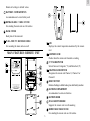
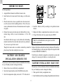
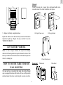
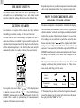
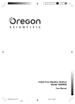
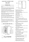
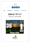
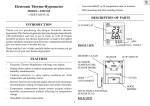
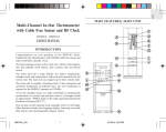
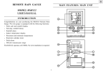
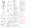
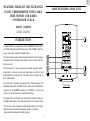
GB
WEATHER FORECAST MULTI-CHANNEL
IN-OUT THERMOMETER WITH CABLE
FREE SENSOR AND RADIO
CONTROLLED CLOCK
MAIN FEATURES: MAIN UNIT
MODEL: BAR888A
USER’S MANUAL
INTRODUCTION
Congratulations on your purchase of the BAR888A Weather Forecast Multi-Channel In-Out Thermometer with 433MHz cable free
sensor and radio-controlled calendar clock.
The basic package comes with a main unit (which is the barometer,
temperature and calendar clock station), and a remote unit (the
thermo sensor).
The main unit has large read-outs for weather forecast, indoor
temperature, calendar clock and temperatures collected and
transmitted by the remote unit. The main unit can support up to
three remote units.
The main unit is capable of keeping track of the maximum and
minimum temperature of different sites. And no wire installation is
required. As the BAR888A operates at 433MHz, it can be used
in the U.S. and most places in Continental Europe.
FRONT VIEW
It automatically synchronizes its current time and date when it is
brought within range of the radio signal from U.S. Atomic Clock.
You can also set the calendar clock manually when it is off range.
Other features include three-language display, crescendo
alarm and interchangeable display modes.
1
GB
FIVE-LINE DISPLAY
Facilitates easy reading of weather forecast, remote and indoors
temperatures and calendar clock
CHANNEL BUTTON
Selects among different channels
MEMORY BUTTON
Recalls the maximum or minimum temperature of individual
channels
ALARM (
) ON/OFF BUTTON
Enables or disables the alarm
ALARM/ 24hr
OFF BUTTON
BACK VIEW
Sets the time for the alarms
( WITHOUT BACK COVER )
MODE/SET BUTTON
Toggles the display modes and confirms entry while setting
the values for display
RADIO RECEPTION SIGNAL
Indicates the condition of radio reception
°C/°F SLIDE SWITCH
Selects between degree Centigrade (°C) and Fahrenheit (°F)
( + ) BUTTON
Advances the value of a setting
RESET BUTTON
BACK VIEW
( WITH BACK COVER )
2
GB
Returns all settings to default values
BATTERY COMPARTMENTS
Accommodates an AA-size battery each
RETRACKABLE TABLE STAND
For standing the main unit on a flat surface
BACK COVER
Back plate of the main unit
WALL-MOUNT RECESSED HOLE
LCD
Displays the current temperature monitored by the remote
unit
For mounting the main unit on a wall
MAIN FEATURES: REMOTE UNIT
LED INDICATOR
Flashes when the remote unit transmits a reading
°C/°F SLIDE SWITCH
Selects between Centigrade (°C) and Fahrenheit (°F)
CHANNEL SLIDE SWITCH
Designates the remote unit Channel 1, Channel 2 or
Channel 3
RESET BUTTON
Returns all settings to default values; press after battery insertion
BATTERYCOMPARTMENT
Accommodates two AA-size batteries
BATTERY DOOR
WALL-MOUNT HOLDER
Supports the remote unit in wall-mounting
REMOVABLE TABLE STAND
For standing the remote unit on a flat surface
3
GB
BEFORE YOU BEGIN
For best operation,
1. Assign different channels to different remote units.
2. Insert batteries for remote units before doing so for the main
unit.
3. Place the main unit as close as possible next to the remote unit,
reset the main unit after installing batteries. This will ensure
easier synchronization between the transmission and reception
of signals.
4. Insert the batteries strictly according to the polarities shown
therein.
5. Replace the battery compartment door and secure its screws.
4. Position the remote unit and main unit within effective transmission range, which, in usual circumstances, is 90 to 100
feet.
6. Using a blunt styles such as a paper clip, press RESET.
Note that the effective range is vastly affected by the building
materials and where the main and remote units are positioned.
Try various set-ups for best result.
Note: To avoid malfunction, alway press reset after
battery replacement.
Though the remote units are weather resistant they should be
placed away from direct sunlight, rain or snow.
Replace the batteries when the low-battery indicator of the particular channel lights up on the main unit. (Repeat the steps described
in section “BEFORE YOU BEGIN”)
Note that once a channel is assigned to a remote unit, you can only
change it by removing the batteries or resetting the unit.
BATTERY AND CHANNEL
INSTALLATION: REMOTE UNIT
The unit uses 2 AA-size batteries which are installed in the factory
for you. Should you need to change the battery,
BATTERY INSTALLATION: MAIN UNIT
The unit uses 4 AA-size batteries which are installed in the factory
for you. Should you need to change the battery,
1. Remove the screws on the battery compartment.
2. Select the channel number on the CHANNEL slide switch.
1. Slide open the battery compartment door.
3. Select the temperature display unit on the °C/°F slide switch.
2. Insert the batteries strictly according to the polarities shown therein.
4
GB
Main unit
As for the remote unit, it comes with a wall-mount holder and a
removable stand. Use either to hold the unit in place.
1. Lift up the back cover
3. Replace the battery compartment door.
2.Flip up the stand
Replace the batteries when the low-battery indicator of the indoors
temperature lights up. (Repeat the steps described in section
“BEFORE YOU BEGIN”)
LOW BATTERY WARNING
When it is time to replace batteries, the respective low-battery
indicator will show up when the respective channel is selected. The
battery level of the main unit will be shown on the indoor temperature
when it is running low.
3. Close the back cover
Remote unit
HOW TO USE THE TABLE STAND OR
WALL MOUNTING
The main unit has a retractable table stand, which when flipped
open, can support the unit on a flat surface. Or you can flip close the
stand and mount the unit on a wall using the recessed screw hole.
5
Wall-mount
Table Stand
GB
Repeat this step whenever you find discrepancies between the reading
shown on the main unit and that on the respective remote unit.
THE RESET BUTTON
This button is only used when the unit is operating in an
unfavorable way or malfunctioning. Use a blunt stylus to hold
down the button. All settings will return to their default values.
HOW TO CHECK REMOTE AND
INDOORS TEMPERATURES
GETTING STARTED
The indoors temperature is shown on the 3rd line of the display.
Once batteries are in place for the remote units, they will start
transmitting temperature readings at 30-second intervals.
As for the remote sites or channels, press CHANNEL to go from one
channel to another. The kinetic wave display on the channel number
indicates the reception of that particular channel is in good order.
The main unit will also start searching for signals for about a
minute once batteries are installed. Upon successful reception, the
individual channel temperatures will be displayed on the 2nd line
and the indoors temperature on the 3rd line. The main unit will
automatically update its readings at about 30-second intervals.
If no readings are received from one particular channel for more
than two minutes, blanks “
” will be displayed until further
readings are successfully searched. Check the remote unit is sound
and secure. You can wait for a little while or press CHANNEL and
MEMORY simultaneously to enforce an immediate search. Of course
no reading will be shown if no remote unit is assigned to that
channel.
The temperature trend indicator on the screen shows the trend of
samplings collected at that particular remote site. Three trends,
rising, steady and falling, will be shown.
Arrow
indicator
Temperature
Trend
If no signals are received, blanks “
” will be displayed and
the kinetic wave icon will show “
”. Press CHANNEL and
MEMORY simultaneously to enforce another search for about 30
seconds. This is useful in synchronizing the transmission and
reception of the remote and main units.
Rising
Steady
Falling
If the temperature goes above or below the temperature measuring
range of the main unit or the remote unit (stated in specification) ,
the display will show “HHH” or “LLL”.
6
GB
HOW TO READ THE KINETIC
WAVE DISPLAY
DISCONNECTED SIGNALS
If without obvious reasons the display for a particular channel
goes blank, press CHANNEL and MEMORY to enforce an
immediate search. If that fails, check:
The kinetic wave display shows the signal receiving status of the
main unit. There are three possible forms:
1. The remote unit of that channel is still in place.
2. The batteries of both the remote unit and main unit. Replace as
necessary.
The unit is in searching mode.
Temperature readings are securely
registered.
Note: When the temperature falls below freezing point, the
batteries of outdoor units will freeze, lowering their voltage
supply and the effective range.
No signals.
3. The transmission is within range and path is clear of obstacles
and interference. Shorten the distance when necessary.
MAXIMUM AND MINIMUM
TEMPERATURES
TRANSMISSION COLLISION
Signals from other household devices, such as door bells, home
security systems and entry controls, may interfere with those of
this product and cause temporarily reception failure. This is normal
and does not affect the general performance of the product. The
transmission and reception of temperature readings will resume
once the interference recedes.
The maximum and minimum recorded indoor temperatures and
those of each channel will be automatically stored in memory. To
display them,
1. Select the channel to be checked.
2. Press MEMORY once to display the maximum temperature and
again the minimum temperature. The respective indicators,
MAX or MIN will be displayed.
NOTE ON °C AND °F
To clear the memory, hold down MEMORY for two seconds. The
maximum and minimum temperatures will be erased. If you press
MEMORY now, the maximum and minimum temperatures will
have the same values as the current ones until different readings are
recorded.
The unit of temperature display is selected on the °C/°F slide
switch. Select °C for Centigrade or °F for Fahrenheit.
Note: The remote temperature display shown on the main unit is
dominated by the selection on the °C/°F slide switch of the main
unit. Whatever the display units of the remote sensors are, they will
be automatically converted to the chosen one of the main unit.
7
GB
WEATHER FORECAST FUNCTION
HOW TO READ THE PRESSURE TREND
Your BAR888A detects barometric pressure changes and the LCD
displays the illustrated weather symbols which indicates the
weather forecast for 12 to 24 hours ahead, for an area with a radius
of about 30-50 km.
The BAR888A gives you the pressure trend for the last hour. It is
indicated by the arrow displayed in the right hand side of the upper
display. An upward pointing trend arrow indicates that it is likely
that the weather is improving or may be getting worse if the trend
(arrow) is falling. Here is what it can look like:
Indicator
displays on
the unit
Forecast
Arrow
indicator
Sunny
Slightly Cloudy
Cloudy
Rainy
Pressure
Trend
Important:
1. The accuracy of weather forecasting when using pressure
trend alone is about 70 to 75 percent and, therefore, the
manfuacturers and suppliers cannot be held responsible for
any inconveniences caused by an inaccurate weather fore
cast.
Rising
Steady
Falling
CALENDAR CLOCK DISPLAY MODES
The BAR888 supports two display modes in the sequence of:
MODE 1. Hour-Minute-Second (of local time)
2. The weather forecast symbols may not reflect current weather
condition. The symbols are forecasting the future.
Day-Month (of local time)
3. A “SUNNY” forecast covering the night-time reflects fine clear
weather.
MODE 2. Hour-Minute-Day of the Week (of local time)
Day-Month (of local time)
8
GB
When the reception is complete, the radio reception signal will
stop blinking. The strength of the reception for the last full hour
will be indicated.
-Strong
-Weak
- No singal
-Receiving
ABOUT RADIO RECEPTION
For better reception, place the clock away from metal objects and
electrical appliances to minimize interference.
The BAR888A is designed to automatically synchronize its current
time and date when it is brought within range of the radio signal
from U.S. Atomic Clock.
button for three seconds. The radio reception signal will disappear.
The unit will not respond to radio signals.
If you wish to disable the auto-reception feature, press zone
When the BAR888 is within range, its radio-control mechanism
will override all manual settings.
To enable the feature again, press the (+ ) button for three
seconds. The radio reception signal will start blinking to initiate
reception automatically.
When the unit is receiving radio signal, the radio reception signal
will start to blink. A complete reception generally takes about 2 to
10 minutes, depending on the strength of the radio signal.
9
GB
HOW TO SET THE CLOCK MANUALLY
To set the clock manually, hold MODE/SET for three seconds. The
display will return to MODE 1, with the hour digits blinking.
2. Press 24hr
blink.
Use ( + ) to select the hour. Press and hold to increase
the value rapidly.
3. Enter the hour using ( + ).
Press MODE/SET to confirm. The minute digits will blink. Repeat
the same procedure to set the minutes, then the day-of-month,
month, display language, day-of-week and offset for the second
time zone.
4. Press 24hr
OFF. The minute digits will blink.
5. Enter the minutes using (+ )
Note: The time and date are displayed in 12-hour clock and DAYMONTH format. For the language display, you can choose among
English (E), German (D), French (F) and Italian (I). Day-of-week is
the usual sequence of Monday through Sunday.
6. Press 24hr
OFF to exit.
You can also arm or disarm an alarm by pressing the
For the second time zone, which is indicated by the ZONE ICON,
enter the hour offset using the UP and DOWN buttons and the
BAR888 will calculate the second time accordingly.
button.
When an alarm is armed, it will go off at the set time.
If there is an item you do not wish to change, simply press MODE/
SET to bypass the item.
When you are done, press MODE/SET to exit. The display will
return to the mode last chosen.
HOW TO SET AND ARM THE ALARM
To set an alarm,
1. Press 24hr
OFF for three seconds. 12:00 AM will
OFF once to display the alarm time
10
ON/OFF
GB
HOW TO STOP AN ALARM
To stop an alarm, you can use either 24hr
OFF or
TIME ZONE AND OFFSET TABLE
ON/OFF.
OFF will stop the alarm, which is still armed and
Pressing 24hr
will go off at the set time the following day.
If
ON/OFF is pressed instead, the alarm will be stopped and
deactivated all together
PRECAUTIONS
This product is engineered to give you years of satisfactory service
if you handle it carefully. Here are a few precautions:
1. Do not immerse the unit in water.
2. Do not clean the unit with abrasive or corrosive materials. They
may scratch the plastic parts and corrode the electronic circuit.
3. Do not subject the unit to excessive force, shock, dust, temperature or humidity, which may result in malfunction, shorter
electronic life span, damaged battery and distorted parts.
SPECIFICATIONS
4. Do not tamper with the unit’s internal components. Doing so
will invalidate the warranty on the unit and may cause
unnecessary damage. The unit contains no user-serviceable
parts.
Temperature Measurement
Main unit
Indoor Temperature measurement
5. Only use fresh batteries as specified in the user’s manual. Do
not mix new and old batteries as the old ones may leak.
Displayed IN temperature range
6. Always read the user’s manual thoroughly before operating the
unit.
Proposed operating range
Temperature resolution
11
: -9.9°C to +70.0°C
(14.2°F to 158.0°F)
: -5.0°C to +50.0°C
(23.0°F to 122.0°F)
: 0.1°C (0.2°F)
GB
Day of week selectable in 4 language (E,F,S)
Remote Temperature measurement
Displayed OUT temperature range : -50.0°C to +70.0°C
(-58.0°F to 158.0°F)
Proposed operating range
: -5.0°C to +50.0°C
(23.0°F to 122.0°F)
Temperature resolution
: 0.1°C (0.2°F)
2-minute crescendo alarm
Power
Main unit
Remote sensing unit
Remote unit
Displayed range
: -50.0°C to +70.0°C
(-58.0°F to 158.0°F)
Proposed operating range
: -20.0°C to +60.0°C
(-4.0°F to 140.0°F)
Temperature resolution
: 0.1°C (0.2°F)
RF Transmission Frequency
: 433 MHz
No. of Remote unit
: Maximum of 3
RF Transmission Range
: Maximum 30 feet
Temperature sensing cycle
: around 30 seconds
(100 meters)
: use 4 pcs UM-3 or “AA”
1.5V alkaline battery
: use 2 pcs UM-3 or “AAA
1.5V alkaline battery
Weight
Main unit
Remote sensing unit
: 306gm (10.79 ounces)
: 100 gm (3.53 ounces)
Dimension
Main unit
Remote sensing unit
: 182 x 133 x 28 mm
(7.17x5.24x1.10 inches)
: 92 x 60 x 21 mm
(3.62x2.36x0.83inches)
NOTE ON COMPLIANCE
Barometric Pressure Measurement
Pressure measuring range
: 795 to 1050 mb/ hPa
(23.48 to 31.01 inHg)
This product complies to standards and specifications of BZT, FCC
and article number 334 of PTT.
Pressure sampling cycle
: 15 minutes
Warning: Changes or modifications to this unit not expressly
approved by the party responsible for compliance could void the
user’s authority to operate the equipment.
Radio Controlled Clock
Maintime set and synchronized by Radio Signal from U.S.
Atomic Clock
NOTE: This equipment has been tested and found to comply with
the limits for a Class B digital device, pursuant to Part 15 of the
FCC Rules. These limits are designed to provide reasonable
protection against harmful interference in a residential
12 h display with hh:: mm: ss
12
GB
installation. This equipment generates, uses and can radiate radio
frequency energy and, if not installed and used in accordance with
the instructions, may cause harmful interference to radio
communications.
CAUTION
— The content of this manual is subject to change without
further notice.
However, there is no guarantee that interference will not occur in a
particular installation. If this equipment does cause harmful interference to radio or television reception, which can be determined
by turning the equipment off and on, the user is encouraged to try
to correct the interference by one or more of the following measures:
— Due to printing limitation, the displays shown in this
manual may differ from the actual display.
— The contents of this manual may not be reproduced
without the permission of the manufacturer.
o Reorient or relocate the receiving antenna.
o Increase the separation between the equipment and receiver.
o Connect the equipment into an outlet on a circuit different from
that to which the receiver is needed.
o Consult the dealer of an experienced radio/TV technician for
help.
Company Name: Oregon Scientific, Inc.
Address: 19861 SW 95th Avenue, Tualatin, Oregon 97062, USA
CUSTOMER ASSISTANCE
Should you require assistance regarding this product and its
operation, please contact our customer care department at
1-800-853-8883 or via email at [email protected].
13