1
INTRUSION AND FIRE ALARM PANEL
SIGNAL-20M
User’s Manual
TABLE OF CONTENTS
1
General ..................................................................................................................................................3
2
Specifications ........................................................................................................................................4
3
Standard Delivery ..................................................................................................................................6
4
Description and Performance ................................................................................................................6
4.1
4.2
4.3
4.4
5
Utilization ............................................................................................................................................25
5.1
5.2
5.3
5.4
5.5
5.6
5.7
5.8
6
Alarm Loops .................................................................................................................................................................. 6
Relays........................................................................................................................................................................... 16
Device Parameters ....................................................................................................................................................... 20
Operation Modes.......................................................................................................................................................... 22
Preparation for Using ................................................................................................................................................... 25
Fire Alarms .................................................................................................................................................................. 27
Intrusion Alarms .......................................................................................................................................................... 28
Auxiliary Alarms .......................................................................................................................................................... 31
Arming and Disarming Alarm Loops ........................................................................................................................... 33
Operator Mode ............................................................................................................................................................. 33
Administrator Mode ..................................................................................................................................................... 34
Maintenance ................................................................................................................................................................. 35
Manufacturer’s Data ............................................................................................................................36
APPENDIX A ............................................................................................................................................37
APPENDIX B ............................................................................................................................................38
APPENDIX C ............................................................................................................................................39
APPENDIX D ............................................................................................................................................40
APPENDIX E ............................................................................................................................................41
WARNING
To edit configuration parameters of the device, please use
UPROG.EXE Configuration Tool of version 4.1.0.26 or higher.
1
General
1.1 Signal-20M Fire Alarm and Intrusion Panel (herein after referred to as the panel) is
designed to:
− Monitor for 20 zones of an intrusion alarm system, fire alarm system, or panic alarm system;
− Receive messages from fire and intrusion detectors, call points and panic alarms; passive,
active (powered via the alarm loops), or four-wire detectors with normally closed or normally open
internal contacts;
− Control light and sound alarms;
− Receive commands and to send messages over the RS-485 interface to the network controller
(either an S2000M console or a PC with Orion Pro Software installed);
− Send fire alarms and troubles to a fire brigade;
− Send alarms to a central monitoring station.
3
The panel provides:
− Arming and disarming individual alarm loops manually or by a network controller command;
− Arming and disarming arbitrary groups of alarm loops which are combined by a single User
password;
− Typing a PIN code which is a User password;
− Remote or local control of output relays;
− Monitoring circuits of connecting light or/and sound alarms (outputs K4 and K5) for open and
short circuit failures;
− Connecting a backup input of electric power to an extra input.
The panel can operate standalone or used as an addressable device in case of cooperating with a
network controller within an Orion system.
1.2 The panel can be used for independent or centralized protection of building or premises
(rooms, stores, banks, warehouses, apartments, residential houses, enterprises) against unauthorized
access and fires.
1.3 The panel is to be powered from one or two power supplies (main and backup ones) of 10.2
V dc to 28.0 V dc. Bolid manufactured battery backed power supplies RIP-12 or RIP-24 are
recommended.
1.4 The panel is intended for round–the-clock operation and is to be attached within closed
non-heated spaces.
1.5 The panel should not be used within aggressive and dusty mediums as well as in explosionhazardous premises. The ingress protection rating is IP20.
1.6 The panel can be operated in the following ambient conditions:
1) Operating Temperatures minus 30°C to +55°C;
2) Relative humidity 98% at +25°C;
3) Vibration loads 1 Hz to 35 Hz at maximum acceleration of 4.9 m/s2 (0.5 g).
1.7 Mean time between failures at least 20,000 hours.
1.8 False alarms 0.01 per 1000 hours max.
1.9 The average lifespan of the panel is estimated as 10 years.
1.10 The weight of the panel doesn’t exceed 0.5 kg.
1.11 The overall dimensions are 247 mm x 150 mm x 48 mm max.
1.12 The pre-operation time after powering up doesn’t exceed 3 s provided that there is stable
voltage higher than 11 V at the panel’s power terminals.
2
2.1
2.2
2.3
Specifications
The number of alarm loops (initiating device circuits) is 20.
The branching index (the number of commuted circuits) is five.
The number of inputs for monitored circuits is 25:
− Circuits of alarm loops 1 to 20;
− Monitored circuits of outputs "Relay 4" and "Relay 5";
− Power supply inputs of the panel,
− RS-485 interface ("A", "B").
2.4 The number of executive relay outputs is five including;
− Three relay switch outputs of dry contact type: with the maximum voltage up to 28 V and
the current up to 2 A or up to 80 V and current 0.1 mA to 50 mA (outputs "Relay 1", "Relay 2",
"Relay 3");
− Two outputs with monitoring alarm connection circuits: with maximum voltage up to
28 V and with the current up to 0.8 A (outputs "Relay 4", "Relay 5");
2.5 Information capacity of the panel (the number of types of the events) exceeds 25.
2.6 The panel transmits alarms to the network controller over the highway interface RS-485.
Communication parameters:
− Baud rate: 9600 bps;
− Type of communication: half0duplex.
If a PC operates as the network controller then data are communicated via a Bolid manufactured
interface converter such as USB-RS485, S2000-PI, or S2000-USB.
4
2.6.1 If at the moment of generating a message the panel couldn’t communicate with the network
controller, the event is stored into the non-volatile memory of the panel and, when the communication
over the RS-485 interface is restored, the event is transmitted to the network controller along with the
time and date of its origin.
The capacity of the event buffer in the non-volatile memory is 511 events.
2.7 If the power supply voltage has dropped to 10 V, the panel enters the Power Failure mode.
As soon as the power supply voltage rises up to 11 V and above, the panel returns to the quiescent mode.
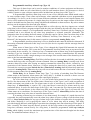
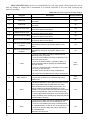
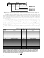
2.8 The typical valuations of current consumed by the panel in main operation modes in case of
normal operation are demonstrated in Table 2.1.
Table 2.1. Standard Values of the Consumed Current
Panel Condition
State
All the alarm loops are armed and all the detectors
are contacting (no detectors powered via the
alarm loops)
All the alarm loops are armed; all the detectors
consume current (are powered via the alarm
loops), the current consumed by the detectors in
each alarm loop is 3 mA (60 mA in total)
Norm
Supply Voltage
12 V
24 V
400 mA
200 mA
Intrusion Alarm
400 mA
200 mA
Norm
600 mA
300 mA
Fire Alarm
650 mA
330 mA
If the alarm loops of the panel are loaded not in full (there are current-consuming detectors but
their total consumed current is less than the maximum value), then the current consumed by the panel
can be considered to rise in direct ration with increasing of the current consumed by the detectors.
Hence, the current consumed by the panel can be estimated using the following formulas:
1. In case of powering from a 12 V power supply:
I = 3,33 ⋅ i + 400 [mA].
2. In case of powering from a 24 V power supply:
I = 1,67 ⋅ i + 200 [mA],
Where: I stands for the total current consumed by the panel (without regards to external
alarms) [mA],
i stands for the current consumed by the active detectors in the alarm loops of the
panel [mA].
The total time of backup operation is estimated by the formula:
T = 1000 ⋅ W / I [h],
Where: W stands for the capacity of the battery [A⋅h],
I stands for the panel consumed current [mA].
2.9 The panel in the quiescent mode provides the alarm loop inputs with the steady voltage
19 V to 22 V provided that the termination resistance is 4.7 K and the detectors consume less than 3 mA.
2.10 In case of a short circuit failure of an alarm loop the panel provides other alarm loop inputs
with steady voltage in accordance with Clause 2.9.
2.11 The panel limits the current of the alarm loop with the short circuit failure at the level no
more than 26.5 mA.
2.12 The effective value of the ripple voltage within an alarm loop doesn’t exceed 20 mV.
2.13 If intrusion alarm detectors are included into an alarm loop (an intrusion alarm loop), the
panel is in the quiescent mode with the following parameters:
− Maximum wire resistance without regard to the termination resistor is 1 K;
− Minimum leakage resistance between loop wires or between each wire and the earth is 20 K.
If fire alarm detectors are included into an alarm loop (a fire alarm loop), the panel is in the
quiescent mode with the following parameters:
− Maximum wire resistance without regard to the termination resistor is 100 ohms;
− Minimum leakage resistance between loop wires or between each wire and the earth is 50 K.
2.14 The panel is resistant to the effects of electromagnetic interference within alarm loops in
form of sine voltage influences of 50 Hz frequency and an effective value of the voltage 1 V, as well as
5
to pulse interferences in form of single voltage pulses with amplitudes up to 300 V and duration up to 10
ms.
3
Standard Delivery
Find the following unpacking the Signal-20M panel:
1) Signal-20M Intrusion and Fire Alarm Panel
2) Instruction Manual
3) Component Parts:
− 0.5 W – 4.7 kOhm (MF 1/2W-4K7±5%) Resistor
− 1N5400 (1N5401 - 1N5406) Diode
− 1N4148 Diode
− Woodscrew
− Wall Plug 6x30
4) Lined Sticky Sheet
4
– 1 pc.;
– 1 pc.;
– 20 pcs.;
– 2 pcs.;
– 2 pcs.;
– 3 pcs.;
– 3 pcs.;
– 2 pcs.
Description and Performance
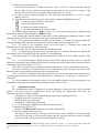
The view of the panel along with its overall and mounting dimensions are shown in Appendix A.
The panel enclosure consists of the cover (1) and the base (2). There are buttons (keys) of the
panel alarm loops 1 to 20 and control keys
,
,
,
on the panel’s cover.
The cover also houses the indicators (LEDs) of the alarm loops, the indicators of output’s
conditions and function indicators READY, FIRE, ALARM, and FAULT.
On the panel’s base a PCB with radio elements, push-button micro switches, light emitted diodes,
terminals for external connections, and a tamper switch is attached. Also the panel’s base comprise two
drawers (3) for sticking labels with user’s remarks (for example, "Alarm loops 1 to 8: the ground floor,
intrusion alarms", "Alarm loops 9 to 15: the first floor, intrusion alarms", "Alarm loops 16 to 18: fire
alarms, the ground floor and the first floor", "Alarm loops 19 to 20: the entrance doors").
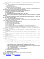
The structural diagram of the panel is shown in Appendix B.
The panel consists of the following main elements:
− Push-button micro switches;
− Channel commutator;
− Voltage converter to power the alarm loops;
− Processors;
− Light indicators;
− Relays;
− Alarm loop power reset device;
− RS-485 interface converter;
− Non-volatile memory;
− Tamper switch.
Voltage from measuring circuits of the alarm loops arrives to the input of the channel
commutator. The processor, which operates the commutator, one-by-one connects the input of the builtin ADC to the alarm loops. In this process the resistance of the alarm loops is estimated and the states of
the alarm loops are defined.
The voltage converter generates stabilized voltage to supply power to the alarm loops and the
processor.
The processor controls the overall operation of the panel:
– Cyclically polls the alarm loops and monitors their conditions by measuring their resistance;
– Operates the internal light indicators and relays, resets the power of the alarm loops;
– Receives commands and send messages over the RS-485 interface.
For adapting with the line of two-wire interface RS-485 the panel uses the interface converter.
The non-volatile memory is used to store the buffer of events along with the dates of their
appearance.
DIS
4.1
Alarm Loops
The panel monitors twenty alarm loops and, depending on their conditions:
6
− Indicates the states of each alarm loop by built-in two-color LEDs "1" to "20";
− Indicates the current state of the panel itself by built-in LEDs ALARM, FIRE, FAULT;
− Activates the built-in panel sounder in cases of breaking alarm loops;
− Controls five relays of the panel.
The status of an alarm loop is defined by its type, the current resistance, and the current logic
state (armed or disarmed).
4.1.1 Any fire and intrusion detectors designed to be powered by a DC supply can be brought
into the alarm loops of the panel, however the internal resistance of each detector in the Fire Alarm
status should be:
− No more than 2.7 K for normally open detectors;
− No less than 3.2 K for normally closed detectors.
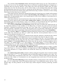
4.1.2 Configuration Parameters of the Alarm Loops.
Configuration parameters of the alarm loop shown below in Table 4.1 provide changing
monitoring algorithms of the alarm loops.
Parameter
Loop Type
Alarm Delay
Arming Delay
Loop Analysis Delay
Relay 1 Activation
Delay
Relay 2 Activation
Delay
Relay 3 Activation
Delay
Relay 4 Activation
Delay
Relay 5 Activation
Delay
Never Disarmed
Table 4.1. Configuration Parameters (Attributes) of the Alarm Loops
Description
Range
1 – Smoke Fire
2 – Combined Fire
3 – Heat Fire
4 – Intrusion
Defines the tactics of monitoring the alarm loop, 5 – Intrusion with Tamper
the kinds of detectors to be brought into the
Monitoring
alarm loop, and a set of states of the alarm loop 6 – Auxiliary
7 – Entrance
11 – Panic
12 – Auxiliary
Programmable
0 to 254 s,
The delay for switching from the Entrance
255 means OFF
Alarm status to the Intrusion Alarm status, or
(do not switch to a Fire
from the Fire Pre-Alarm status to the Fire Alarm Alarm status on receiving a
status
response from a single
detector)
The pause between a command to arm the alarm
loop and switching the alarm loop to the Armed
0 to 255 s
state
The time required to complete transient
processes in alarm loops in case of restoring
1 s to 32 s
power after a power reset. Within this time the
status of each alarm loop is not analyzed
A delay (in seconds) between changing an alarm
loop status and activation of the relay
0 to 255 s
The alarm loop cannot be disarmed in any way
On / Off
7
Parameter
Auto Rearming After
Failing
Auto Arming After
Alarm
Disarmed Loop
Monitoring
Fire Loop Requery
Prohibition
300-ms Integration
Time
10 % Deviation
Blocking
Description
Automatic switch from the Arming Failed mode
to the Armed mode in case of recovering the
alarm loop
Automatic switch from the Intrusion Alarm
mode, Panic Alarm mode, or Fire Alarm mode
in case of recovering the alarm loop
Provides transmitting messages about changing
of a disarmed alarm loop status (normal or not)
over the RS-485 interface
Being set on, disables the function of querying
the loop of the types 1 and 2 repeatedly
Being set on, causes the intrusion alarm loop to
enter the Intrusion Alarm status if the loop has
been activated for more than 300 ms
Being set on, causes the intrusion alarm loop not
to enter to the Intrusion Alarm status if its
resistance value has been changed more than by
10 % within 255 s
Range
On / Off
On / Off
On / Off
On / Off
On / Off
On / Off
Relay 1 Control
On / Off
Relay 2 Control
On / Off
Assign activation of the relay with this alarm
Relay 3 Control
On / Off
loop
Relay 4 Control
On / Off
Relay 5 Control
On / Off
The main alarm loop configuration parameter which defines the way of monitoring the alarm
loop and the type of initiating devices which can be brought into the alarm loop is the Loop Type.
Signal-20M supports 9 different types of alarm loops.
Type 1 – Smoke Two Threshold Alarm Loop
A loop of the Type 1 (Smoke Two Threshold) is intended to involve fire smoke (normally open)
detectors. This loop is considered to be in one of the following statuses:
Armed
The alarm loop is monitored, its resistance being normal
Disarmed
The alarm loop is not monitored
Arming Delay
The Arming Delay has not yet expired
Fire Prealarm
A single detector has actuated within the alarm loop
Fire Alarm
At least two detectors in the alarm loop have actuated, or Alarm Delay
has expired after a single detector actuation
Short Circuit Failure
The resistance of the alarm loop is less than 100 Ω
Open Circuit Failure
The resistance of the alarm loop is more than 6 kΩ
Arming Failed
The alarm loop has been open at the moment of being armed
As soon as a detector included in the alarm loop have actuated, the Signal-20M generates a FIRE
SIGNAL message and repeatedly queries the condition of the alarm loop by doing the following. The
panel unsets loop power for 3 s. If within 55 s after power reset the detector actuates repeatedly, then the
alarm loop is considered to be in the Fire Prealarm status. Otherwise, if the detector has not actuated
repeatedly within 55 s, the alarm loop is considered to be in Armed status. The alarm loop can switch
from the Fire Prealarm status to the Fire Alarm status if a second detector included into this alarm loop
has actuated, as well as if the given Alarm Delay has expired. (If Alarm Delay is set with zero value,
Fire Prealarm status will switch to Fire Alarm status immediately.) The Alarm Delay value of 255 s (the
maximum possible value) corresponds to unlimited timeout, and switching from the Fire Prealarm status
8
to the Fire Alarm status is implemented only after actuating of another detector included into the alarm
loop.
The integration time for an alarm loop of the Type 1 is defined in accordance with the
requirements of Clause 4.1.3.
Table 4.2 shows the match between current resistance values and corresponding states of alarm
loops of the Type 1.
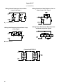
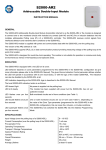
The wiring diagram for including fire smoke (normally open) detectors into alarm loops of the
Type 1 is presented in Appendix E.
Combined Fire Single Threshold Alarm Loop (Type 2)
A loop of the Type 2 (Combined Fire Single Threshold) is intended to involve fire smoke
(normally open) and heat (normally closed) detectors. This loop is considered to be in one of the
following statuses:
Armed
The alarm loop is monitored, its resistance being normal
Disarmed
The alarm loop is not monitored
Arming Delay
The programmed Arming Delay has not been expired
Fire Prealarm
Either activation of a heat detector or repeated activation of a smoke
detector is recognized within the loop
Fire Alarm
The Alarm Delay has expired after actuation of single detector
Short Circuit Failure
The resistance of the loop is less than 100 Ω
Open Circuit Failure
The resistance of the loop is more than 16 KΩ
Arming Failed
An attempt to arm the loop has failed because the loop is activated
A heat detector having actuated, the loop switches to the Fire Prealarm status.
When a smoke detector has actuated, the Signal-20M generates a FIRE SIGNAL message and
repeatedly queries condition of the loop (see above the Type 1). If detector actuation is confirmed, the
loop switches to the Fire Prealarm status.
The loop can switch from the Fire Prealarm status to the Fire Alarm status after expiring of the
set Alarm Delay. If the value of the Alarm Delay equals to zero, then the loop will switch from the Fire
Prealarm status to the Fire Alarm status immediately. The Alarm Delay value of 255 s (maximum
possible value) means unlimited time delay, so the loop never switches from the Fire Prealarm status to
the Fire Alarm status.
The integration time for an alarm loop of the Type 2 is defined in accordance with the
requirements mentioned in Clause 4.1.3.
Table 4.2 shows the match between current resistance values and corresponding statuses of alarm
loops of the Type 2.
The wiring diagram for including fire smoke (normally open) and fire heat (normally closed)
detectors into alarm loops of the Type 2 is presented in Appendix E.
Heat Two Threshold Alarm Loop (Type 3)
A loop of the Type 3 (Heat Two Threshold) is intended to involve fire heat (normally closed)
detectors.
This loop is considered to be in one of the following states:
Armed
The alarm loop is monitored, its resistance being normal
Disarmed
The alarm loop is not monitored
Arming Delay
The programmed Arming Delay has not been expired
Fire Prealarm
A single detector has actuated within the alarm loop
Fire Alarm
At least two detectors brought in the alarm loop have actuated, or the
Alarm Delay has expired after actuation of a single detector
Short Circuit Failure
The resistance of the loop is less than 2 K
9
Open Circuit Failure
The resistance of the loop is more than 25 KΩ
Arming Failed
An attempt to arm the loop has failed because the loop is activated
An included detector having actuated, the loop switches to the Fire Prealarm status. The loop can
switch from the Fire Prealarm status to the Fire Alarm status if a second detector in the loop has
actuated, or the programmed Alarm Delay has expired. If the Alarm Delay is equal to zero, then the
loop switches from the Fire Prealarm status to the Fire Alarm status immediately. The Alarm Delay
value of 255 s (maximum possible value) is considered as infinite time delay, when switching from the
Fire Prealarm status to the Fire Alarm status can be implemented only after actuation of a second
detector within this alarm loop.
The integration time for an alarm loop of the Type 3 is defined in accordance with the
requirements mentioned in Clause 4.1.3.
Table 4.2 shows how current resistance values of alarm loops of the Type 3 matches with its
corresponding states.
The wiring diagram for including fire heat (normally closed) detectors into alarm loops of the
Type 3 is presented in Appendix E.
Intrusion Alarm Loop (Type 4)
A loop of the Type 4 (Intrusion) is intended to involve any intrusion detectors, both normally
open and normally closed, and powered either over the loop or separately.
This loop is considered to be in one of the following states:
Armed
The alarm loop is monitored, its resistance being normal
Disarmed
The alarm loop is not monitored
Arming Delay
The programmed Arming Delay has not yet expired
Intrusion Alarm
The alarm loop has been activated
Arming Failed
An attempt to arm the loop has failed because the loop is activated
An Intrusion alarm loop is considered to be activated if its resistance goes out of normal range as
well as if it jumps by more than 10 % (provided that the 10% Deviation Blocking parameter is set off).
Activating an intrusion alarm loop causes it to enter the Intrusion Alarm status.
An alarm integration time for this type of alarm loops can be 70 ms or 300 ms depending on the
programmed value of the 300-ms Integration Time parameter.
Table 4.2 shows how the alarm loop resistances match with the states of an alarm loop of the
Type 4.
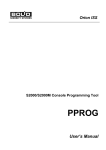
The wiring diagram for including intrusion detectors into alarm loops of the Type 4 is presented
in Appendix E.
Intrusion Alarm Loop with Tamper Monitoring (Type 5)
A loop of the Type 5 (Intrusion with Tamper Monitoring) is intended to involve a single intrusion
detector and the tamper switch of this detector.
This loop is considered to be in one of the following states:
Armed
The alarm loop is monitored, its resistance being normal
10
Disarmed
The alarm loop is not monitored
Arming Delay
The programmed Arming Delay has not yet expired
Intrusion Alarm
The alarm loop has been activated
Arming Failed
An attempt to arm the loop has failed because the loop is activated
Tamper Alarm
The case of the disarmed detector has been tampered
Tamper Restored
The tamper of the disarmed detector has been restored
When the alarm loop is armed, either any skip of the resistance value (by more than 10%) or
actuation of the detector (opening of its alarm contact), or tamper switch actuation causes the loop to be
considered as being in the Intrusion Alarm status. When the alarm loop is disarmed, either tamper switch
actuation or loop short circuit failure causes the alarm loop to be considered as being in the Tamper
Alarm status.
An alarm integration time for this type of alarm loops can be 70 ms or 300 ms depending on the
programmed value of the 300-ms Integration Time parameter.
The recovery time of the alarm loop (the time to transit from the Tamper Alarm status to the
Tamper Restored status) is 15 s.
Table 4.2 shows how the alarm loop resistances match with the states of an alarm loop of the
Type 5.
The wiring diagram for including intrusion detectors into alarm loops of the Type 5 is presented
in Appendix E.
Auxiliary Alarm Loop (Type 6)
Auxiliary alarm loops (loops of the Type 6) are intended to monitor operability and conditions of
firefighting equipment as well as sensors and indicators not related directly with fire or intrusion alarms.
Devices with dry contact (both normally closed and open) or open collector outputs can be included into
such alarm loop.
This loop is considered to be in one of the following states:
Auxiliary Zone Restored
Auxiliary Zone Alarm
If the resistance of an alarm loop of the Type 6 has been out of the normal range for more than
300 ms, then the alarm loop is considered to be in the Auxiliary Zone Alarm status. When the loop is
restored (that is, its resistance has been within the normal range for more than Arming Delay seconds),
the loop is considered to be in the Auxiliary Restored status.
An auxiliary alarm loop is always monitored; it cannot be blocked or disarmed. If the arming
command addressed to this loop is received, the device responds with the message about its current
status.
When a status of an Auxiliary alarm loop has changed the Signal-20M transmits the network
controller a relevant message. The events related to an Auxiliary alarm loop are not stored in the Signal20M non-volatile memory. Thus, if a status of an Auxiliary alarm loop has changed several times during
communication loss, after communication’s having restored the network controller receives either a
single last message or no message if the current status of the loop is just like as the last transmitted
status.
If an Auxiliary alarm loop is related to a Signal-20M relay output, then activation of this loop
locks starting the relay in accordance with executive programs ##1 – 8 (general-purpose), #11 (ASPT),
#2 (Siren), #33 (ASPT-1), #34 (ASPT-A), #35 (ASPT-A1), see Table 4.4. This functionality is suitable,
for example, to lock automatic starting of gas firefighting installations when a door in protected premises
is open.
Table 4.2 shows how the alarm loop resistances match with the states of an alarm loop of the
Type 6.
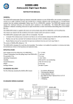
Wiring of normally closed and normally open detectors and other monitored circuits of dry
contact type into an alarm loop of the Type 6 is made similar to connection of intrusion detectors into
alarm loops of the type 4 (see Appendix E).
Entrance Alarm Loop (Type 7)
A loop of the Type 7 (Entrance) is intended to involve any intrusion detectors, both normally
open and normally closed, and powered either over the loop or separately.
This loop is considered to be in one of the following states:
Armed
The alarm loop is monitored, its resistance being normal
Disarmed
The alarm loop is not monitored
11
Arming Delay
The programmed Arming Delay has not yet expired
Entrance Alarm
The alarm loop has been broken
Intrusion Alarm
Since activation of the alarm loop the time of given Alarm Delay has
been expired
Arming Failed
An attempt to arm the loop has failed because the loop is activated
An Entrance alarm loop is operated similarly to an Intrusion alarm loop, except for this loop
switches to the Entrance Alarm status immediately after its activation. Then, if this alarm loop is not
disarmed or armed until the Alarm Delay has been expired, the loop switches to the Intrusion Alarm
status.
While the alarm loop is being in the Entrance Alarm status, no relay controlled in accordance
with one of the general-purposed executive programs (#1 – #8) or Siren program (# 12) is activated.
An alarm integration time for this type of alarm loops can be 70 ms or 300 ms depending on the
programmed value of the 300-ms Integration Time parameter.
Table 4.2 shows how the alarm loop resistances match with the states of an alarm loop of the
Type 7.
Intrusion detectors are wired into an alarm loop of the Type 7 similarly to connection of intrusion
detectors into alarm loops of the type 4 (see Appendix E).
Panic Alarm Loop (Type 11)
All kinds of normally closed and normally open panic buttons, pedals and so on can be brought
into a Panic alarm loop (Type 11).
This loop is considered to be in one of the following states:
Armed
The alarm loop is monitored, its resistance being normal
Disarmed
The alarm loop is not monitored
Arming Delay
The programmed Arming Delay has not yet expired
Panic Alarm
Activation of the loop has been detected
Arming Failed
An attempt to arm the loop has failed because the loop is activated
A Panic alarm loop is operated similarly to an Intrusion alarm loop, except for this loop switches
to the Panic Alarm status after it has been activated.
The Panic Alarm status is indicated only by the light indicators of the Signal-20M and can initiate
only those related relays which are programmed to operate in accordance with Alarm Output 1 (#10) or
Alarm Output 2 (#16) executive programs (the relay contacts being opened). The internal sounder of the
Signal-20M also is not activated upon a Panic Alarm.
An alarm integration time for this type of alarm loops can be 70 ms or 300 ms depending on the
programmed value of the 300-ms Integration Time parameter.
Table 4.2 shows how the alarm loop resistances match with the states of an alarm loop of the
Type 11.
Panic buttons are wired into an alarm loop of the Type 7 similarly to connection of intrusion
detectors into alarm loops of the type 4 (see Appendix E).
12
Programmable Auxiliary Alarm Loop (Type 12)
This type of alarm loops can be used to monitor conditions of various equipment and detectors,
including those which are not related directly with fire and intrusion alarms. Any detectors or devices
with dry contact or open collector outputs can be included into an alarm loop of the Type 12.
A Programmable Auxiliary alarm loop can be in one of five different states which match each to
its own resistance range. These states and resistance values matched with them are user programmable.
Accordingly, if a device can be in one of some different conditions and has several output contacts, this
device can be monitored by means of a single alarm loop. In such a case the output contact of the device
must be included into the alarm loop along with different additional or shunt resistors. By such a manner
the loop can be monitored for short and open failures.
Sound and light indication of the Signal-20M as well as the way this loop impacts on a related
relay (that is, the executive program assigned with the relay) are defined by the states this loop can reach.
Switching between statuses of a Programmable Auxiliary alarm loop is defined only by changing its
resistance and is not affected by any other loop parameters or network controller commands. The
integration time for switching between statuses is generally equal to 300 ms. But if an alarm loop of the
Type 12 has entered such status as Armed, Disarmed, Auxiliary Zone Restored, or any other “…
Restored”, the integration time for this status is equal to a programmed Arming Delay value.
A Programmable Auxiliary alarm loop is always monitored and cannot be blocked or disarmed. If
the arming command addressed to this loop is received, the device responds with the message about its
current status.
When states of alarm loops of the Types 12 are changed the Signal-20M transmits the network
controller relevant messages. The events due to Programmable Auxiliary alarm loop are not stored in the
non-volatile device memory. So, if during a loss of communication an alarm loop of the Programmable
Auxiliary Type has changed its status several times, then on restoring communications the network
controller will receive either a single message or no messages if the current status of the alarm loop is the
same as the last transmitted status.
The parameter Arming Delay (Exit Delay) defines the time in seconds in which the panel tries to
arm the alarm loop after receiving the relevant command. Non-zero Arming Delay is usually used for an
entrance alarm loop when after issuing an arming command the alarm loop can be violated by user
(protection of the entrance door). Moreover, if before arming the alarm loop a panel relay should be
activated (the executive program Switch On for a Time before Arming) then the alarm loop must have
a non-zero Arming Delay. Otherwise the relay will not switch because the time of activation of the relay
for this program cannot exceed Arming Delay.
Alarm Delay for an Entrance alarm loop (Type 7) is a delay of switching from The Entrance
Alarm status to the Intrusion Alarm status (the “entry delay”). It should be selected so that a user can
have enough time to disarm the alarm loop after entering the premises.
For a fire alarm loop (of the Type 1, 2, or 3) the Alarm Delay means the time of switching from
the Fire Pre-alarm status to the Fire Alarm status. Alarm loops of the Types 1 and 3 (with recognition of
double activation) can switch to the Fire Alarm status in case of activation of a second fire alarm in an
alarm loop. If Alarm Delay is equal to 255 s, the panel doesn’t enter the Fire Alarm mode by time
(unlimited delay). In such case alarm loops of the Type 1 and 3 can enter the Fire Alarm status only after
activation of a second detector in the alarm loop while an alarm loop of the Type 2 will enter the Fire
Alarm status on no conditions. For alarm loops of the Types 6 and 12 Alarm Delay defines the time of
restoring the alarm loop or the time of transition between states.
If on arming an alarm loop its resistance is less than normal, for example if a smoke detector has
responded, the panel automatically resets the alarm loop (shuts off power voltage of all the alarm loops
for 3 s). Loop Analysis Delay for any type of alarm loops is the duration of a pause after de-energizing it
and before analyzing it (on re-querying the status of a fire alarm loop and on arming). This delay
provides bringing detectors with high pre-operation time (damping time) into alarm loops of the panel. If
after “resetting" the alarm loop the detector powered via the loop returns to the quiescent mode for a
long time (consumes current heavily for a long time), it should be programmed with Loop Analysis
Delay which slightly exceeds the maximum pre-operation time of the detectors brought into the alarm
loop. The minimum hardware delay is 1 s.
13
The parameter Never Disarmed disables disarming the alarm loop by any way. This parameter is
usually to be set on for fire and panic alarm loops to avoid their accident disarming, for example by a
command from the network controller. If the alarm loop enters the Intrusion Alarm status, the Panic
Alarm status, the Fire Pre-alarm status, the Fire Alarm status, or the Arming Failed status then arming
and disarming the alarm loop will result in a trying top arm the alarm loop ("Alarm Reset"). As a result,
the alarm loop will enter the Armed status again (if the alarm loop resistance is normal) or in the Arming
Failed status (id the alarm loop is violated).
If the alarm loop has entered the Arming failed status (the alarm loop was violated in the moment
of arming) and for this alarm loop the attribute Auto Rearming After Failing has been set on then this
alarm loop will automatically enter to the Armed status as soon as the resistance of the alarm loop is
within the normal range for 3 s.
If the alarm loop has entered the Intrusion Alarm status, the Panic Alarm status, or the Fire Alarm
status and for this alarm loop the attribute Auto Arming After Alarm is set on then the alarm loop will
automatically enter the Armed status as soon as its resistance is being normal for the time equal fifteen
times Alarm Delay (in seconds). If Alarm Delay is set to zero the recovery time is 15 s.
The parameter Disarmed Loop Monitoring obliges the panel to monitor the alarm loop also in
the disarmed condition. If the resistance of the alarm loop is normal, the panel sends the network
controller a Disarmed Loop Restored message, but if the alarm loop is violated the panel sends the
network controller a Disarmed Loop Alarm. The integration time for generating a Disarmed Loop Alarm
is 300 milliseconds while for generating a Disarmed Loop Restored this time is equal to Alarm Delay.
The parameters Relay 1…5 Control assign the alarm loop with the relays of the panel. If a status
of the alarm loop must have an effect on a panel relay then the relevant parameter must be set on.
Otherwise the parameter should be set off.
If a panel relay is expected to be controlled by the network controller (centralized relay control)
then the parameters Relay 1…5 Control must be set on for all the alarm loops for the given relay.
If changing the alarm loop status must result in switching a relay on or off (in accordance with
the executive program for the relay) then the relay will be switched on/off not immediately but in time
equal to Relay 1…5 Activation Delay for this alarm loop. For the specific executive programs such as
9 ("Lamp"), 10 ("Alarm Output 1"), 13 ("Fire Output"), 14 ("Trouble Output"), 15 ("Fire Lamp"), and 16
("Alarm Output 2") (see Table 4.4) the parameter Relay 1…5 Activation Delay is ignored and the relay
is switched immediately after changing the status of the alarm loop.
The parameter Fire Loop Requery Prohibition disables repeated queries of status of alarm
loops of the Type 1 or 2 in case of a response of a single detector. If Fire Loop Requery Prohibition is
set on then activation of a single detector will switch the alarm loop to the Fire Pre-alarm status
immediately.
The 300-ms Integration Time parameter enables setting the integration time for intrusion alarm
loop (of the Types 4, 5, 7, 11). The integration time of 300 milliseconds corresponds to the value "On"
while 70 milliseconds correcp0onds to the value "Off". To increase reliability of the panel operation and
to decrease false alarms, we recommend to set the integration time to the value of 70 ms only when
strictly necessary.
The 10 % Deviation Blocking parameter disables analysis of sharp jumps in the resistance (more
than 10 % of a steady state value) for intrusion alarm loops, if the distinction doesn’t run out of the
normal range. Set this parameter for the alarm loops which comprises detectors producing essential
ripples.
14
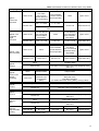
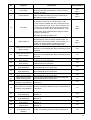
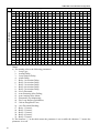
Table 4.2. Resistance Values for Different Alarm Loop States
Loop Type
Alarm Loop States
Fire Alarm
Fire Pre-alarm
(two or more
(a smoke detector
smoke detectors
has responded)
have responded)
Short circuit
Type 1 –
Smoke Two
Threshold
*
Less than 100 Ω
Type 2 – Fire
Combined
Single
Threshold
100 Ω to 1.56 K
Type 7 –
Entrance
Type 11 –
Panic
Type 12 –
Programmable
Auxiliary
2.2 to 5.4 K
More than 6.6 K
Open circuit
*
Short circuit
A smoke detector
has responded
(Fire Pre-alarm,
Fire Alarm)
Norm
A heat detector
has responded
(Fire Pre-alarm,
Fire Alarm)
Less than 100 Ω
100 Ω to 1.8 K
2.2 to 5.4 K
6.6 K to 14.4 K
More than 16 K
Short circuit
Norm
Fire Pre-alarm
(a heat detector
has responded)
Fire Alarm
(two or more heat
detectors have
responded)
Open circuit
Less than 1.8 K
3.0 K to 5.4 K
6.6 K to 11 K
12.5 K to 22.5 K
More than 25 K
Type 4 –
Intrusion
Type 6 –
Auxiliary
Open circuit
1.1 to 1.8 K
* Depends on the load current of the
loop
Type 3 – Heat
Two Threshold
Type 5 –
Intrusion with
Tamper
Monitoring
Norm
Norm
Intrusion Alarm
2.2 K to 10 K
Less than 1.8 K, more than 12 K or has jumped by more
than 10 %
Norm
Intrusion Alarm
Tamper Alarm
2.2 to 5.4 K
Less than 1.8 K or
less than 6.6 K
(in the Armed
status)
6.6 K to 9.0 K;
More than 20 K;
Less than 100 ohms.
(for states Disarmed, Arming Delay, Arming Failed)
Auxiliary Zone Restored
Auxiliary Zone Alarm
2.2 to 5.4 K
Less than 1.8 K or more than 6.6 K
Norm
Entrance / Intrusion Alarm
2.2 to 5.4 K
Less than 1.8 K, more than 6.6 K or has jumped by more
than 10 %
Norm
Panic Alarm (Attack)
2.2 to 5.4 K
Less than 1.8 K, more than 6.6 K or has jumped by more
than 10 %
Status 1*
Status 2*
*
*
*
Status 3*
*
*
Status 4*
*
*
Status 5*
*
Less than R1
R1 to R2
R2 to R3
R3 to R4
More than R4
* – The states of alarm loops and threshold values of alarm loop resistance are to be
programmed (see Clause 5.4.2)
15
4.1.3 Short-time violations of the alarm loops for a time in which the panel doesn’t switch to an
alarm mode ("Integration Time" of an alarm loop), last:
− 50 ms and less for intrusion alarm loops if 300 ms Integration Time is off;
− 250 ms and less for all other alarm loops if 300 ms Integration Time is on.
Violations of the alarm loops for a time in which the panel enter an alarm mode last:
− 70 ms and more for intrusion alarm loops if 300 ms Integration Time is off;
− 300 ms and more for intrusion alarm loops and alarm loops of the Type 12 if 300 ms
Integration Time is on.
For alarm loops of the Types 1, 2, 3 the violation time of the alarm loop after which the panel
enters an alarm mode can be 300 ms to 3 s depending on the nature of transition process in case of the
violation. If the alarm loop comprises detectors with high values of internal capacity then the integration
time in case of a violation will increase inversely to the rate of the transition process. The minimum rate
of voltage’s changing in the alarm loop for maximum integration time is 0.5 V/s.
4.1.4 The panel provides powering current-consumed two-wire intrusion and fire detectors from
the alarm loops.
The number of detectors per an alarm loop is estimated with the formula:
N = Im / i , where:
N stands for the number of the detectors in the alarm loop;
Im stands for the maximum load current:
− Im = 3 mA for alarm loops of the Types 1, 4, 6, 7, 11, 12;
− Im = 1.2 mA for alarm loops of the Type 2;
i stands for the current consumed by a detector in the quiescent mode, mA.
For an alarm loop of the Type 1 (Smoke Two Threshold) then the detectors in use must be operable in
case of detector voltage’s dropping to 12 V.
4.2
Relays
The relays of the panel can be controlled by any of the two ways:
– In accordance with a states of the alarm loops assigned with the relay (local control);
– By commands of the network controller (centralized control).
To control relays depending on states of the alarm loops, you should set the links between the
relay and the alarm loops by means of the parameters Relay 1…5 Control for the relevant alarm loops,
set Relay 1…5 Activation Delay, and set Executive Program and Relay Activation Time for each of
the relays.
Executive program defines how the relay will be controlled for various states of the alarm loops
assigned with the relay. The executive programs are described in Table 4.4.
Relay Activation Time gives the time of activation (switching off) the relay for the executive
programs which have time parameters ("Switch On/Off for a Time").
For all the executive programs except for No.No.9, 10, 13, 14, 15, 16 (see Table 4.4), switching
on (off) the relay when an alarm loop status changes will be delayed for the time specified in the
parameter Relay Activation Delay for each the alarm loop. Thus, for various alarm loops of the panel
assigned with the same relay output you can program various values of activation delay.
For executive programs No.1 to No.8 (general-purpose programs), 11 ("ASPT"), 12 ("Siren"), 33
("ASPT-1"), 34 ("ASPT-A"), 35 ("ASPT-A1") activation of an Auxiliary alarm loop (Type 6) assigned
with the relay disables switching on the relay. If after recovering the Auxiliary alarm loop the conditions
of switching on the output from other alarm loops persist then for programs with unlimited activation
time (the programs 1, 2, 5, 6) as well as for programs 11 ("ASPT") and 33 ("ASPT-1") the relay output
will be switched on again while for the programs 3, 4, 7, 8, 12, 34, and 35 the relay output will not be
switches on. Thus, a violation of an Auxiliary alarm loop stops executing of general-purpose programs
with unlimited activation time and the programs "ASPT" and "ASPT-1" and disables the generalpurpose executive programs with limited activation time as well as the programs "Siren", "ASPT-A",
and "ASPT-A1".
If in the panel configuration a link of the relay with the alarm loops is programmed then remote
control commands from the network controller (over the RS-485 interface) will be ignored. Local
control of a relay is of more priority than centralized control.
16
In order a panel relay can be controlled remotely (by commands of the network controller:
– In the panel configuration disable the links between the relay and alarm loops (set the
parameter Relay 1…5 Control for all the alarm loops);
– Assign the relay with any executive program implying a proper initial condition ("On" or
"Off");
– In the database of the network controller assign the relay with relevant partitions and define
the executive program, the activation delay, and the relay activation time.
Executive Program in case of not assigning the relay with the alarm loops defines only the
initial condition of the relay – the condition which the relay has after powering up the panel. For most
cases, for that relay of the panel which is to be controlled centrally you need to define Executive
Program which implies “Off” initial conditions, for example the program 1 ("Switch On"). After
powering up the panel and till receiving a remote control command which switches the relay to the
position corresponding to the current status of the partitions assigned with the relay some time can come,
so if a centralized control command is in use which implies “On” initial condition then it is advisable to
switch the relay to the “On” condition just after powering up. For doing so, aby executive program
should be assigned to the relay which has “On” initial condition, for example the program 2 ("Switch
Off").
Table 4.3. Relay Configuration Parameters
Parameter
Executive
Program
Relay
Activation Time
Relay ON/OFF Events
Description
Defines the behavior of the relay output
depending on states of the alarm loops
assigned to the relay and the initial state of
the relay
Defines the time interval for which the relay
will be switched on or off if the assigned
executive program implies the limited
activation time
Provides transmitting events about output
condition changes in order to display the
relay state by external annunciators and
logging events about switching the relay on
and off in the system log
Range
1…37
0 s to 8192 s
(up to 2 hours 16 minutes 32s)
in increments of 0.125 s
On / Off
1 – Without Monitoring
Monitor For
Defines the tactics of monitoring of external
circuits of outputs “relay 4” (K4) and “relay 5”
(K5)
2 – Open Failure
3 – Short Failure
4 – Open and Short Failure
Executive Program defines the method the relay output will be controlled depending on the
current status of the alarm loops related with the relay output (for local control) or the initial condition of
the relay after powering the Signal-20M until receiving a first control command from the network
controller (for centralized control). Table 4.4 describes all available executive programs for the Signal20M.
Relay Activation Time gives the time interval the relay will be activated for (switched on or off)
if the assigned executive program implies the limited activation time. The maximum time interval the
relay can be activated for is that is 65535 intervals of 0.125 s each.
Monitor For parameters for outputs “relay 4” (K4) and “relay 5” (K5) define the kind of troubles
of external device circuits connected to these outputs which will be monitored for. The failures such as
open circuit failures, short circuit failures, or both open and short failures will be monitored without
regard to relay output’s being switched on or off. Table 4.5 shows how the Signal-20M considers the
values of load circuit resistances to be matched to the various circuit conditions.
17
Relay ON/OFF Events can be set on individually for each relay output. If the parameter is set on
then any change of output state is transmitted to a network controller as an event with specifying the
mode of switching.
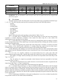
Table 4.4. Executive Programs for Relay Outputs
No.
Program
Description
Initial Condition
0
Remote Control
Off
1
Switch On
2
Switch Off
3
Switch On for a Time
4
Switch Off for a Time
5
Blink From Off Condition
6
Blink From On Condition
7
Blink for a Time From Off
Condition
8
Blink for a Time From On
Condition
The relay is controlled only remotely
The relay is switched on if there is an Intrusion Alarm or
Fire Alarm
The relay is switched off if there is an Intrusion Alarm or
Fire Alarm
The relay is switched on for a specified time if there is
an Intrusion Alarm or Fire Alarm
The relay is switched off for a specified time if there is
an Intrusion Alarm or Fire Alarm
The relay is switched on/off once per second if there is
an Intrusion Alarm or Fire Alarm
The relay is switched on/off once per second if there is
an Intrusion Alarm or Fire Alarm
The relay is switched on/off once per second for a
specified time if there is an Intrusion Alarm or Fire
Alarm
The relay is switched on/off once per second for a
specified time if there is an Intrusion Alarm or Fire
Alarm
In case of a Fire Alarm the relay is switched on/off
alternately twice per second
Off
On
Off
On
Off
On
Off
On
In case of a Fire Prealarm the relay is switched on for a
short time every second
9
Lamp
In case of an Intrusion Alarm, or Entrance Alarm, or
Arming Failed the relay is switches on/off alternately
once per second
See
Note 1
In case of a Trouble the relay is switched on for a short
time once per two seconds
If an alarm loop is armed the relay is switched on
If all alarm loops are disarmed the relay is switched off
10
11
Alarm Output 1
ASPT
If all the alarm loops related with the relay are armed
then the relay is switched on, otherwise the relay is
switched off
The relay is switched on for a given time if two or more
alarm loops related with the relay have Fire Alarm
status and there are no Auxiliary loops broken. The
broken Auxiliary loop will block switching on. If the
Auxiliary loop is broken while the Relay Activation Delay
has not yet expired then, after recovering of the loop,
the relay output will be switched on for a specified time.
(That is, breaking of the Auxiliary loop temporary blocks
activation delay counting.)
See
Note 1
Off
In case of a Fire Alarm the relay is switched on/off for a
specified time in mode ‘On for 1.5s and Off for .5s’
12
Siren
In case of a Fire Prealarm the relay is switched on/off
for a specified time in mode ‘On for .5s and Off for 1.5s’
In case of an Intrusion Alarm the relay is switched on
for a specified time
Otherwise the relay is off
18
Off
No.
Program
13
Fire Output
14
Trouble Output
Description
If the related loop has Fire Alarm or Fire Prealarm
status then the relay is switched on, else the relay is
switched off (open)
If there are related alarm loops having Trouble, Arming
Failed, or Disarmed status, the relay is switched off.
Otherwise the relay is switched on
In case of a Fire Alarm the relay is switched on/off twice
per second in mode ‘On for .25s and Off for .25s’
Initial Condition
See
Note 1
See
Note 1
In case of a Fire Prealarm the relay is switched on/off
once per second in mode ‘On for .25s and Off for .75s’
15
Fire Lamp
In case of a Trouble the relay is switched on/off once
per 2 seconds in mode ‘On for .25s and Off for 1.75s’
See
Note 1
If all the alarm loops related with the relay are armed
the relay is switched on
Otherwise, the relay is switched off
16
17
18
19
20
21
22
23
24
25
26
27
28
29
30
31
If all the alarm loops related to the relay are armed or
disarmed (that is, there is neither Intruder Alarm, nor
Alarm Output 2
Silent Alarm, nor Entrance Alarm, nor Fire Alarm, nor
Trouble, nor Arming Failed condition) the relay is
switched on, otherwise the relay is switches off
If the related alarm loop is being armed (the Arming
Switch On For a Time
Delay has not yet expired) the relay is switched on for a
Before Arming
given time
If the related alarm loop is being armed (the Arming
Switch Off For a Time
Delay has not yet expired) the relay is switched off for a
Before Arming
given time
Switch On For a Time
If any related alarm loop has just been armed the relay
Upon Arming
is switched on for a given time
Switch Off For a Time
If any related alarm loop has just been armed the relay
Upon Arming
is switched off for a given time
Switch On For a Time
If any related alarm loop has just been disarmed the
Upon Disarming
relay is switched on for a given time
Switch Off For a Time
If any related alarm loop has just been disarmed the
Upon Disarming
relay is switched off for a given time
Switch On For a Time
If arming of any related alarm loop has just failed the
When Arming Failed
relay is switched on for a given time
Switch Off For a Time
If arming of any related alarm loop has just failed the
When Arming Failed
relay is switched off for a given time
Switch On for a Time Upon If there is an Auxiliary Alarm the relay is switched on for
Auxiliary Loop Breaking a given time
Switch Off for a Time Upon If there is an Auxiliary Alarm the relay is switched off for
Auxiliary Loop Breaking a given time
Switch On
Upon Disarming
Switch Off
Upon Disarming
Switch On
Upon Arming
Switch Off
Upon Arming
Switch On
Upon Auxiliary Loop
Breaking
If at least one related loop is disarmed the relay is
switched on
If at least one related loop is disarmed the relay is
switched off
If at least one related loop is armed the relay is
switched on
If at least one related loop is armed the relay is
switched off
In case of an Auxiliary Alarm the relay is switched on
See
Note 1
Off
On
Off
On
Off
On
Off
On
Off
On
Off
On
Off
On
Off
19
No.
Program
Description
32
Switch Off
Upon Auxiliary Loop
Breaking
Initial Condition
In case of an Auxiliary Alarm the relay is switched off
On
The relay is switched on for a specified time if the alarm
loop has got Fire Alarm status and there are no
broken Auxiliary alarm loops. If an Auxiliary alarm loop
is broken before Relay Activation Delay has not yet
expired then, when the loop is recovered, the relay
output will be switched on for a specified time. (That is,
breaking of the Auxiliary loop temporary blocks
activation delay counting.)
The relay is switched on for a specified time if two or
more alarm loops related with the output have got Fire
Alarm status and there are no broken Auxiliary alarm
loops. A broken Auxiliary loop cancels activation the
relay, that is, the Auxiliary loop being recovered, the
output will NOT be switched on
The relay is switched on for a specified time if the alarm
loop has got Fire Alarm status and there are no broken
Auxiliary alarm loops. A broken Auxiliary loop cancels
activation the relay, that is, the Auxiliary loop being
recovered, the output will NOT be switched on
33
ASPT-1
Off
34
ASPT-A
35
ASPT-A1
36
Switch On Upon
Temperature Increase
If the alarm loop has got the High Temperature **
status the relay is switched on
Off
37
Switch On Upon
Temperature Decrease
If the alarm loop has got the Low Temperature ** status
the relay is switched on
Off
Off
Off
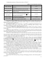
Notes:
1) Relay’s behavior is defined by the state of a group of the alarm loops assigned with the relay;
2) Relay Activation Time must be equal to zero for the output assigned to an Auxiliary alarm loop;
3) Only the Auxiliary Programmable alarm loop (of the Type 12) can enter High Temperature or Low
Temperature condition if these states are programmed for this loop.
Table 4.5. States of Output Circuit Depending on the Voltage on the Output’s Minus Terminal
Norm
Open Circuit
Any voltage in the range of
0.35 V to 4.0 V
Short Circuit
Output ON
Output OFF
Output ON
Output OFF
Less than 0.05 V
More than 4.1 V
More than 4.5 V
Less than 0.3 V
Table 4.6. Output Status Indicator Behavior
No.
Output Status
Indicator Behavior
1
Off
Off
2
On
Lit in red
3
Switches on and off alternately
Turns on in red interruptedly in phase with the output
4
A trouble of the monitored
circuit
(for "relay 4" and "relay 5")
Flashes in yellow:
on for 0.125 s / off for 0.875 s
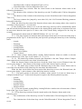
4.3
Device Parameters
4.3.1 The configuration parameters of the panel define specifics of its operation as part of an
Orion system and provide limitation of some control functions with due regard to safety requirements of
the protected premises.
20
Configuration parameters of the panel are shown in Table 4.7.
Table 4.7. Panel Configuration Parameters
Parameter
Digits in PIN Code
Prevent Factory Reset
Both Power Inputs
Monitoring
Password Confirmed
Siren Silence
Network Address
Response Pause
Description
Range
Defines the length (the number of digits) in a User
password
Prevents a possibility to reset current settings of the
panel to their default (factory) values manually
Defines the way the panel is switches to the Power
Failed mode: in case of a power failure at one or
both power inputs
2…6
On / Off
On / Off
The built-in sound alarm and the external sound
alarm can be silenced using the button
after typing a User password
Defines the address of the panel while being
connected to the RS-485 interface
Defines the admissible delay for the panel to
respond to a network controller request
only
On / Off
1…127
1.5 ms to 500 ms
in intervals of 0.125 ms
The parameter Digits in PIN Code provides programming a number of digits while typing a User
password (PIN) on the panel keypad. The minimum number of digits is two while the maximum value of
digits a User password can contain is six.
Prevent Factory Reset can be used if there is a possibility of unauthorized (unintended) reset of
the current settings of the panel to their factory values by maintaining staff’s pressing a code
combination on the tamper switch of the panel (see Clause 5.6.6).
The parameter Both Power Inputs Monitoring defines the condition for the panel to switch the
Power Failed mode: in case of a power failure at one power input or in case of power failures at both
power inputs.
If Both Power Inputs Monitoring is set on, the panel will switch to the Power Failed mode when
the voltage has dropped below 10 V at least at one power input; and the panel will return to the quiescent
mode when at both power inputs the voltage have exceeded 11 V.
If Both Power Inputs Monitoring is set off, the panel keeps operation in the quiescent mode till at
least at one power inputs is higher than 10 V; and the panel will switch to the Power Failed mode if the
maximum voltage at both power inputs has dropped below 10 V. The panel will return to the quiescent
mode if a voltage at one of the outputs has exceeded 11 V.
If unauthorized persons can have an access to the panel, setting on the parameter Password
Confirmed Siren Silence disables silencing of the built-in sounder as well as the external sound alarms
by pressing the button
. In such case, to shut off the internal sounder and the external sound alarms
a user should type a User password which code is enrolled in the panel. The button
silences only
the alarms which are connected to a relay operated by the executive program 12 (Siren).
Network Address is designed to identify the panel exactly within the Orion system. The panel
sends messages and receives commands from the network controller only using the address which is
specified by this parameter. Network Address must be unique for each the device in the Orion system.
Adjusting the parameter Response Pause enables using the panel in systems with a complicated
network configuration in cases when there could be delays in the communication channel on changing
data direction. For example, in case of converting the RS-485 interface into another interfaces intended
to translate data over local area networks, fiber-optics communication channel, or radio channel.
Current values of Network Address and Response Pause can be unset to their factory (default)
values in the Operator mode (see Clause 5.6).
4.3.2 To adjust the panel for a specific application and to use the panel’s features optimally, any
of the parameters of the panel itself, of the alarm loops or the relays can be edited using the program
UProg.exe or Orion Database Administrator tools.
4.3.3 Passwords (PIN Codes).
The panel provides entering, writing, deleting, and changing parameters of the following kinds of
passwords:
21
− User passwords;
− Operator password;
− Administrator password.
ARM or
The panel is to be switched to the mode of entering a password by pressing
.
Exiting the mode of entering the password is carried out:
− Automatically after entering the last digit of the password;
− After elapsing the timeout of 30 s;
− On pressing
.
For typing a password (PIN code) loop buttons since 1st to 10th are used. Loop buttons 11th to 20th
are not used while typing a password.
4.3.3.1 A User password provides combining alarm loops with any numbers to a single group and
arm / disarm whether an individual alarm loop from this group or the group as a whole. In doing so, the
user password can be assigned with the following control rights for each the alarm loop:
− Arming and disarming;
− Without rights to arm (disarming only);
− Without rights to disarm (arming only).
The number of User passwords is 64.
The number of digits in a User password is defined by Digits in PIN Code.
4.3.3.2 The Operator password is used by persons who maintain and adjust the panel. The
Operator password cannot arm or disarm alarm loops, or change User passwords or the Administrator
password. On typing the Operator password, the following actions become available:
− Resetting the network address;
− Starting the Diagnostic mode;
− Changing the Operator password;
− Factory resetting.
The number of Operator passwords is one.
The number of digits in the Operator password is six.
4.3.3.3 The Administrator password is used by persons who do business at the protected
premises. The Administrator password has no rights to arm and disarm the alarm loops or change
configuration parameters of the panel. On typing the Administrator password the following actions
become available:
− Adding new User passwords or changing rights of the existing passwords;
− Changing the codes of the User passwords;
− Deleting all User passwords;
− Changing the Administrator password.
The number of Administrator passwords is one.
The number of digits in the Administrator password is six.
4.4
Operation Modes
The panel provides operating in the following modes:
− Pre-Operation Mode;
− Quiescent Mode;
− Power Failure Mode;
− Password Enter Mode;
− Operator Mode;
− Administrator Mode;
− Diagnostic Mode;
− Device Failure Mode.
Please refer to Table 4.8 to see READY LED’s behavior in various operation modes.
4.4.1 As soon as supply voltage has been applied to the power input terminals of the panel, the
panel switches from its no-voltage condition to the Pre-Operation mode. The time of panel’s being in the
Pre-Operation mode is defined by the requirements of Clause 1.12.
22
4.4.2 As soon as the Pre-Operation mode has finished, the panel enters the quiescent mode
when it performs its basic functions monitoring and analyzing states of alarm loops, controlling relays
and light and sound alarms, and communicates with the network controller.
The panel sounds with a melody to enable user to easily recognize that the panel has successfully
switched to the quiescent mode.
4.4.3 The panel switches from the quiescent mode to the Power Failure mode if the power
supply voltage at one or both power inputs has dropped below 10 V (see Clause 4.3.1 for Both Power
Inputs Monitoring). In this mode the panel keeps operating but issues warning signals by its READY and
FAULT LEDs and transmits a Power Failed message.
If the power supply voltage has dropped below 9 V the panel shuts off.
If then the power supply voltage at one or both power inputs has increased above 11 V the panel
automatically switches from the Power Failure mode to the quiescent mode generating a Power Restored
message.
4.4.4 The panel switches from the quiescent mode to the Password Enter mode when one of the
buttons
and DIS. To get more information about this operation mode please refer to Clause 5.5.2.
4.4.5 The panel switches from the quiescent mode to the Operator mode on typing an Operator
PIN code on the panel keypad. To get more information about this mode please refer to Clause 5.6.
4.4.6 The panel switches from the quiescent mode to the Administrator mode on typing an
Administrator PIN code on the panel keypad. To get more information about this mode please refer to
Clause 5.7.
4.4.7 The panel switches from the Operator mode top the Diagnostic mode on pressing the “12”
button. To get more information about this mode please refer to Clause 5.8.
4.4.8 The panel enters the Device Failure mode in case of it’s detecting a failure while testing
the program memory of the microprocessor. The program memory is tested each time the panel’s power
is turned on.
When the panel has switched to the Device Failure mode:
− READY LED is off;
− FAULT LED switches on for a second and switches off for a second alternately;
− The sounder issues interrupted sounds;
− Other indicators are off.
If the panel switches to the Device Failure mode just after powering on, please update its
firmware. For doing so:
1. Forward the Bolid Company the relevant request specifying the panel version.
2. As a response, you will receive the program ORION_PROG.exe and an e-file with
microprocessor firmware.
3. Connect the panel to a PC via one of the interface converters such as S2000-USB or S2000-PI.
4. Run ORION_PROG.exe and turn the panel power on.
5. Follow on-screen instruction until firmware has been updated. The process of writing the
program into the panel is being displayed by FAULT LED while the sounder silences. Firmware
having been updated, the panel enters the Pre-Operation mode.
23
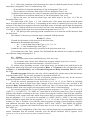
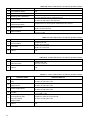
Table 4.8. READY LED Behavior in Different Operation Modes
No.
Operation Mode
1
2
Pre-Operation Mode
Quiescent Mode
3
Entering User’s Password
4
Power Failure
5
Operator Mode,
Administrator Mode
6
Diagnostic Mode
7
Device Failure
Indicator Behavior
Off
Lit with green
Lit in red and green alternately:
0.5 s in red, then 0.5 s in green and so on
Turns on interruptedly in yellow:
0.125 s on and 0.875 s off, and so on
Flashes twice in red and green alternately every second
Flashes in red twice per second:
0.25 s on and 0.25 s off
FAULT LED switches on and off alternately:
1 s on / 1 s off
Table 4.9. FIRE LED Behavior in Different Operation Modes
No.
Operation Mode
1
Fire Pre-Alarm
2
Fire Alarm
3
Others
Indicator Behavior
Flashes with red:
0.25 s on / 0.75 s off
Flashes with red:
0.25 s on / 0.25 s off
Off
Table 4.10. ALARM LED Behavior in Different Operation Modes
No.
Operation Mode
Indicator Behavior
1
Intrusion Alarm
Flashes with red:
0.5 s on / 0.5 s off
2
Others
Off
Table 4.11. FAULT LED Behavior in Different Operation Modes
No.
1
2
24
Operation Mode
Open or short failure of the alarm
loop
Open or short failure of the
output circuit
Indicator Behavior
Flashes in yellow once per second:
0.125 s on and 0.875 s off
Flashes in yellow once per second:
0.125 s on and 0.875 s off
Flashes in yellow once per second:
0.125 s on and 0.875 s off
Alternately turns on in yellow and turns off:
1 s on and 1 s off
3
Power supply failure
4
Trouble
5
For an alarm loop of the Type 12:
Fire equipment fault,
AC power failed,
Battery failed
Flashes in yellow once per second:
0.125 s on and 0.875 s off
6
Others
Off
5
Utilization
5.1
Preparation for Using
5.1.1 Safety precautions when preparing the panel for usage:
− There are no potential hazard circuits within the Signal-20M;
− DO SHUT OFF the panel power before mounting, wiring, or maintaining the panel;
− Mounting and maintaining of the device must be implemented by qualified specialists.
5.1.2 Mounting the panel:
− The panel can be attached on walls or other constructions of the premises at places protected
against atmospheric fallouts and mechanical damage;
− Attach the panel on the wall at a convenient place. If the panel is attached in an unwatched
premises, fix it at a height of at least 2.2 m above the floor;
− Mount and wire the panel in accordance with the connection diagram in Appendix C.
Isolating diodes for outputs K4 and K5 must be wired as close to the light or sound alarm
contacts as possible.
If the output K4 or/and K5 is/are not in use “close” it/them by a 1 K – 0.5 W resistor.
5.1.3 Connecting RS-485 Interface Bus.
To connect the panel to the network controller via the highway interface RS-485, do the
following:
− Connect A and B terminals of the panel PCB to lines A and B of the RS-485 interface
respectively;
− Connect 0V circuit of the panel to the similar circuits of the previous device and the next
device in the RS-485 interface bus (this is not necessary if the devices are connected to the same power
supply);
− Unless the panel is not the end device in the interface bus (the first device or the last device),
remove the jumper on the panel’s PCB. The jumper is located near the A and B contacts and includes a
620 Ω EOL resistor in the interface bus.
On wiring the RS-485 interface it is recommended to implement the “bus” network configuration
(to connect devices in a chain). If you need to have a sizable branch (more than 50 m) from the common
RS-485 bus (for example, to reduce the length of the cable) in is recommended to add an interface
repeater S2000-PI at the place of the branch. You can use no more than 10 interface repeater (no more
than 10 branches) for a single RS-485 segment. The number of sequentially wired S2000-PI repeaters
(the number of segments) is not limited.
5.1.4 Changing the Initial Configuration of the Panel.
If the panel is to be operated along with other devices in an Orion system, it must be assigned to a
unique (distinguished from every other) network address ranged 1 to 127. For doing so connect the panel
to the network controller (other devices must be disconnected from the interface) and change the network
address by means, for example, UProg.exe.
Adjusting the panel for a specific application and using the panel features optimally can require
changing some configuration parameters.
The configuration parameters on receipt have values shown in Tables 5.1, 5.2, and 5.3.
Table 5.1. Panel Factory Values
No.
Parameter
Value
1
Network Address
127
2
Set Response Pause
3
Number of Digits in PIN Code
4
Prohibit Factory Reset
Off
5
Both Power Inputs Monitoring
Off
6
Password Confirmed Siren Silence
Off
1.5 milliseconds
4
25
Table 5.2. Panel Default Configuration
Alarm Loops
Configuration Parameters (see Notes)
№
1
2
3
4
5
6
7
8
9
10
11
12
13
14
15
16
17
18
19
20
21
1
4
0
1
0
0
0
0
0
0
-
+
-
-
-
+
-
+
-
-
-
-
2
4
0
1
0
0
0
0
0
0
-
+
-
-
-
+
-
+
-
-
-
-
3
4
0
1
0
0
0
0
0
0
-
+
-
-
-
+
-
+
-
-
-
-
4
4
0
1
0
0
0
0
0
0
-
+
-
-
-
+
-
+
-
-
-
-
5
4
0
1
0
0
0
0
0
0
-
+
-
-
-
+
-
+
-
-
-
-
6
4
0
1
0
0
0
0
0
0
-
+
-
-
-
+
-
-
+
-
-
-
7
4
0
1
0
0
0
0
0
0
-
+
-
-
-
+
-
-
+
-
-
-
8
4
0
1
0
0
0
0
0
0
-
+
-
-
-
+
-
-
+
-
-
-
9
4
0
1
0
0
0
0
0
0
-
+
-
-
-
+
-
-
+
-
-
-
10
4
0
1
0
0
0
0
0
0
-
+
-
-
-
+
-
-
+
-
-
-
11
4
0
1
0
0
0
0
0
0
-
+
-
-
-
+
-
-
-
+
-
-
12
4
0
1
0
0
0
0
0
0
-
+
-
-
-
+
-
-
-
+
-
-
13
4
0
1
0
0
0
0
0
0
-
+
-
-
-
+
-
-
-
+
-
-
14
4
0
1
0
0
0
0
0
0
-
+
-
-
-
+
-
-
-
+
-
-
15
4
0
1
0
0
0
0
0
0
-
+
-
-
-
+
-
-
-
+
-
-
16
4
0
1
0
0
0
0
0
0
-
+
-
-
-
+
-
-
-
+
-
-
17
4
0
1
0
0
0
0
0
0
-
+
-
-
-
+
-
-
-
+
-
-
18
4
0
1
0
0
0
0
0
0
-
+
-
-
-
+
-
-
-
+
-
-
19
4
0
1
0
0
0
0
0
0
-
+
-
-
-
+
-
-
-
+
-
-
20
7
60
1
30
0
0
0
0
0
-
+
-
-
-
+
-
-
-
+
-
-
Notes:
а) The number refer to the following parameters:
1 - Loop Type;
2 - Arming Delay;
3 - Loop Analysis Delay;
4 - Alarm Delay;
5 - Relay 1 Activation Delay;
6 - Relay 2 Activation Delay;
7 - Relay 3 Activation Delay;
8 - Relay 4 Activation Delay;
9 - Relay 5 Activation Delay;
10 - Never Disarmed;
11 - Auto Rearming After Failing;
12 - Auto Arming After Alarm;
13 - Disarmed Loop Monitoring;
14 - Fire Loop Requery Prohibition;
15 - 300-ms Integration Time;
16 - 10% Deviation Blocking;
17 - Relay 1 Control;
18 - Relay 2 Control;
19 - Relay 3 Control;
20 - Relay 4 Control;
21 - Relay 5 Control.
б) The character "+" in the table means the parameter is set on while the character "-" means the
parameter is set off.
26
Table 5.3. Relay Factory Values
Parameter
Relay Number
1
2
3
4
5
Executive Program
Activation Time, s
Relay ON/OFF Events
10
8192
Off
10
8192
Off
10
8192
Off
9
8192
Off
12
120
Off
Monitor For
–
–
–
4
4
WARNING: The new parameters come into effect only after the panel has been de-energized and
powered up again.
5.2
Fire Alarms
The panel operates in the fire alarm mode if at least one alarm loop is programmed with the Type
1, or 2, or 3. For such loops the panel provides operating each loop in the following statuses:
− Armed;
− Disarmed;
− Arming Delay;
− Arming Failed;
− Fire Signal;
− Fire Pre-Alarm;
− Fire Alarm;
− Trouble.
Panel’s indication and sound signaling are described in Tables 5.4, 5.5.
5.2.1 An alarm loop is considered to be in the Armed status if it has just been armed and its
resistance is normal. Short-time violations of the armed fire alarm loop for a time within 250
milliseconds are not considered as fire alarms.
5.2.2 If the alarm loop is configured with a non-zero Arming Delay, then on arming it switches
to the Arming Delay mode. If the alarm loop is activated within the time of delay this will not result in
switching to an alarm mode.
5.2.3 When Arming Delay has expired and if the alarm loop’s resistance is normal, the alarm
loop switches to the Armed mode. Otherwise, if Arming Delay has expired but the alarm loop’s
resistance hasn’t yet been normal, the alarm loop enters in the Arming Failed status.
If Auto Rearming After Failing is set on for the alarm loop, this one will be automatically armed
and switches from the Arming Failed mode to the Armed mode in case of its resistance has been normal
more than 3 s.
5.2.4 In case of a step-like violation of an armed alarm loop for a time more than 300
milliseconds the panel registers the violation and switches the alarm loop to one of the following modes:
− Fire Signal, if a single smoke (normally open) detector has responded in the alarm loop of the
Type 1 or Type 2;
− Fire Pre-Alarm, if a single heat (normally closed) detector has been responded in the alarm
loop of the Type or Type 3;
− Fire Alarm, if simultaneously two smoke detectors or two heat detectors have responded in the
alarm loop of the Type 1 or Type 3 respectively;
− Trouble, if an open or short failure of the alarm loop has appeared.
5.2.5 An alarm loop of the Type 1 or Type 2 switches from the Armed status to the Fire Signal
status if a response from a single smoke detector has been registered. In this case the panel re-queries the
status of the alarm loop by resetting the activated alarm loop and waiting for its repeated response. If a
detector within the alarm loop responds repeatedly within a minute, the panel switches the alarm loop in
the Fire Alarm status, otherwise (no detector has responded repeatedly) the panel returns the alarm loop
to the Armed status.
If Fire Loop Requery Prohibition in the panel configuration is set on for an alarm loop then this
loop switches to the Fire Pre-Alarm status immediately.
27
5.2.6 Fire alarm loops switch to the Fire Pre-Alarm status after a response of a heat detector or a
repeated response of a smoke detector. The duration of each alarm loop’s being in the Fire Pre-Alarm
status is limited by the programmed Alarm Delay time. This delay enables analyzing the circumstances
and, in necessary, cancelling an alarm before generation a signal to start a fire-fighting equipment.
After termination of the Fire Pre-Alarm status the alarm loop switches to the Fire Alarm status.
Alarm loops of the Type 1 or 3 can be switched from the Fire Pre-Alarm status before elapsing of the
delay if the panel registers and activation of another detector (there are two or more responded
detectors).
If the programmed Alarm Delay is equal to 255, then alarm loops of the Types 1 and 3 can switch
to the Fire Alarm status only after activation of two or more detectors while an alarm loop of the Type 2
will keep the Fire Pre-Alarm status until the alarm has been unset.
Fire Pre-Alarm status is indicated interruptedly by the FIRE LED: 0.25 s FIRE LED is on and
0.75 s Fire LED is off alternately.
5.2.7 An alarm loop enters the Fire Alarm status either in case of activation of two detectors in
a single alarm loop of the Type 1 or 3 or after termination of the Fire Pre-Alarm mode. When the alarm
loop has entered the Fire Alarm status, among others the relays are controlled in accordance with the
programs 1…8, 33, 35.
If Auto Arming After Alarm is set on for an alarm loop, the alarm loop will be automatically
armed and will be switched from the Fire Alarm status to the Alarm Delay status if its resistance has
been in the normal range for more than 15 times the Alarm Delay value in seconds.
In the Fire Alarm mode FIRE LED is lit interruptedly: 0.25 s on / 0.25 s off.
5.2.8 An alarm loop switches from the Armed status to the Trouble mode if a short circuit
failure or an open circuit failure has happened of the alarm loop wires. If the loop has been repaired and
its resistance has been in the normal range within 3 s, the alarm loop will be automatically armed and
will enter the Armed status.
In the Trouble mode FAULT LED flashes: 0.125 s on / 0.875 s off.
5.2.9 In the states Trouble, Fire Pre-Alarm, Fire Alarm the built-in sounder can be silenced by
pressing the button
.
The built-in sounder will turn on again if another alarm loop enters the Trouble, Fire Pre-Alarm,
or Fire alarm state.
5.2.10 In Fire-Pre-Alarm and Fire Alarm modes an external sound alarm connected to the output
controlled in accordance with the program 12 (Siren) can be silenced by pressing
after
entering any valid user PIN code.
The external sound alarm will turn on again if another alarm loop enters the Trouble, Fire PreAlarm, or Fire alarm state.
5.3
Intrusion Alarms
Depending on the Type of the alarm loop the panel provides operating in the following intrusion
alarm modes:
− General intrusion alarms (for loops of the Type 4);
− Intrusion and detector tampering alarms (for loops of the Type 5);
− Entrance alarms (for loops of the Type 7);
− Panic alarms (for loops of the Type 11).
Loop LEDs indication and sounds of the built-in sounder are shown in Tables 5.4, 5.5.
5.3.1 The panel operates in the mode of general intrusion alarms it at least one alarm loop is
programmed with the Type 4. The panel recognize the following alarm loop states:
− Armed;
− Disarmed;
− Arming Delay;
− Arming Failed;
− Intrusion Alarm.
5.3.1.1 States Armed, Arming Delay, and Arming Failed are similar to relevant states of fire
alarm loop and are described in Clauses 5.2.1 – 5.2.3. But the duration of short-time violations of armed
intrusion alarm loop which don’t cause the loops to be switched to an alarm mode is:
28
− 50 milliseconds, if 300-ms Integration Time is off, or
− 250 milliseconds, if 300-ms Integration Time is on.
5.3.1.2 An alarm loop switches from the Armed mode to the Intrusion Alarm mode in the
following circumstances:
− The duration of the violation of the alarm loop exceeds 70 milliseconds if 300-ms Integration
Time is off;
− The duration of the violation of the alarm loop exceeds 300 milliseconds if 300-ms Integration
Time is on;
− The loop resistance has jumped by more than 10%, the 10% Deviation Blocking parameter
being off for this loop.
When the alarm loop has entered the Intrusion Alarm status, then among others relay control in
accordance with programs 1…8 is activated.
If Auto Arming After Alarm is set on for the alarm loop, the loop will be automatically armed
and will switch from the Intrusion Alarm mode to the Arming Delay mode when its resistance has been
in norm more than the time equal to 15 times value of the Alarm Delay configured for the loop (in
seconds).
In the Intrusion Alarm mode ALARM LED flashes: 0.5 s on / 0.5 s off.
5.3.2 The panel operates in intrusion alarm and tamper alarm mode if at least one alarm loop is
programmed with the Type 5. In this mode the panel provides operating the alarm loop in the following
states:
− Armed;
− Disarmed;
− Arming Delay;
− Arming Failed;
− Intrusion Alarm;
− Short Circuit Failure;
− Tamper Alarm".
5.3.2.1 States Armed, Arming Delay, Arming Failed, Intrusion Alarm are similar to relevant
states of alarm loops of the Type 4 (see Clauses 5.3.1.1, 5.3.1.2).
5.3.2.2 The alarm loop switches from the state Disarmed to the state Tamper Alarm if tamper
alarm contacts have been open for more than 300 milliseconds.
When the detector tamper alarm has been closed the alarm loop recovers Disarmed state, the
recovery time being 15 s (the contacts of the tamper switch of the detector must be closed).
5.3.2.3 The alarm loop switches from the Disarmed state to the Short Circuit Failure state in
case of the relevant failure of the alarm loop for more than 300 milliseconds.
When the short circuit failure has been repaired the alarm loop recovers the Disarmed state, the
recovery time being 3 s (the resistance of the alarm loop must be in norm).
5.3.3 The panel operates in the mode of entrance alarm control if at least one alarm loop is
configured with the Type 7. In this mode the panel recognizes the following alarm loop states:
− Armed;
− Disarmed;
− Arming Delay;
− Arming Failed;
− Entrance Alarm;
− Intrusion Alarm.
5.3.3.1 The states Armed, Arming Delay, Arming Failed are similar to the relevant states of alarm
loops of the Type 4 (see Clauses 5.3.1.1).
5.3.3.2 The alarm loop switches from the Armed mode to the Entrance Alarm mode in the
following cases:
− The violation time of the alarm loop exceeds 70 milliseconds if 300-ms Integration Time is set
off;
− The violation time of the alarm loop exceeds 300 milliseconds if 300-ms Integration Time is
set on;
29
− The loop resistance has jumped by more than 10%, the 10% Deviation Blocking parameter
being off for this loop.
5.3.3.3 The alarm loop switches from the Entrance Alarm state to the Intrusion Alarm state when
the Alarm Delay has been elapsed.
The state Intrusion Alarm is similar to the relevant state for alarm loops of the Type 4 (see
Clauses 5.3.1.2).
5.3.4 The panel operates as a panic alarm control if at least one its alarm loop is programmed
with the Type 11. In this case the panel recognizes the following alarm loop states:
− Armed";
− Disarmed;
− Arming Delay;
− Arming Failed;
− Panic Alarm.
5.3.4.1 The states Armed, Arming Delay, and Arming Failed are similar to the relevant states of
alarm loops of the Type 4 (see Clauses 5.3.1.1).
5.3.4.2 The alarm loop switches from the Armed state to the Panic Alarm state in the following
circumstances:
− The violation time of the alarm loop exceeds 70 milliseconds if 300-ms Integration Time is set
off;
− The violation time of the alarm loop exceeds 300 milliseconds if 300-ms Integration Time is
set on;
− The loop resistance has jumped by more than 10%, the 10% Deviation Blocking parameter
being off for this loop.
The alarm loop state Panis Alarm is indicated only by the panel indicators "1" – "20" and has an
effect on a relay programmed with the program Alarm Output 1 (10) or Alarm Output 2 (16) (relay
contacts become open). The internal sounder keeps its state.
If Auto Arming After Alarm is set on the alarm loop will be automatically armed and will switch
from the alarm status to the Arming Delay status if its resistance has been normal for more than 15 times
Alarm Delay in seconds.
5.3.5 In the states Intrusion Alarm and Entrance Alarm the built-in panel sounder can be
silenced by pressing the button
.
The internal sounder will be activated again if another alarm loop enters the Intrusion Alarm
mode or Entrance Alarm mode.
5.3.6 In the Intrusion Alarm state an external sounder connected to the output configured with
the program 12 (Siren), can be silenced by pressing
after entering any valid User PIN code.
The external sounder will be actuated again if another alarm loop reaches the Intrusion Alarm
status.
Table 5.4. Alarm Loop’s LEDs Behavior for Various States
No.
Status of the Alarm Loop
1
2
Armed
Disarmed
3
Arming
Delay
4
Arming Failed
5
Fire Signal
6
Fire Pre-Alarm
7
Fire Alarm
8
Norm
Activated
Intrusion Alarm,
Panic Alarm
Entrance Alarm
30
Indicator’s Behavior
Lit steady with green
Off
Flashes with green four times per second
Flashes with yellow four times per second
Flashes with green once per second
Flashes once per second with red and green by the following way:
0.25 s in green / 0.25 s with red / 0.5 s off
Flashes once per second with red:
0.25 s on / 0.75 s off
Flashes twice per second with red:
0.25 s on / 0.25 s off
Flashes once per second with red:
0.5 s on / 0.5 s off
Flashes once per second with red:
0.125 s on / 0.875 s off
No.
Status of the Alarm Loop
9
Tamper Alarm (for Type 5)
10
Trouble
Indicator’s Behavior
Flashes once per second with red:
0.125 s on / 0.875 s off
Flashes once per second with yellow:
0.125 s on / 0.875 s off
Table 5.5. Signaling of the Built-in Sounder for Various States of Alarm Loops
No.
1
2
3
4
5
6
7
8
9
10
11
Status of the Alarm Loop
Armed
Disarmed
Arming Delay
Arming Failed
Fire Signal
Fire Pre-Alarm
Fire Alarm
Intrusion Alarm
Entrance Alarm
Panic Alarm
Trouble
Sounder’s Behavior
Off
Off
Off
Off
Off
Interrupted two-tone signal
Continuous two-tone signal
Interrupted single-tone signal
Interrupted two-tone signal
Off
Short single-tone signal
5.4
Auxiliary Alarms
The panel enables monitoring and transmitting the network controller messages about changing
of statuses of various circuits not directly related to fire and intrusion alarm systems, namely: states of
contacts of devices blocking fixed fire-fighting equipment, mass sensors, pressure sensors, flow sensors,
position of throttle valves, liquid level controls and so on.
For these purposes the alarm loops of the Type 6 (Auxiliary) and 12 (Programmable Auxiliary)
are to be used. Loops of these types can neither be armed nor disarmed: they are always monitored by the
panel.
5.4.1 Auxiliary alarm loops of the Type 6 can be in one of two available states: Auxiliary Zone
Alarm and Auxiliary Zone Restored.
The alarm loop switches from an Auxiliary Zone Alarm status to an Auxiliary Zone Restored
status if the time of violation exceeds 300 milliseconds.
Recovery of the alarm loop (switching from the Auxiliary Zone Alarm to the Auxiliary Zone
Restored status) can be carried out automatically if the resistance of the alarm loop has been normal
within the time equal to programmed Arming Delay.
When an Auxiliary alarm loop is broken, the following executive programs are blocked:
− 1…8 (general purpose programs);
− 11 (ASPT);
− 12 (Siren);
− 33 (ASPT-1);
− 34 (ASPT-A);
− 35 (ASPT-A1).
Blocking of a relay upon breaking of a loop of the Type 6 implies that:
− The relay is not activated if the loop has already been broken;
− The relay is returned to an initial condition of the given executive program if the relay is being
controlled when the loop has been broken.
The relays controlled by programs 1…8, 11 (ASPT) and 33 (ASPT-1) will be activated again
after recovering the auxiliary alarm loop while the relays controlled by the programs 34 (ASPT-A) and
35 (ASPT-A1) will be off.
5.4.2 Programmable Auxiliary alarm loops of the Type 12 each have five various states defined
by threshold values of alarm loop resistance. Figure 1 shows the conditional distribution of available
states and positions of threshold values between states.
31
Figure 1 States and State-to-State Transition Thresholds for a Programmable Auxiliary Alarm Loop
Threshold values of resistance which define the transition bounds and codes of the states
themselves are user programmable. So, equipment which can be in one of several states and thus several
contact groups at the output can be monitored by a single alarm loop, the contact groups being brought
into the alarm loop with various additional or shunt resistors. Also the alarm loop can be monitored for
open and short failures.
Sound signaling, light indication, and relay control of the panel are defined by states the alarm
loop reaches. Change of states of a programmable auxiliary alarm loop is defined only by change in the
resistance of the alarm loop and doesn’t anyway depends on other parameters of the alarm loop as well
as on commands of the network controller. The integration time in case of changing a state is
300 milliseconds. If an alarm loop enters such state as Armed, Disarmed, Auxiliary Zone Restored, or
any other ‘Restored’ then the integration time (the time of restore) is equal to programmed Arming
Delay for the alarm loop.
Table 5.6 shows status codes and states which can be programmed for an alarm loop of the Type
12.
Table 5.6. Programmable States of Auxiliary Programmable Alarm Loops
Status
Code
1
2
3
17
24
35
36
37
38
39
41
44
45
58
71
72
74
75
76
Status
AC Power Restored
AC Power Failed
Intrusion Alarm
Arming Failed
Armed
Auxiliary Zone Restored
Auxiliary Zone Alarm
Fire Alarm
Auxiliary Zone Alarm-2
Fire Equipment Restored
Fire Equipment Trouble
Fire Prealarm
Loop Open Failure
Panic Alarm
Low Level
Normal Level
High Level
Too High Level
High Temperature
Status
Code
77
78
82
109
118
130
131
149
152
198
199
200
202
204
206
214
216
220
223
Status
Too Low Level
Normal Temperature
Heat Sensor Failed
Disarmed
Entrance Alarm
Pump On
Pump Off
Tamper Alarm
Tamper Restored
Power Failed
Power Restored
Battery Restored
Battery Failed
Service Required
Low Temperature
Loop Short Failure
Fire Signal
Gas Press Signal
Patrol Check
While programming resistance thresholds for states of an alarm loop of the Type 12, you must know
strictly the resistance range for each of the loop states. As it is quite a difficult task really, the actual
alarm loop resistances can be approximately calculated based on resistance values expressed in ACD
units and measured by the Signal-20M using the formula:
270
Rloop =
− 1 , [K],
ADC
32
Where Rloop is the actual resistance value of an alarm loop and
ADC is the ADC-value of the resistance measured by the Signal-20M.
This formula enables adequate calculating resistance values of the loop ranged from 0.1 K to 50 K.
Reading the ADC values is provided either by S2000/S2000M console tools or by UProg Configuration
Tool while programming the loop.
5.5
Arming and Disarming Alarm Loops
The panel provides arming and disarming alarm loops by the following ways:
− Individual arming (disarming) by pressing the relevant key of the loop;
− Arming (disarming) a group of alarm loops associated with the same User password;
− Group or individual arming (disarming) remotely by commands of the network controller.
5.5.1 An alarm loop can be armed / disarmed separately only if the alarm loop is associated
with no User passwords. In this case the alarm loop can be armed / disarmed just by pressing the key
with the number of the selected alarm loop.
If the alarm loop is disarmed, then on pressing the loop key the panel tries to arm the alarm loop.
Otherwise, in any other case the panel disarms the loop.
If Never Disarmed is set on for an alarm loop then the loop can only be armed again if it is in any
other state except for Armed.
If you hear a long sound while pressing a loop key this means that you cannot arm / disarm the
alarm loop directly, probably because the alarm loop is associated with one of the User passwords.
5.5.2 If at least one User password has been registered in the non-volatile memory of the panel
than the user can arm / disarm all the group of alarm loops associated with the password. For doing so
make the following:
1) Press ARM or
. READY LED should be lit in green and red alternately.
2) Enter your User password (if you hear a long sound after entering a last digit of the password
this means that the entered password is wrong or is not stored in the panel’s memory).
3) If, otherwise, the entered password is registered in the panel’s memory then after entering the
last digit of the password the LEDs of the loops associated with this password will be lit
(disarmed loops are highlighted with red.
4) To arm all alarm loops of the group, press ARM.
5) To disarm all the alarm loops of the group, press
.
6) If you would like to cancel entering the password without arming / disarming the group of the
alarm loops, press
.
If you need not arm or disarm all the group of the alarm loops, you can arm / disarm one or
more alarm loops individually just by pressing the relevant buttons with the numbers of the alarm loops.
If the entered password is assigned with the rights only to arm any given alarm loops these loops
cannot be disarmed and can be only re-armed.
If the entered password is assigned with the rights only to disarm any given alarm loops these
loops cannot be armed and can be only disarmed.
5.5.3 The panel permits the network controller to arm and disarm any alarm loops excluding
those ones programmed with the Never Disarmed parameters set on.
5.6
Operator Mode
The Operator mode is designed for persons who maintain and program the panel. The panel
switches to the Operator mode when an Operator PIN has been entered, the following functions
becoming available:
− Resetting the network address of the panel;
− Switching the Diagnostic mode on;
− Changing the Operator password;
− Unsetting the panel configuration to their default values.
5.6.1 For switching to the Operator mode make the following:
1) Double press ARM or
.
READY LED shall double flash with green and red alternately.
33
2) Enter the Operator password.
The password consists of six digits, the factory value is 123456. A long sound after entering
the last digit of the password means that the password has been entered wrongly. If the
password is entered correctly, the panel acknowledges this by a melody.
3) As soon as the last password digit has been typed the loop indicators 11, 12, 13, 14 start
lighting with red.
To select the necessary function, use the following loop buttons highlighted with red:
− 11 – to reset the network address of the panel;
− 12 – to start the Diagnostic mode;
− 13 – to change the Operator password;
− 14 – to reset all parameters to their factory values.
To exit the Operator mode press
or wait for 15 s since last pressing any key. Quitting from
the Operator mode is acknowledged by a melodic signal.
After resetting the network address of the panel, or after finishing the Diagnostic mode, or after
changing the password the panel returns to selecting of Operator functions.
5.6.2 To reset the network address, double press the button 11. After the first press the indicator
11 begins flashing while after the second press the network address will be assigned to 127.
5.6.3 To switch to the Diagnostic mode, press the button 12. Entering and exiting the
Diagnostic mode, the panel plays a specific melody.
Refer to Clause 5.8.4 to read more about the Diagnostic mode.
5.6.4 To change the Operator password, press the button 13. After the first press the panel waits
for entering a new six-digit PIN code, the indicator 13 being flashing.
After pressing the last, sixth digit the new password is written to the non-volatile memory of the
device.
5.6.5 To reset all the panel settings to their default values, double press the button 14. After the
first press the button 14 starts flashing while after the second press of this button all the settings are unset
to the values specified in Tables 5.1, 5.2, 5.3.
The values of the PIN codes of Operator and Administrator are 123456 and 000000 respectively.
Success in resetting to the default values is to be confirmed by panel’s playing a specific melody.
Then the panel restarts operating entering the Pre-operation mode.
5.6.6 If you have forgotten the Operator password, you can reset the panel to the default values
by pressing the panel tamper switch by the following way: a short press – a long press – a short press – a
short press1).
To avoid unauthorized resetting the panel, you can prohibit manual reset (by pressing the code
combination) setting on the configuration parameter Prohibit Factory Reset.
5.7
Administrator Mode
The Administrator mode is designed for persons engaged in business activity in the protected
premises. The panel enters the Administrator mode after typing the Administrator PIN code, the
following functions becoming available:
− Assigning new User passwords and changing rights of the existing passwords;
− Changing codes of User passwords;
− Deleting all the User passwords;
− Changing the Administrator password.
5.7.1 To switch to the Administrator mode, do the following:
1) Double press ARM or DIS .
READY LED shall double flash with green and red alternately.
2) Enter the Administrator password.
The length of the password is six digits while its factory value is 000000. A long sound after
entering the last digit of the password means that the password has been entered wrongly.
Correct entering of the password is acknowledged by a melody.
1)
A long press means pressing and holding the tamper switch pressed for at least 1.5 s. A short press means pressing and
holding the tamper switch pressed for 0.1 to 0.5 s. A pause between presses should be between 0.1 s and 0.5 s.
34
3) After entering the last digit of the password the loop indicators 11, 12, 13, 14 are highlighted
with green.
A function necessary for Administrator is selected by loop buttons highlighted with green:
− 11 – to enter new User passwords and changing rights of existing User passwords;
− 12 – to change codes of User passwords;
− 13 – to delete all the User passwords;
− 14 – to change the Administrator password.
To exit the Administrator mode, press CLR or wait for 15 s after a last press of any button. A
melody is played when quitting the Administrator mode.
After finishing each of actions mentioned above, the panel returns again to selecting of the
Administrator functions.
5.7.2 Each User password can combine in a group any number of alarm loops. The password
can be assigned with following rights relative to each alarm loop from the group: the right to arm/disarm
the alarm loop, no right to disarm the alarm loop, no right to arm the alarm loop. An alarm loop is not
assigned to a password is the password has neither of listed rights.
To change rights of a User password, press the button 11. After pressing, the panel is waiting for
entering a User password, LED 11 being flashing.
After typing a last digit of the PIN code, the panel highlights the group of indicators of the alarm
loops assigned with the entered password. Indicator behavior defines the rights of the password as shown
in Table 5.7.
Table 5.7. Indicator Behavior Depending on Password Rights
Password Rights
Arming / Disarming
Arming only
Disarming only
No rights
Indicator Behavior
Flashes with red and green alternately
Flashes with red
Flashes with green
Off
To change the right of the password, press the relevant loop button successively.
If a new password was entered (a password which code is not stored in the panel’s memory), the
panel by default assigns it with the right to arm/disarm all the alarm loops (the indicators of all the alarm
loops will light with red and green alternately).
If you would like to exit the mode of changing rights of User passwords with preliminary saving
of the changes, press ARM , else press CLR .
5.7.3 To change the code of any existing User password, press the button 12. After pressing the
button the panel is waiting to entering a User password, the indicator 12 being flashing.
If after entering the last digit of the PIN code you hear a long sound from the panel it means
you’ve entered a wrong password; otherwise, if you hear a short double sound it means the password has
been entered correctly and you can enter a new code of the password. The password having been entered,
the panel automatically returns to the mode of selecting administrator functions.
5.7.4 To delete all the User passwords, double press the button 13. After the first press the LED
13 begins flashing while after the second press the panel deletes all the User passwords from its memory.
5.7.5 To change the Administrator password, press the button 14. After pressing the panel is
waiting for entering a new six-digit PIN code, the indicator 14 being flashing.
After entering the last digit the new password is saved in the non-volatile memory of the panel.
5.8
Maintenance
To make sure your Signal-20M panel keeps proper operability, the panel should be inspected by a
competent specialist at least annually. The inspection algorithm shall include:
– Visual checking the Signal-20M for contaminations and mechanical damage;
– Inspection of panel’s operability in accordance with Clause 5.8.3 of this Manual;
– Verifying the Signal-20M for secure mounting and wire connection conditions.
5.8.1 This technique is designed to inspect operability of the panel on receipt and while
operating in protected premises. The inspection is to be carried out by maintenance engineers.
35
If the panel fails to meet the requirements of the inspection techniques, you can make a claim to
the manufacturer.
5.8.2 The panel should be inspected under the following ambient conditions:
– Temperature 25 ±10°C;
– Relative humidity 45 ÷ 80 %;
– Atmospheric pressure 630 ÷ 800 mm Hg.
5.8.3 The diagram for wiring the panel for inspecting its operability is shown in Appendix D.
The operability inspection of a single panel takes 10 minutes max.
NOTE: Power off the panel before connecting and disconnecting wires.
Inspect the device operability by doing the following:
а) Power up the panel;
б) The built-in panel sounder shall sound a special “On” signal;
в) Measure the current consumed by the panel and ensure it doesn’t exceed values specified in
Clause 2.8;
г) Ensure the S2000M console displays the messages about connecting the panel, its restart, and
then about tamper alarm of the panel.
5.8.4 Inspecting the panel in the Diagnostic mode.
Before testing the panel in the Diagnostic mode disconnect its relay outputs from the executive
circuits which activation is inadmissible.
To start the Diagnostic mode, do the following:
1) Double press the button ARM or DIS ;
2) Enter the Operator password (6 digits);
3) Press the button 12.
The panel shall play a specific melody while READY LED shall begin flashing in red.
Then all the panel relays shall switch off and then switch on one-by-one at time intervals of 1 s.
Together with first relay’s switching on, the indicators 1 to 10 will be lit in green while the
indicators 11 to 20 will be off.
Together with second relay’s switching on, the relay 1 switches off and the indicators 11 to 20
switch on with green.
Together with third relay’s switching on, the relay 2 switches off while the indicators 1 to 10 are
lit in red.
Together with fourth relay’s switching on, the relay 3 switches off and the indicators 11 to 20
also switch on with red.
Together with fifth relay’s switching on, the relay 4 switches off and the indicators FIRE,
ALARM, FAULT switches on.
In 3 s since relay 5 switching on, the panel plays the end of the melody and automatically quits
the Diagnostic mode.
5.8.5 Inspecting Alarm Loops:
1) Disconnect the alarm loop (disconnect the termination resistor) and measure the voltage at the
first alarm loop. The voltage value must be between 26.5 V and 27.5 V;
2) Connect the 4.7 K termination resistor to the first alarm loop and read the ADC value from the
first alarm loop by means of the C2000 console by doing the following:
− Select REQUEST INFO / ZONE ADC in the command menu of the console;
− Enter the current network address of the panel (the factory value is 127) or select the panel
in the list of devices by "" or "" console button;
− Type "1" as the loop number.
A value returned by the console must be between 46 and 50.
3) Repeat step 2) for alarm loops 2 to 20.
6
Manufacturer’s Data
CJSC NVP Bolid, 4 Pionerskaya Str., Korolev, Moscow Region, 141070, Russia
Tel./fax: +7 (495) 775-71-55
E-mail: [email protected], http://www.bolid.com.
36
Appendix A
Device View
1 – Cover;
2 – Base;
3 – Drawer
37
Appendix B
Structural Diagram of the Signal-20M
38
Appendix C
Signal-20M Connection Diagram for Operation
39
Appendix D
Wiring the Signal-20M for Operability Inspection
Signal-20M
resistance bank
R*
1
2
loop1+
loop1-
1
2
loop20+
loop20-
1
2
3
NO1
COM1
NC1
1
2
3
NO2
COM2
NC2
1
2
3
NO3
COM3
NC3
1
2
K4 +
K4 -
relay 4
1
2
K5 +
K5 -
relay 5
R1 HL1
R2
R3
S2000M
+U
0V
HL2
R5
HL5
VD2
1 RS485 A
2 RS485 B
+U
0V
1
2
power supply 12V, 2A
HL1…HL5 is for an indicator;
PA1 is for an amperemeter;
R1...R5 are for resistors 0.25 W - 2 K ±10%;
VD1, VD2 are for diodes 1N4148
40
relay 3
HL4
VD1
RS485 A 1
RS485 B 2
relay 2
HL3
R4
1
2
relay 1
PA1
А
1
2
+ U1
0V
1
2
+ U2
0V
Appendix E
Connecting Detectors into Alarm Loops
Type 1 (Fire Smoke Two Threshold Alarm Loop
Ra:
An additional resistance of 1.2 K to 2.4 K;
Rt:
The termination resistor of 4.7 K;
D1:
A smoke detector
NOTE: When all the detectors are wired and connected to the relative Signal-20M contacts, test the alarm loop.
Ensure that confirmed actuation of a single detector causes the loop to get the Fire Pre-alarm status, while
actuation of two ones causes the loop to get the Fire Alarm status. Light and sound indication of the Signal-20M
must be in accordance with those described in Table 5.4 and Table 5.5. The network controller shall display the
relative messages from the Signal-20M.
Otherwise, if the test fails, the values of additional resistances have to be corrected.
Type 2
(Combined Fire Alarm Loop)
D1: A smoke detector;
D2: A heat detector;
Ra = 0 ÷ 510 Ohm (see NOTE above);
Rsh = 8.2 kOhm;
Rt = 4.7 kOhm
Type 3
(Heat Two Threshold Alarm Loop)
D2: A heat detector;
Rsh = 4.7 kOhm;
Rt = 4.7 kOhm
Type 4
(Intrusion Alarm Loop)
D1: A normally open intrusion detector;
D2: A normally closed intrusion detector;
Rt = 4.7 kOhm
Type 5
(Intrusion with Tamper Monitoring)
К1: Tamper contact;
К2: Detector Contact
41
Appendix E
(Continuation)
Wiring Smoke Detectors into an Alarm
Loop of the Type 1
Wiring Smoke and Heat Detectors into an
Alarm Loop of the Type 2
D1: a smoke detector
Wiring Heat Detectors into an Alarm Loop
of the Type 3
Wiring Foton-SK Intrusion Detectors into
an Alarm Loop of the Type 5
D2:A heat detector
Connecting IPR 513-3
42