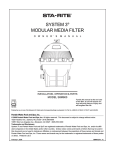
1
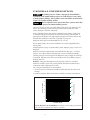
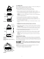
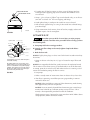
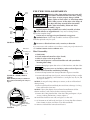
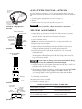
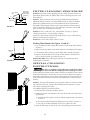
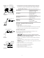
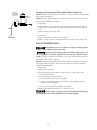
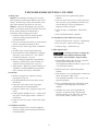
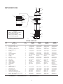
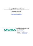
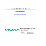
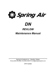
POSI-FLO® II FILTERS
O
W
N
E
R’
S
M
A
N
U
A
L
INSTALLATION, OPERATION & PARTS
MODELS
PTM50
PTM70
PTM100
PTM135
Furnish this manual to the end user of
this filter; its use will reduce service
calls and chance of injury and will
lengthen filter life.
Pentair Water Pool and Spa, Inc.
1620 Hawkins Ave., Sanford, NC 27330 • (800) 831-7133 • (919) 566-8000
10951 West Los Angeles Ave., Moorpark, CA 93021 • (800) 831-7133 • (805) 553-5000
Visit us on the Internet @ www.pentairpool.com or www.staritepool.com
© 2009 Pentair Water Pool and Spa, Inc.
S294 (Rev. A 4/16/09)
STA-RITE POSI-FLO II FILTERS:
®
To avoid unneeded service calls, prevent possible injuries, and get the most
out of your filter, READ THIS MANUAL CAREFULLY!
The Sta-Rite Posi-Flo® II Series Filter:
•Is designed to filter water for swimming pools, spas and hot tubs.
•Is an excellent performer; durable, reliable.
Table of Contents
Safety Instructions .......................................................................................3
General Information ....................................................................................4
Installation - General...................................................................................5
Installation - Assembling Filter..................................................................6-7
Startup ........................................................................................................7
Filter Disassembly/Assembly ....................................................................8-9
Filter Cleaning Procedure ..........................................................................10
Special Cleaning Instructions................................................................10-11
Pool Maintenance ................................................................................11-12
Winterizing ...............................................................................................12
Troubleshooting Guide..............................................................................13
Repair Parts List.........................................................................................14
Before installing, open filter to make sure internal air
bleed tube and air bleed filter (Key Nos. 13 and 14,
Page 14) are in place. Clean air bleed periodically.
2
READ AND FOLLOW SAFETY
INSTRUCTIONS!
This is the safety alert symbol. When you see this symbol on your system
or in this manual, look for one of the following signal words and be alert
to the potential for personal injury.
warns about hazards that will cause death, serious personal
injury, or major property damage if ignored.
warns about hazards that can cause death, serious personal
injury, or major property damage if ignored.
warns about hazards that will or can cause minor personal injury
or property damage if ignored.
NOTICE indicates special instructions not related to hazards.
Carefully read and follow all safety instructions in this manual and on equipment. Keep safety labels in good condition; replace if missing or damaged.
Component Checklist
(See Page 14)
The carton should contain the
following:
Filter Assembly
Pressure Gauge
Air Release Valve Assembly
Pressure Gauge Screen
If not, please contact Customer
Service at 1-800-831-7133.
Incorrectly installed or tested equipment may fail, causing
severe injury or property damage. Have a trained pool professional perform all pressure tests. Read and follow instructions in
owner's manual when installing and operating equipment.
1. Do not connect system to a high pressure or city water system.
2. Use equipment only in a pool or spa installation.
3. Trapped air in system can cause explosion. BE SURE all air is out of system
before operating or testing equipment.
Before pressure testing, make the following safety checks:
• Check all clamps, bolts, lids, and system accessories before testing.
• Release all air in system before testing.
• Tighten Sta-Rite trap lids to 30 ft. lbs. (4.1 kg-cm) torque for testing.
• Water pressure for test must be less than 25 PSI (172 kPa).
• Water Temperature for test must be less than 100o F. (38o C).
• Limit test to 24 hours. After test, visually check system to be sure it is ready
for operation. Remove trap lid and retighten hand tight only.
NOTICE: These parameters apply to Sta-Rite equipment only. For
non-Sta-Rite equipment, consult manufacturer.
BEFORE WORKING
ON FILTER:
If filter clamp is
adjusted under pressure, tank will blow
off of base, causing
severe injury or major
property damage.
3
1. Stop pump.
2. Open air release
valve.
3. Release all pressure
from system.
GENERAL INFORMATION
Hazardous pressure. If filter is improperly disassembled or assembled, it will explode under pressure. To avoid danger of severe injury
or major property damage, always follow service instructions in this manual
(Pages 8 to 10) when working on filter.
Risk of explosion. Never operate this filter system at more than
50 pounds per square inch (50 PSI/345kPa) pressure!
Clean a new pool as well as possible before filling pool and operating filter.
Excess dirt and large particles of foreign matter in the system can cause
serious damage to the filter and pump.
With a cartridge filter system in place and operating correctly, clean water
is returned to the pool faster than the pool water is being contaminated. A
typical pool installation will require approximately one week to obtain and
maintain the sparkle that your filter is capable of giving you.
Keep pool water pH at recommended level (7.2 to 7.6).
Be sure both clamps are in place and knobs are securely tightened before
starting filter.
Maintain pressure gauge in good working order. Replace gauge if it fails or is
damaged.
Make sure internal air bleed tube and air bleed filter (Key Nos. 13 and 14,
Page 14) are in place before operating filter. Clean air bleed periodically.
Cleaning interval is based on pressure differential, not on length of time filter
is operated. Different areas and water conditions will have different normal
cleaning intervals.
NOTICE: Some pool disinfectants may clog filter media. To maximize
media life and filter cycle time, closely follow disinfectant manufacturer’s
instructions when cleaning pool or filter.
On a new pool installation, we recommend:
1. Turn to Page 8 for instructions and disassemble the filter after the initial
cleanup.
2. Remove and hose down the element assembly to remove contaminants.
24
55.0
45.0
16
35.0
12
25.0
8
15.0
Pressure Drop (Feet)
Pressure Drop (PSI)
20
4
5.0
0
0
20
40
100
60
80
Flow Rate (G.P.M.)
120
140
577 0993
Pressure drop curve for all PTM filters. Find flow on chart and go up until line
intersects curve to find pressure drop for your filter.
4
INSTALLATION - GENERAL
Installation of filter should only be done by qualified, licensed personnel.
Filter mount must
Provide space and lighting for easy access for routine maintenance.
Provide adequate ventilation and drainage for pump.
Be protected from weather and reasonably level.
Be less than three feet above pool water level.
Be as close to pool as possible to reduce line loss from pipe friction.
Piping
All piping must conform to local and state plumbing and sanitary codes.
Never use pipe joint sealing compound on pipe and fittings that are plastic or
may come into contact with plastic. To seal threaded connections on PVC
pipe and fittings, use only Teflon® tape, Plasto-Joint Stik® or Silastic 732® RTV;
pipe joint compound may cause stress cracking of plastic components. Use
pipe joint compounds only on metal-to-metal joints.
Support pipe independently to prevent strains on filter or pump.
Use 1-1/2” or 2” pipe to reduce pressure losses.
Before installing,
open filter to make
sure internal air
bleed tube and air
bleed filter (Key
Nos. 13 and 14,
Page 14) are in
place. Clean air
bleed periodically.
WARNING
NOTICE: Filter locations remote from pool are possible but may require larger
pipe to produce adequate flow through filter.
Check local codes if considering a remote installation.
Fittings restrict flow; for best efficiency use fewest possible fittings.
Keep piping tight and free of leaks: pump suction line leaks may cause
trapped air in filter tank or loss of prime at pump; pump discharge line leaks
may show up as dampness or jets of water.
Valves
A check valve installed between pool and filter outlet will prevent
contaminants from draining back into pool.
NOTICE: A check valve between filter and pool will also prevent possible
backflow which could dislocate element from its seat.
Upper
Arm
ForeArm
Head
Bod
y
Le
g
Jo
A check valve installed between filter and heater will prevent hot water from
heater from backing up into the filter and deforming filter elements.
int
Head
Leg Joint
Joi
nt
Leg
NOTICE: Damaging filter elements through excessive heat voids the warranty.
Bod
y
Electrical
Risk of drowning and
falls. Place equipment
at least 4 feet from pool
so that children cannot
climb
over it into pool.
sss
Do not allow children
to stand or play on filter
or pump.
BE SURE filter grounding and bonding meets local and National Electrical
Code standards. All wiring, grounding and bonding of associated equipment
must meet local and National Electrical Code standards.
5
Assembling Filter
Tank
Head
Filter cartridge may shift position during shipping. To make sure cartridge is in
place, follow procedure below before using filter.
When disassembling filter, place all parts in a clean area.
1. Place filter in a clean area near its permanent location.
2. Remove Clamp Fastener from clamp indicated in Figures 1 and 2.
Set
Clamp
On Base
Clamp
Lower
Tank
Body
3. Loosen indicated clamp (see Figures 1A and 1B); remove clamp by lifting
straight up over tank or dropping it onto filter base (See Figures 1, 2,
and 3).
NOTICE: Do not pull clamp sideways to remove; to do so will bend and
damage clamp (See Figure 3).
4. Remove tank head from filter. BE CAREFUL not to damage O-Ring.
5. Set tank head in a clean place; check for missing or damaged parts.
6. Filter element should be installed with blue end up (marked `TOP’) and
red end firmly pressed into base.
Base
149 0993
7. Be sure air tube filter is seated on top of air bleed tube and tube is seated
in base.
FIGURE 1 – PTM135
Tank Head
Lift clamp over
and off
of filter
Clamp
OR
Filter
Tank
Set clamp
on base.
Base
8. Replace tank head evenly on filter tank shell for a tight seal.
NOTICE: Be sure O-Ring and O-Ring seating area are clean.
9. Place clamp assembly over flange of tank head and tank body and tighten
with clamp knob.
NOTICE: To properly engage tank head and tank body flange with clamp,
you may have to push down on top of tank head while installing clamp.
10. Tighten clamp firmly hand tight; tap clamp around tank with rubber
hammer while tightening to aid sealing.
11. Attach pressure gauge and air release valve as shown in Figure 4. Apply
Teflon tape, Plasto-Joint Stik or Silastic RTV#732 to threads of pressure
gauge.
NOTICE: Tighten gauge hand tight only. Tighten air release valve finger
tight only.
Connecting Filter Piping
FIGURE 2 – PTM50, PTM70900
&0594
PTM100
NOTE: DO NOT pull clamp off outward
(sideways) from filter. It will bend and damage
the clamp.
NOTICE: For ease of installation, plastic pipe and fittings are recommended
for all piping to and from pool. DO NOT use pipe joint compound on base of
filter; to do so will cause stress cracking of base, which will void warranty and
may cause property damage.
Risk of damage to filter. Do not tighten fittings into base ports
past thread stops. To do so will ruin filter base and void warranty, and may
cause property damage.
NOTICE: If pool or spa/tub water level is higher than filter base, shut-off
valves must be installed in suction and return lines.
FILTER
1. See Figure 5 for piping connections to filter.
CLAMP
Do not pull
clamp outward
from filter
802 0394
FIGURE 3
6
PRESSURE GAUGE
AIR RELEASE VALVE
2. To make sure all filter base ports are clear, screw all fittings into base
hand tight before applying pipe sealer to threads. BE CAREFUL not to
cross thread.
3. Wrap 1-1/2 to 2 layers of Teflon® tape to male threads only, or use PlastoJoint Stik® or Silastic 732® RTV on all piping and fittings.
4. Hand tighten fitting in each port. Be careful not to cross thread.
5. With wrench, tighten fittings to a snug fit. Be careful not to thread fittings
past thread stop.
804 0394
START-UP
FIGURE 4
Top View of Filter
6. If pipe connections leak, remove, clean off sealant, reapply sealant and
retighten in ports. Do not overtighten.
Hazardous pressure. Risk of severe injury or major property
damage if tank explodes. Read the entire procedure before starting system or
disassembling filter.
From Pump Discharge
#1 Inlet Port
Aiir Release Valve
Filter Tank
A. Turn pump OFF before starting procedure.
#4 Auxiliary
Drain Port
#2 Outlet Port
Valve
Return Line to Pool
or Spa/Hot Tub
Filter Base
Clamp Assembly
B. Properly seat filter clamps and securely tighten clamp knobs before
proceeding.
C. Read decal on tank.
#3 Tank Drain Port
Valve
945 0594
Garden Hose
Pressure Gauge
# 3 tank drain port is used to drain tank prior to
normal filter cleaning.
#4 auxiliary drain port is used to drain excess
unfiltered water (e.g., from heavy rainfall, etc.) to
waste or to drain filter if a heavy dirt load plugs
cartridge. Three-quarter inch hose bibs may be
fitted to these drains to allow easy drainage of
waste water away from filter area.
FIGURE 5
NOTICE: Tightly close plugs or valves in #3 Tank Drain Port and #4 Auxiliary
Drain Port.
1. Open air release valve (Key No. 2, Page 14) located on top of filter tank
head.
NOTICE: Air trapped inside the filter greatly increases the explosion hazard.
The air release valve allows you to get accumulated air out of the filter tank.
At startup, open the air release valve and make sure that it is running a solid
stream of water before putting the filter in service.
2. Start pump.
3. When a steady stream of water comes from air release valve, close valve.
4. After filter is operating, record filter pressure gauge reading in owner’s
manual for future use.
NOTICE: When installed on a new pool, filter element may need cleaning
after approximately 48 hours of operation.
NOTICE: A new or recently cleaned filter element may pass some foreign
material until it builds up a sufficient coating to stop all “fines”. This is
normal; a short operational period will correct the condition.
Check pressure gauge; if pressure has risen more than 10 PSI (70kPa) above
startup pressure, remove and clean element.
7
Tank
Head
FILTER DISASSEMBLY
Hazardous pressure.
Clamp
Set
Clamp
On Base
Lower
Tank
Body
Base
149 0993
Releasing either clamp with pressure on system will
cause tank or tank head to blow off of base, causing
severe injury or major property damage. NEVER
adjust, tighten or loosen either “V” band clamp when
tank is under pressure. If filter leaks at the clamp, do
not adjust the clamp. Instead, follow instructions
under “Filter Disassembly”, below and “Filter
Assembly”, Page 9.
Regularly inspect clamp assemblies for cracked, corroded, or broken
welds and worn or stripped threads. If any wear or damage shows,
replace the complete clamp.
Tension stresses and aggressive pool chemicals can aggravate
mechanical wear. Tank clamp assemblies and nuts or plastic knobs
should be replaced every five years.
FIGURE 6A – PTM135
Do not use a filter that shows cracks, corrosion, or distortion.
Tank Head
Lift clamp over
and off
of filter
If you are unsure of the condition of your filter, consult your pool professional or
call: Sta-Rite Customer Service 1-800-831-7133.
Filter Disassembly:
1. STOP PUMP.
2. CLOSE suction and return line valves (if used).
Clamp
3. OPEN air release valve on top of filter.
OR
Filter
Tank
4. WAIT until all pressure is released from filter tank and system before
loosening either clamp.
5. Remove drain plug or open drain valve at `Tank Drain Port’ and drain filter.
Set clamp
on base.
Base
To prevent severe or fatal injury, make sure that all pressure
has been released from filter tank before proceeding.
6. Remove clamp fastener from clamp indicated in Figures 6A and 6B.
900 0594
FIGURE 6B – PTM50, PTM70 &
PTM100
NOTE: DO NOT pull clamp off outward from
filter. It will bend and damage the clamp. See
Figure 7.
7. Loosen indicated clamp (see Figure 6); remove clamp by lifting it straight
up over tank or dropping it onto filter base. (see Figures 6A, 6B, 7A, and
7B, Pages 8 and 9).
NOTICE: Do not pull clamp sideways to remove; to do so will bend and
damage clamp.
8. Remove tank head from tank body. Be careful not to damage “O” Ring.
Place tank head in clean area.
NOTICE: If heavy dirt deposits have collected around bottom of filter
element and base, wash out base before removing element.
9. Remove the O-Ring from the filter. Clean the O-Ring and inspect it. If you
see cuts, cracking, deformation, or wear, replace it.
FILTER
CLAMP
Do not pull
clamp outward
from filter
10. Rock filter element to one side (see Figure 8) to free seal.
11. Lift element out of tank body (See Figure 9). Do not drop filter element.
Place element in clean area where it can be hosed down.
12. Remove air bleed filter from tube and clean it.
802 0394
FIGURE 7A
8
ADAPTER INSTALLATION
Discard clamp if
it is bent or
twisted
Final gap
should be
1/4-3/8"
Discard clamp if
rivets are corroded
or cracked or welds
are broken
Use PVC cement to attach a 1-1/2” PVC socket-to-thread adapter (not supplied) to raised collar on filter base to allow attachment of an elbow and hose
for:
1. vacuuming pool, putting water to waste (see Page 12);
2. draining;
Discard clamp
if threads of
bolt, nut, or knob
are stripped or worn
3. lowering water level in pool or spa/tub (see Figure 17).
2030 0995
Flammable and poisonous fumes. Use cement only in a well
ventilated area away from flame; follow manufacturer’s instructions.
FIGURE 7B – Clamp Inpection
Procedure
FILTER ASSEMBLY
Air Bleed Tube Filter
Air Bleed Tube
1. Replace plugs or close valves in Tank Drain and Auxiliary Drain ports.
2. Push clean air bleed filter all the way down on tube. If tube has been
removed, push it into socket seat in base until it bottoms.
Move Filter
Element to one
side to Break
Bottom Seal
3. Set filter element on base.
Filter
Element
Bottom
Seal Ring
Filter
Base
NOTICE: Be sure blue end marked “TOP” is on top and red end is on
bottom. Do not reverse element.
4. Push filter element into base between two circular ribs until it bottoms.
5. Inspect and clean the tank flanges and upper and lower O-Ring seats. If
flanges are deformed, cracked, or corroded, replace entire filter.
6. Reinstall O-Ring. Reinstall tank head. See below for a list of approved
O-Ring lubricants.
NOTICE: On multiple-clamp units, clamp/O-Ring sets are not
interchangeable. When replacing more than one clamp, refer to Parts List,
Page 14, for correct location.
574 0993
FIGURE 8
LIFT FILTER ELEMENT
STRAIGHT UPWARD
TO REMOVE
Do not remove or damage safety and instruction labels during
cleaning. Replace any decals which may have been damaged.
7. If bottom clamp was removed, BE SURE bottom of tank body is clean; set
tank body evenly on base and “O” Ring.
8. Install clamp(s) and knob assembly(s); Tighten clamps equipped with knobs
firmly hand tight. Tighten clamps equipped with nuts to 20-30 in. lbs.
(23-35 cm-kg) torque. The final gap between the clamp ends should be
1/4 to 3/8” (6 to 9.5 mm).
Filter Base
9. Clean pump strainer basket.
10. Open system valves as needed.
803 0294
11. Proceed to “Startup”, Page 7.
FIGURE 9
STA-RITE APPROVED O-RING LUBRICANTS
1-1/2" Female
Pipe Thread
Built In
Raised Collar
1-1/2" PVC
Socket to
Female
Thread Adapter
Socket End
Filter
Base
Petroleum Jelly (Vaseline®)
Semi-Permanent Lubrication
Parker Super-O-Lube™
Semi-Permanent Lubrication
Aqua-Lube by Allube
Semi-Permanent Lubrication
5% or less Mild Soap Solution
Assembly Lubrication
®
559 0993
FIGURE 10
9
Elbow: Male
Pipe Thread
to Hose Barb
Hose Clamp
Hose
Adapter In
Place
To
Waste
Filter Base
560 0993
FIGURE 11
FILTER CLEANING PROCEDURE
NOTICE: Keep track of filter operating pressure. When pressure reaches 10
pounds per square inch (PSI) (70kPa) above initial operating pressure, clean
filter element.
NOTICE: When sanitizing your pool using PHMB (polyhexamethylene
biquanide based) sanitizers, use only PHMB cleaners to clean the module.
When using PHMB sanitizers, the filter module MUST be cleaned more
thoroughly and frequently than for a pool using chlorine. Follow manufacturer’s instructions carefully. Use of any other type of cleaners with PHMB
pool sanitizers will void the filter’s warranty.
NOTICE: If filter is used with a spa, soak element (see Step 2, “Special
Cleaning Instructions”) at each regular cleaning.
With hose, wash foreign material from inside of base. Try to avoid washing
debris into outlet port (see Figure 12).
NOTICE: Be sure inside surface of base is clean.
Washing Filter Element (See Figures 13 and 14):
1. Use a garden hose with straight flow nozzle to wash down filter element
(Figure 13).
2. Work from the top down; wash down all pleats. Wash between all pleats.
Tank Drain
Port
3. Turn element while spraying to wash down entire outside of element.
4. Repeat wash down process for inside of filter element. Hold nozzle as
close to inside of pleats as possible (Figure 14).
NOTICE: BE SURE all dirt and foreign materials are washed away from
INSIDE pleats of element.
815 0394
FIGURE 12
SPECIAL CLEANING
INSTRUCTIONS:
Risk of fire or explosion. Isolate filter from system before chemical cleaning; rinse filter and elements completely before returning to service.
If filter cannot be isolated, remove media and clean at another location. Follow
chemical manufacturer’s instructions for use. Do not mix chemicals except as
directed by manufacturer. Do not allow cleaning chemicals to mix with or to
come in contact with chlorine, bromines, other chemicals, or chemical feed
devices.
NOTICE: Some pool disinfectants may clog filter media. To maximize media
life and filter cycle time, closely follow disinfectant manufacturer’s instructions when cleaning pool or filter.
For stubborn deposits, proceed as follows:
055 0893
FIGURE 13
1. Follow Regular Cleaning Procedure (above).
056 0893
FIGURE 14
2. If deposits remain, soak element at least one hour with one of the following solutions:
A. Commercial filter cleaner (see chart: follow manufacturer’s instructions
for use), or
B. One cup automatic dishwasher detergent to five gallons of water, or
C. One cup Tri Sodium Phosphate (TSP) to five gallons of water.
3. Wash off with water to remove oils, dirt and remaining cleaner solution.
10
Circular Rib or Outer Circular Rib or
Outer Seal Ring.
Seal Ring
O-Ring
Sealing Area
Filter Element
4. If filter element does not come clean with this procedure, consult your
pool professional. Acid washing should be done only by trained professionals who have proper safety equipment and acid disposal facilities.
Specialty Filter Cleaners (for Degreasing and Scale Removal)
Filter Cleanse™
Great Lakes Biochemical Co.
1400 Bluegrass Lakes, Pkwy.
Alpharetta, GA 30004
Filter Kleen™
Haviland Products Co.
421 Ann St. NW.
Grand Rapids, MI 49504
Spa Instant Cartridge Clean™ or
Filter Clean™
Leisure Time Chemical Corp.
1620 Proforma Ave.
Ontario, CA 91761
KleenIt™ or
Strip-Kwik®
Biolab Inc.
P.O. Box 300002
Lawrenceville, GA 30049
Base
949 0594
FIGURE 15
Vacuum to Waste Cycle
947 0594
POOL MAINTENANCE
Vacuum Cycle:
FIGURE 16
1. Attach vacuum hose to skimmer connection.
2. Adjust suction line valves to provide sufficient flow through vacuum tube.
3. Proceed to vacuum. Filtered water will be recirculated back to pool.
Lowering or Draining Pool
Vacuum to Waste Cycle:
If dirt load in pool has built up to the point that vacuuming to waste
(bypassing filter) is desirable, proceed as follows:
948 0894
1. Disassemble filter.
Hazardous pressure. Filter may explode if incorrectly
disassembled. To avoid severe injury or major property damage, exactly
follow instructions under “Disassembly” (Page 8)!
FIGURE 17
Hose Clamp
Hose
To
Waste
Elbow: Male
Pipe Thread
to Hose Barb
Adapter In
Place
Filter Base
560 0993
2. Thread a 1-1/2” 90 degree PVC elbow into female adapter on filter base
(see Figure 18).
3. Attach hose to elbow as shown in Figure 18; run hose to waste water
disposal area.
NOTICE: Be sure all waste water disposal meets applicable local and state
standards and codes.
4. Make sure Tank Drain Port is closed or plugged.
5. Adjust valves on suction pipe for vacuum operation.
6. Attach vacuum hose to skimmer connection.
7. Start filter pump; vacuum pool.
8. Adapter can be left on collar for future cleaning.
FIGURE 18
11
Draining or Lowering Pool Through Auxiliary Drain Port
Lowering or
Draining Pool
Using Auxiliary
Drain Port.
Auxiliary
Drain Port
950 0594
FIGURE 19
NOTICE: When using “Auxiliary Drain Port” it is not necessary to disassemble
filter or remove element.
NOTICE: If pool is being drained, use main drain only. Be sure to close valve
in suction pipe leading to skimmers.
1. Stop pump.
2. Attach garden hose or drain hose to Auxiliary Drain Port (see Figure 19).
Position hose so that water runs away from pool to wastewater disposal
area.
3. Open Auxiliary Drain Port valve.
4. Start pump.
5. Open air release valve (Key No. 2, Page 14).
6. When a steady stream of water flows from air release valve, close valve.
WINTERIZING
Hazardous pressure. To avoid severe injury or major property
damage, exactly follow instructions below.
Explosion hazard. Purging the system with compressed air can
cause components to explode, with risk of severe injury or death to anyone
nearby. Use only a low pressure (below 5 PSI), high volume blower when air
purging the pump, filter, or piping.
NOTICE: Filter must be protected from the weather and drained if freezing is
anticipated. Allowing filter to freeze can cause damage to filter and WILL
VOID THE WARRANTY!
1. Stop pump.
2. Open air release valve.
3. Remove drain plugs from ports or open valves at “Tank Drain” and
“Auxiliary Drain Ports”.
4. Drain ALL piping to and from filter.
A. Gravity drain system as far as possible.
B. Protect areas which retain water with non-toxic propylene glycol
antifreeze (“RV antifreeze”).
5. Turn to Page 8 for filter disassembly instructions.
6. Remove filter element and store in a warm, dry area.
Do not remove or damage safety and instruction labels during
cleaning. Replace any decals which may have been damaged.
12
TROUBLESHOOTING GUIDE
A. Short Cycle:
2. Element cloth torn or punctured; replace
element.
NOTICE: Time between cleanings will vary with
each installation and between different areas of the
country. The following causes and remedies are for
cycle times shorter than normal for your area.
3. Filter too small, flow too low, or daily operating
time too short, giving inadequate turnover rate;
consult dealer to verify that equipment is
properly sized for your pool.
NOTICE: Some pool disinfectants may clog filter
media. To maximize media life and filter cycle time,
closely follow disinfectant manufacturer’s
instructions when cleaning pool or filter.
1. Chlorine residual too low; maintain proper
residual (consult pool professional for
recommendation).
2. Flow rate too high; restrict flow to rated capacity
of filter (see instruction decal on filter).
3. Filter too small; install larger filter or additional
filter.
4. Pump too large - overpumping - reduce flow
rate.
5. Filter installed backward - replumb.
D. Long Recovery Time After Heavy Usage:
1. Residual Chlorine level is too low - add chlorine.
2. Filter too small - replace with larger unit.
3. Pump too large - reduce flow rate.
E. Filter Bypasses Dirt:
4. Unstable water; consult pool professional.
5. Filter element not cleaned properly or plugged
with algae, iron, calcium, etc. - see “Special
Cleaning Instructions”, Page 10.
6. Heavy or improper application of powdered
chlorine or chlorine pills using a binder; see
“Special Cleaning Instructions”, Page 10.
7. Algae in pool - Apply heavy dose of chlorine or
algaecide as recommended by pool manufacturer. Continue until algae is controlled.
To avoid severe injury or major property damage, exactly follow instructions under
“Disassembly” and “Assembly” (Pages 8 and 9)!
1. Air bleed tube and/or tube filter not in position.
Exactly follow instructions in “Filter
Disassembly/Assembly Procedure”, Pages 8 and
9, and reinstall correctly.
2. Element cloth torn or punctured; replace
element.
B. Low flow:
1. Element is plugged; see “Special Cleaning
Instructions”, Page 10.
2. Pipe blocked downstream from filter; remove
obstruction.
3. Piping too small; replace with larger pipe
(consult dealer for recommendation).
4. Pump hair and lint trap is plugged - empty and
clean.
5. Pump impeller and diffuser worn - replace with
new parts. Consult pump owner’s manual for
information.
3. Filter element is not seated properly in filter base;
follow instructions under “Filter
Disassembly/Reassembly”, Pages 8 and 9, and
reposition properly.
4. Filter is plumbed backwards and element cloth
is ruptured - replumb properly and replace
element.
5. Colloidal fines (very small suspended dirt
particles) are present and passing through
element covering. Floc with alum, or if fines
have already settled, vacuum to waste.
6. Pump too small for system - replace with larger
pump.
C. Pool Water Not Clear:
1. Chlorine dosage too low; maintain adequate
chlorine residual (consult pool professional for
recommendation).
13
1
EXPLODED VIEW
2
2A
3
4
12
5
4
16
15
5
14
13
17
6
7
NOTICE:
O-Rings, key numbers 4 and 7,
are not interchangeable.
Clamps, key numbers 5 and 9,
are not interchangeable.
12
8
9
11
10
162 1193
REPAIR PARTS LIST
Key
No.
1
2
2A
3
4
5
6
7
8
9
10
11
12
13
14
15
16
17
•
•
•
•
•
•
•
Part
Description
No.
Used
Pressure Gauge
Air Release Valve Ass’y
O-Ring
Lid Ass’y (Includes Nos. 1,
1A, 2, and decals)
O-Ring *
Clamp*
Lower Tank Body
Filter Element
O-Ring
Clamp
Base w/Pipe Plugs
Pipe Plug
Clamp Nut*
Air Bleed Tube
Air Bleed Filter
Clamp Knob
Plug
Upper Tank Body
Model Decal
Warning Decal
Instruction Decal
Clamp Hazard Decal**
Air Release Warning Decal**
Decal: “DO NOT USE PIPE DOPE”
Decal: “Top Clamp”
•Not Illustrated
Model
PTM50
Model
PTM70
Model
PTM100
Model
PTM135
1
1
1
1
15060-0000T
25010-0200
U9-359
25010-9201
15060-0000T
25010-0200
U9-359
25010-9201
15060-0000T
25010-0200
U9-359
25010-9202
15060-0000T
25010-0200
U9-359
25010-9201
1
1
1
1
1
1
1
2
1
1
1
1
1
1
1
1
1
1
2
1
1
31935-0001
25010-9101
25010-0001
WC108-56S2X
WC9-3
25010-9100
WC104-78P
WC78-38T
WC36-1
25010-0007
WC8-35
WC36-22
––
––
32155-4040
32155-4049
32155-4075
WC27-19
WC27-23
WC27-27
32165-4036
31935-0001
25010-9101
25010-0001
WC108-57S2X
WC9-3
25010-9100
WC104-78P
WC78-38T
WC36-1
25010-0007
WC8-35
WC36-22
––
––
32155-4041
32155-4049
32155-4075
WC27-19
WC27-23
WC27-27
32165-4036
31935-0001
25010-9101
25010-0001
WC108-58S2X
WC9-3
25010-9100
WC104-78P
WC78-38T
WC36-1
25010-0008
WC8-35
WC36-22
––
––
32155-4042
32155-4049
32155-4075
WC27-19
WC27-23
WC27-27
32165-4036
31935-0001
25010-9101
25010-0001
WC108-70S2X
WC9-3
25010-9100
WC104-78P
WC78-38T
WC36-1
25010-0010
WC8-35
WC36-22
36305-4032T
25005-0001
32155-4066
32155-4049
32155-4075
WC27-19
WC27-23
WC27-27
32165-4036
* Model PTM135 uses 2
** Model PTM135 uses 3.
14
This page is blank.
15
© 2009 Pentair Water Pool and Spa, Inc. All rights reserved.
This document is subject to change without notice.
1620 Hawkins Ave., Sanford, NC 27330 • (800) 831-7133 • (919) 566-8000
10951 West Los Angeles Ave., Moorpark, CA 93021 • (800) 831-7133 • (805) 553-5000
Trademarks and Disclaimers: Posi-Flo® and Sta-Rite® are trademarks and/or registered trademarks of Pentair Water Pool and Spa, Inc. and/or its affiliated companies
in the United States and/or other counties. Plasto-Joint Stik® is a registered trademark of La-Co Industries, Inc., Teflon® is a registered trademark of E.I. Du Pont De
Nemours and Company Corporation, Silastic 732® is a registered trademark of Dow Corning Corporation, Vaseline® is a registered trademark of Unilever Supply
Chain, Inc., Parker Super O-Lube™ is a trademark of Parker Hannifin Corp., Aqua-Lube® is a registered trademark of Tifco Industries, Inc., Filter Cleanse™ is a
trademark of Advantis Technologies, Inc., Strip-Kwik® and KleenIt™ are trademarks and/or registered trademarks of Bio-Lab, Inc., Filter Kleen™ is a trademark of Haviland
Consumer Products, Inc., Spa Instant Cartridge Clean™ and Filter Clean™ are trademarks of Leisure Time Chemical Corp. Unless noted, names and brands of others
that may be used in this document are not used to indicate an affiliation or endorsement between the proprietors of these names and brands and Pentair Water Pool and
Spa, Inc. Those names and brands may be the trademarks or registered trademarks of those parties or others.
S294 (Rev. A 4/16/09)