1
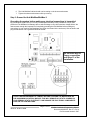
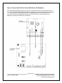
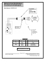
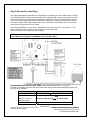
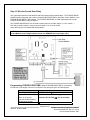
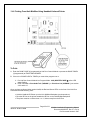
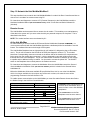
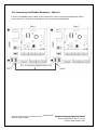
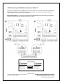
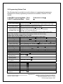
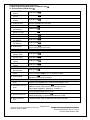
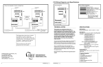
IEI Hub MiniMax/MiniMax II Installation/Programming Manual Document Number: 6055037, Rev. 3.3 Manual Revision Date: 3/2/05 Hub MiniMax Firmware Revision: U2: 1.0p, U10: 1.1F Hub MiniMax II Firmware Revision: U2: 2.0a, U10: 2.3b Fax Document Number: 5037 Page 1 of 52 www.ieib.com MiniMax Installation/Programming Manual Document # 6055037, Rev. 3.3, D11b Fax Document Number: 5037 1.0 SYSTEM FEATURES AND SPECIFICATIONS........................................................ 4 1.1 SYSTEM FEATURES...................................................................................................... 4 1.2 SPECIFICATIONS .......................................................................................................... 4 1.3 SYSTEM DEFAULTS ...................................................................................................... 5 1.4 HUB DOOR CONTROL MODULE DIAGRAM ...................................................................... 5 1.5 HUB MINIMAX/MINIMAX II BACKPLANE DIAGRAM .......................................................... 6 2.0 UL REQUIREMENTS................................................................................................ 7 2.1 TAMPER REQUIREMENTS .............................................................................................. 7 2.2 POWER AND NON-POWER LIMITED WIRING.................................................................... 8 2.3 LITHIUM BATTERY REPLACEMENT ................................................................................. 9 3.0 INSTALLATION ...................................................................................................... 10 STEP 1: UNPACK THE HUB MINIMAX/MINIMAX II AND CHECK THE PACKING LIST................. 10 STEP 2: MOUNT THE HUB MINIMAX/MINIMAX II ENCLOSURE .............................................. 10 STEP 3: GROUND THE HUB MINIMAX/MINIMAX II............................................................... 11 STEP 4: CONNECT THE HUB DOOR CONTROL MODULE TO THE BACKPLANE ........................ 12 STEP 5: WIRE AN ELECTRIC DOOR LOCK TO THE MAIN RELAY OF THE HUB DOOR CONTROL MODULE ......................................................................................................................... 13 5A: LOCK OUTPUT .......................................................................................................... 14 5B: AUXILIARY OUTPUT................................................................................................... 14 STEP 6: CONNECT A FRONT END READER TO THE HUB DOOR CONTROL MODULE ............... 15 STEP 7: WIRE A REQUEST TO EXIT (REX) DEVICE AND DOOR CONTACT TO THE HUB DOOR CONTROL MODULE .......................................................................................................... 20 STEP 8: WIRE THE ALARM SHUNT RELAY ......................................................................... 21 STEP 9: WIRE THE DOOR AJAR RELAY ............................................................................. 22 STEP 10: WIRE THE FORCED DOOR RELAY ....................................................................... 23 STEP 11: CONFIGURE THE HUB MINIMAX/MINIMAX II TO PRINT .......................................... 24 11A: PRINTING FROM HUB MINIMAX USING HANDHELD INFRARED PRINTER ....................... 25 11B: CONNECTING A SERIAL LINE PRINTER TO THE HUB MINIMAX/MINIMAX II BACKPLANE. 26 STEP 12: NETWORK THE HUB MINIMAX/MINIMAX II........................................................... 28 12A: NETWORKING HUB MINIMAX BACKPLANES - METHOD 1 ........................................... 30 12B: NETWORKING HUB MINIMAX BACKPLANES - METHOD 2 ............................................ 31 12C: NETWORKING HUB MINIMAX TO HUBPLUS KIT - METHOD 1....................................... 32 12D: NETWORKING HUB MINIMAX TO HUBPLUS KIT - METHOD 2....................................... 33 STEP 13: COMPLETE CONNECTIONS BETWEEN THE 16.5 VAC TRANSFORMER AND HUB MINIMAX......................................................................................................................... 34 STEP 14: POWER UP THE SYSTEM .................................................................................... 35 TROUBLESHOOTING ......................................................................................................... 35 Page 2 of 52 www.ieib.com MiniMax Installation/Programming Manual Document # 6055037, Rev. 3.3, D11b Fax Document Number: 5037 4.0 PROGRAMMING THE HUB MINIMAX/MINIMAX II ............................................... 36 4.1 PROGRAMMING METHODS .......................................................................................... 36 4.2 PROGRAMMING FEATURES ......................................................................................... 37 4.3 SENDING INFORMATION BETWEEN NETWORKED HUB DOOR CONTROLLERS .................. 38 4.4 PRINTING THE TRANSACTION LOG AND USER LIST ....................................................... 40 4.4.1 SELECTING THE PRINTING OUTPUT PORT ................................................................. 40 4.4.2 SETTING THE TIME/DATE AND DOOR NUMBER .......................................................... 40 4.4.3 SETTING/MASKING EVENTS FOR LOGGING IN EVENT BUFFER ..................................... 41 4.4.4 PRINTING THE TRANSACTION LOG............................................................................ 42 4.4.5 PRINTING A USER LIST ............................................................................................ 42 4.5 PROGRAMMING DAYLIGHT SAVINGS TIME .................................................................... 43 5.0 PROGRAMMING OPTIONS CHART...................................................................... 44 6.0 DEFINITIONS OF TERMS AND HUB MINIMAX FUNCTIONS .............................. 47 7.0 WARRANTY AND RETURN INFORMATION ........................................................ 49 7.1 WARRANTY ............................................................................................................... 49 7.2 CUSTOMER SERVICE POLICY ...................................................................................... 49 7.3 RETURNS POLICY ...................................................................................................... 49 7.4 30-DAY OUT OF BOX EXCHANGE ............................................................................... 49 7.5 TECHNICAL SUPPORT ASSISTED IN-WARRANTY PRODUCT DEFECTS ............................. 50 7.6 NON TECHNICAL SUPPORT ASSISTED IN-WARRANTY PRODUCT DEFECTS ..................... 50 7.7 STOCK ROTATION/ADJUSTMENT (IN-WARRANTY) ......................................................... 50 7.8 RE-BOX OR REWORK (IN-WARRANTY) ......................................................................... 50 7.9 REPAIR/REPLACEMENT POLICY .................................................................................. 50 7.10 REPAIR ................................................................................................................... 50 7.11 REPLACEMENT ........................................................................................................ 51 Page 3 of 52 www.ieib.com MiniMax Installation/Programming Manual Document # 6055037, Rev. 3.3, D11b Fax Document Number: 5037 1.0 System Features and Specifications The following section outlines the Hub MiniMax/MiniMax II features, specifications and default settings. 1.1 System Features Feature Users Base Capacity Additional Capability Description/Details 500 (Hub MiniMax); 2000 (Hub MiniMax II) Supports 1 Hub Door Control Module; Controls 1 Door Network up to 32 doors with additional Secured Series Door Control Products 1000 Transaction Buffered Audit Trail (Hub MiniMax); 1500 Transaction Audit Trail Buffered Audit Trail (Hub MiniMax II) The Hub Door Control Module supports two front end readers for IN/OUT Front End Support operation. Programming Hub Door Control Module support keypad or PC programming 9:00 A.M. to 5:00 P.M. Monday-Friday Auto-Unlock Time Zones *Eight user definable time zones for auto-unlock or access control *Sixteen holiday time zones First-In Auto-Unlock Requires valid entry to initiate auto-unlock schedule. *Remote accessible via modem Forced Door Alarm Relay/Timer Alarm Zone Shunting Relay Timed Egress Input Non-Volatile EEPROM Memory * Indicates a feature is only available using software. 1.2 Specifications Electrical Power Supply Current Requirements Front End Aux Output Lock Output Main Relay Alarm Shunt, Door Ajar and Forced Door Relays REX/Door Loop Mechanical Hub MiniMax Enclosure Height Width Length Material Environmental Temperature Tolerance Recommended Use 16.5VAC 40VA or 50VA Class 2 Transformer (Revere # RT-G1640SL/M, Revere # RT-G1650SL/M or Globtek, Inc. # DA-40-16.5G) 120mA 13.8 VDC, 300mA (max. current draw) 13.8 VDC, 100mA (max. current draw) 13.8 VDC or 16.5 VAC, 600mA (max. current draw) 12-24 VAC/DC, 2A (max. contact current) 12-24VAC/DC, 1A (max. contact current) Dry contact closure Surface mount 3.56” (9.04cm) 11.29” (28.67 cm) 11.31” (28.7 cm) 19 gauge steel -20°F to 130°F (-28°C to 54°C) For indoor use only Page 4 of 52 www.ieib.com MiniMax Installation/Programming Manual Document # 6055037, Rev. 3.3, D11b Fax Document Number: 5037 1.3 System Defaults Parameter Master Code Main Relay Time Door Ajar Time Forced Door Time Printer Output Keypress Feedback Door Number First In Auto-Unlock Auto-Unlock Time Zone: (Without software) Key required to active relay after entering valid code Communication Setup Daylight Savings Time Daylight Savings Time Format Default Setting 1234 5 Seconds 30 Seconds 10 Seconds RS-232 Port Enabled 01 Off 9 A.M to 5 P.M.; Monday through Friday On Local Enabled US 1.4 Hub Door Control Module Diagram The diagram below shows the component locations and terminal connections on the Hub Door Control Module. Page 5 of 52 www.ieib.com MiniMax Installation/Programming Manual Document # 6055037, Rev. 3.3, D11b Fax Document Number: 5037 1.5 Hub MiniMax/MiniMax II Backplane Diagram The diagram below shows the component locations and terminal connections on the Hub MiniMax/MiniMax II Backplane. Page 6 of 52 www.ieib.com MiniMax Installation/Programming Manual Document # 6055037, Rev. 3.3, D11b Fax Document Number: 5037 2.0 UL Requirements The IEI Hub MiniMax and Hub MiniMax II controllers are U.L. Listed products and comply with U.L. 294. To install these products to meet U.L. requirements, all the instructions in this section and throughout this manual must be followed. The Hub MiniMax System is designed to be wall mounted (surface mounted) with the supplied hardware. The system must be installed within the protected area in accordance with the National Electrical Code (NFPA 70), local codes, and the authority having jurisdiction. It should also be located in an area that is accessible for programming purposes. After the installation is complete, the Hub MiniMax cabinet door should remain closed and locked to protect the contents. For additional information, see illustration drawing 6255037 Rev. 2.3, dated 3/2/05 located on the inside of the cabinet door. In addition, all other interconnecting devices must be U.L. Listed. A minimum of three (3) user codes must be programmed for controlling access. Note: The modem interface was not evaluated by U.L. The Panic and Duress functions also were not evaluated by U.L. The PC software is only used for downloading and uploading data. The PC does not make access control decisions or monitor the door. 2.1 Tamper Requirements To meet U.L. requirements, a U.L. Listed tamper switch must be installed in the cabinet of Hub MiniMax systems. The tamper switch must be mounted inside the locked cabinet and must activate if the cabinet door is opened. The tamper switch must be wired to an alarm panel or other device that sounds an alarm and/or prevents anyone from gaining access through the protected door. IEI recommends using a Sentrol 3012 tamper switch (not provided). To use this tamper switch, simply clip the switch on the side of the cabinet on the interior, then wire the leads to your alarm device using the appropriate U.L. type cable. See diagram below. Page 7 of 52 www.ieib.com MiniMax Installation/Programming Manual Document # 6055037, Rev. 3.3, D11b Fax Document Number: 5037 2.2 Power and Non-Power Limited Wiring To meet U.L. requirements, the Power Limited and Non-Power limited wiring must be routed away from each other and separated by a minimum of a 1/4 inch (.250"). See related descriptions and diagram below. The following terminal connections are considered Power Limited: • • • • • • • • • • Lock Output (Lock+, Lock-) Aux Output (Aux +, Aux-) Main Relay Alarm Shunt Relay Door Ajar Relay Forced Door Relay Front End Terminals REX/Door Switch Terminals Port A (RJ-11 Jack and TS1 terminal) Port C (RJ-11 Jack and TS1 terminal) The following terminal connections are considered Non-Power Limited: • • AC Transformer Input (AC, AC and EGND) Backup Battery Connection (B+ and B-) Page 8 of 52 www.ieib.com MiniMax Installation/Programming Manual Document # 6055037, Rev. 3.3, D11b Fax Document Number: 5037 2.3 Lithium Battery Replacement The lithium battery used for keeping the time and date is located on the left-hand side of the Door Control Module above the relay K2. The battery holder is labeled “BH1.” To replace the battery, first power down the module using the On/Off switch (SW1) located on the backplane. Then remove the battery carefully by lifting up the bottom edge and pull it out of the clip. Replace the battery with a Renata CR1225 or Varta CR1225 3 Volt Lithium battery. Use of another battery may present a risk of fire or explosion. WARNING: The battery may explode if mistreated. Do not recharge, disassemble, or dispose of in a fire. Page 9 of 52 www.ieib.com MiniMax Installation/Programming Manual Document # 6055037, Rev. 3.3, D11b Fax Document Number: 5037 3.0 Installation This section contains detailed unpacking and installation procedures and wiring diagrams for the IEI Hub MiniMax/MiniMax II Access Control System. This section is presented as steps and should be followed in the order indicated. Not all steps are necessary for every application. Note: Programming commands are inserted into the installation procedure for your convenience. Programming should only be done after all electrical connections are made and the system is powered up in step 13. Step 1: Unpack the Hub MiniMax/MiniMax II and Check the Packing List Open the box and inside is a metal enclosure. The metal enclosure has a removable lid, so the installer has easier access when wiring. Inside the metal enclosure is: • • • • • • • 1 Hub MiniMax Backplane mounted on standoffs in cabinet 1 16.5VAC Transformer (see section 1.2 for approved transformers) 1 Camlock with key 1 Hardware Pack containing: o 1 Wire nut (Red) o 1 Wire Nut (Orange) o 4 Wall anchors (BLUE) o 4 #8 1¼” sheet metal screws o 1 set of battery cables (BLACK AND RED) o 1 Ground Cables (BLACK wire with RED flush tab receptacle) 1 Hub Door Control Module 1 detachable keypad for programming (Pre-mounted to Hub Door Control Module) 1 Secured Series Hub MiniMax/MiniMax II Installation and Programming Manual Please check the contents of the enclosure and verify all components on the packing list are present. Taking this inventory will familiarize you with the components as well as ensure you have a complete kit. Step 2: Mount the Hub MiniMax/MiniMax II Enclosure The Hub MiniMax enclosure must be mounted on the secured side of the door and must not be used as an access device as a means of gaining access or egress through the door. Ideally the enclosure should be mounted in a secure area such as a locked utility closet. However, this is not always available so wherever you decide to mount the enclosure make sure it is accessible for programming purposes. Mounting Procedure: Unlock and open metal enclosure. Notice that the enclosure lid opens from top to bottom and if you mount the enclosure horizontally the enclosure lid will form a tabletop and a convenient workspace. You can also mount the enclosure vertically (see section 4.1). 1. Use the supplied wall anchors and sheet metal screws to secure the Hub MiniMax Cabinet to the wall. 2. Drill 11/64’’ diameter holes for the wall anchors. 3. Tap the wall anchors into the wall until the outer flange is flush to the wall surface. 4. Insert the sheet-metal screws ¾ of the way into the anchors. 5. Hang the Hub MiniMax Cabinet by aligning the slotted holes (cut into the rear of the cabinet) with the sheet-metal screws. Space between slotted holes; on-center 9-11/16” Horizontally and 10-1/8”” Vertically. Page 10 of 52 MiniMax Installation/Programming Manual Document # 6055037, Rev. 3.3, D11b Fax Document Number: 5037 www.ieib.com 6. The Hub MiniMax Cabinet should now be resting on the sheet-metal screws. 7. Tighten the sheet-metal screws until they are snug. Step 3: Ground the Hub MiniMax/MiniMax II Grounding the system before making any electrical connections is imperative! By grounding the system first you not only increase personal safety during installation, but you also protect the Hub MiniMax from damage due to static discharge or any other transient voltage effects. We cannot stress enough the importance of completely grounding the Hub MiniMax before making any connections or even touching the Backplane (the large circuit board in the enclosure). Wire as shown and plug the transformer into a grounded electrical socket. Do not make any AC Power connections until Step 13 of the installation. TOUCH THE GROUNDED METAL CABINET BEFORE TOUCHING THE BACKPLANE OR THE HUB MINIMAX CONTROL MODULE. THIS WILL REMOVE ANY STATIC CHARGE ON YOUR PERSON. STATIC ELECTRICITY CAN DAMAGE THE ELECTRONIC COMPONENTS USED ON THE CONTROLLERS. Page 11 of 52 www.ieib.com MiniMax Installation/Programming Manual Document # 6055037, Rev. 3.3, D11b Fax Document Number: 5037 Step 4: Connect the Hub Door Control Module to the Backplane The Hub MiniMax Backplane supports one Hub Door Control Module, which is provided with the unit. There are three nylon standoffs on the Backplane to support the module and a ten-pin connector labeled “J1.” On the Hub Door Control Module there is a corresponding ten-pin connector labeled “S1.” To connect the module to the Backplane, slide the S1 connector onto the J1 pin rail located on the Backplane, and snap the module onto the standoffs. Page 12 of 52 www.ieib.com MiniMax Installation/Programming Manual Document # 6055037, Rev. 3.3, D11b Fax Document Number: 5037 Step 5: Wire an electric door lock to the MAIN RELAY of the Hub Door Control Module NOTE: All locking devices must be U.L. Listed. MAIN RELAY Terminal Block NOTE: All four relays (Main, Alarm Shunt, Forced Door, Door Ajar) are FORM C DRY CONTACT, which means there is no output voltage on the relay contacts. These relays can be used on a dry contact loop or switch one leg of power to an external device as shown in the illustrations below. Lock+ and Lock- represent the Lock Output screw terminals on the backplane (TS2). If you are using AC, polarity does not matter. Please see the next section for the Lock Output details. You must use an external, U.L. Listed Access Control, Power Limited Power Supply with a minimum of four (4) hours of backup power for 24 VAC/VDC operation, or if your lock draws more than 600mA. Programming the MAIN RELAY TIME: (default MAIN RELAY UNLOCK TIME is 05 seconds) Action Enter Program Mode Program Relay Time Press 99 # Master Code (Relay Time) # 1 # Master Code (Two-Digit Number 01-90) Exit Program Mode Example: 10 # 1 # 5678 Master Code 5678 Page 13 of 52 www.ieib.com MiniMax Installation/Programming Manual Document # 6055037, Rev. 3.3, D11b Fax Document Number: 5037 5A: Lock Output The Hub MiniMax Backplane has two screw terminals (TS2) for a lock output to supply power to a locking device. This output can supply either 13.8 VDC or 16.5 VAC, by using the AC/DC switch on the backplane; the maximum current draw is 600mA. The AC/DC switch is located about 2 inches above the lock screw terminal and underneath the module. You must remove the module to access the switch. There is a green LED (LED 4), labeled “LOCK,” to indicate that there is voltage present at the screw terminals. • The lock output is only 13.8 VDC or 16.5 VAC. If your lock requires a different voltage, such as 24V AC/DC, you must use an external power supply. • This is a voltage output only; the main relay to control the locking device is located on the module. • The terminal strip is labeled “LOCK+” and “LOCK -.”When the switch is in the AC position, there is AC voltage present, and “LOCK -” cannot be used as ground. • If you are using an AC lock with a battery backup on the system and the main power is lost, then the AC lock does not operate. 5B: Auxiliary Output The Hub MiniMax Backplane has two screw terminals (TS2) for an auxiliary output to supply power to any accessory devices (for example, a Forced Door or Door Ajar alarm). This output can supply 13.8 VDC only, with a maximum current draw of 100mA. The terminals are labeled “AUX -” and “AUX +” and are located next to the lock output. A green LED (LED 5), labeled “AUX,” indicates that there is voltage present at the screw terminals. Page 14 of 52 www.ieib.com MiniMax Installation/Programming Manual Document # 6055037, Rev. 3.3, D11b Fax Document Number: 5037 Step 6: Connect a Front End Reader to the Hub Door Control Module The devices used at the door to gain access are Front End Readers (not included). IEI manufactures several to choose from, such as: keypads, magnetic card readers, proximity card readers and touch chip readers. No programming commands are entered at the front end. The Front End Reader is only able to send access information from the door to the Hub Door Control Modules. Choosing the correct front end for the application is important. IEI manufactures light, medium and heavy duty Front End Readers. If you are not sure which front end to use, call the IEI Sales Dept. at 1-800-343-9502. The Hub Door Control Module can support 1 or 2 Front End Readers on a single door for IN and OUT operation. Simply wire the two Front End Readers in parallel at the door. On the Hub Door Control Module there is a four screw terminal block labeled FRONT END. Each of these screws is labeled with a color and they connect to the corresponding color of the fourconductor wire harness that is included with the Front End Reader. The connection between the Hub Door Control Module and the Front End Reader is made with four-conductor stranded with overall foil shield type cable (not included). You must use this type of cable to ensure signal integrity. After you have made your connection it is also vital to terminate the drain wire of the cable. The drain wire is a bare wire that runs the entire length of the cable inside the shield and along side the other fourconductors. This drain wire is to be terminated at the fast-tab (TAB1) located on the Hub MiniMax Backplane beneath the Hub Door Control Module. IEI has included a ground cable and wire-nut to make this connection. Do not terminate the drain wire at the Front End Reader. Cut off the exposed drain wire and wrap the insulation and the foil shield in electrical tape. Page 15 of 52 www.ieib.com MiniMax Installation/Programming Manual Document # 6055037, Rev. 3.3, D11b Fax Document Number: 5037 Wiring Front End Readers: CR/KP500W PRX500W PRX500WM TCH500W NOTE: These products have NOT been evaluated by U.L. Models: PROXPOINT PROXPRO PROXPRO with Keypad MINIPROX THINLINE II MAXIPROX NOTE: These products are U.L Listed. Model: CR500W To Hub Door Control Module 250’-22AWG 500’-20 AWG 1000’-18AWG Drain Wire: Connect to fast-tab on Hub MiniMax backplane S2 On – OUT Off - IN Connection: BLK to BLK RED to RED WHT/BLK to WHT/BLK WHT/YEL to WHT/YEL NOTE: This product has NOT been evaluated by U.L. Model: KP500M NOTE: This product has NOT been evaluated by U.L. Connection: Red to POS Black to NEG Wht/Black to DI Wht/Yellow to DO J1 On – OUT Off - IN POS NEG DI DO Models: KP500I KP500W KP500WP KP500R 4C Stranded Shielded Cable Drain Wire: Connect to fast-tab on Hub MiniMax backplane 4C Stranded Shielded Cable 250’-22AWG 500’-20 AWG 1000’-18AWG To Hub Door Control Module Page 16 of 52 www.ieib.com MiniMax Installation/Programming Manual Document # 6055037, Rev. 3.3, D11b Fax Document Number: 5037 Wiring to Front End Readers: SSWFX 6 Conductor Wire Harness (Brown and Blue wires are not used) IN/OUT LOGGING IS PROGRAMMABLE. SEE SSWFX MANUAL FOR PROCEDURE. 4 Conductor Stranded/Shielded Cable UP TO 250’- 22 AWG UP TP 500’- 20 AWG UP TO 1000’- 18 AWG To Hub Door Control Module Connections Four Conductor Wire Harness Black Red White/Black White/Yellow to to to to Front End Terminal Block Black Red White/Black White/Yellow Drain Wire must be terminated to the Drain Wire Fast Tab NOTE: This product has NOT been evaluated by U.L. Page 17 of 52 www.ieib.com MiniMax Installation/Programming Manual Document # 6055037, Rev. 3.3, D11b Fax Document Number: 5037 Wiring to Front End Readers: KP500XT and KP500MP IN/OUT LOGGING Not available on KP500XT Connections Four Conductor Wire Harness Black Red White/Black White/Yellow to to to to Front End Terminal Block Black Red White/Black White/Yellow To Hub Door Control Module KP500XT 4 Conductor Stranded/Shielded Cable UP TO 250’- 22 AWG UP TP 500’- 20 AWG UP TO 1000’- 18 AWG Drain Wire must be terminated to the Drain Wire Fast -Tab To Hub Door Control Module KP500MP IN/OUT LOGGING See KP500MP instructions for details. Drain Wire must be terminated to the Drain Wire Fast -Tab NOTE: These products have NOT been evaluated by U.L. Page 18 of 52 www.ieib.com MiniMax Installation/Programming Manual Document # 6055037, Rev. 3.3, D11b Fax Document Number: 5037 Wiring to Front End Readers: Prox.pad proximity/keypad Model Number: 0205676 UL-B 4 Conductor Stranded/Shielded Cable UP TO 250’- 22 AWG UP TP 500’- 20 AWG UP TO 1000’- 18 AWG To Hub Door Control Module Foil Shield Drain Wire must be terminated to the Drain Wire Fast -Tab Connections Wire Harness P1 P3 WireColor Black Red Green White to to to to Front End Terminal Block Black Red White/Black White/Yellow NOTE: This product is U.L. Listed. Page 19 of 52 www.ieib.com MiniMax Installation/Programming Manual Document # 6055037, Rev. 3.3, D11b Fax Document Number: 5037 Step 7: Wire a Request to Exit (REX) device and Door Contact to the Hub Door Control Module NOTE: EZ-Touch not evaluated by U.L. Door contacts must be U.L. Listed. NOTE: Use stranded wire with overall foil shield for the REX and Door Contact cables. Connect the drain with to the fast-tab on the backplane. REX DOOR This is a NORMALLY OPEN loop, when momentarily closed activates the MAIN RELAY for the length of time programmed with the MASTER CODE. This is a NORMALLY CLOSED loop that tells the Hub Door Control Module the door status. Auto RE-LOCK Auto Re-lock automatically solves the problem of people tailgating in behind those using valid access or egress. This feature allows the programmer to set a long door unlock time. This feature overrides the main relay timer, de-energizing the main relay 1 second after the Hub Door Control Module sees the door contact open. In many situations you will find the need for long door unlock time, this allows people carrying packages enough time to get from the front end reader to the door and open it before the timer runs out. Other people may only require a few seconds to do the same task. Without auto re-lock, the door would be left un-locked long enough for people to “tailgate” in behind authorized users. For this feature to operate properly you have to utilize the door position switch (input) and REMOVE the loop jumper (JP1). No programming is necessary. After a valid access or egress the Hub Door Control Module monitoring the door contact sees the door switch open and de-energizes the main relay immediately re-locking the lock. Page 20 of 52 www.ieib.com MiniMax Installation/Programming Manual Document # 6055037, Rev. 3.3, D11b Fax Document Number: 5037 Step 8: Wire the Alarm Shunt Relay The Alarm Shunt Relay is used when the Hub MiniMax is controlling a door that is monitored by an external alarm system. No programming is required. The Hub Door Control Module energizes both the Main Relay and Alarm Shunt Relay with any valid access or egress. The Alarm Shunt Relay is used to shunt the door contact wired to the external alarm system. The door may now be opened without triggering the external alarm. The Alarm Shunt Relay remains energized until the door is closed. The Alarm Shunt Relay de-energizes one second after the door is closed. This Relay is rated to handle 1 Amp of current at either 12 or 24 Volts AC/DC. NOTE: This feature requires that you wire a DEDICATED door position switch to the Hub Door Control Module per diagram also REMOVE Loop Jumper (JP1). Page 21 of 52 www.ieib.com MiniMax Installation/Programming Manual Document # 6055037, Rev. 3.3, D11b Fax Document Number: 5037 Step 9: Wire the Door Ajar Relay This output alerts personnel that the door is being held, or propped open, after a valid access or egress. To accomplish this the Hub Door Control Module comes equipped with a relay and internal timer circuit. Once the door has been opened with a valid access or egress the Hub Door Control Module begins to count until the door closes. The DOOR AJAR RELAY energizes if the amount of time the door is open exceeds the DOOR AJAR TIME programmed into it the Hub Door Control Module Kit. The alarm then sounds continuously until the door is closed. The DOOR AJAR RELAY can be used to switch power to an alarm device (i.e. horn, strobe…). This Relay is rated to handle 1 Amp of current at either 12 or 24 Volts AC/DC. Alarm device(s) are not included with IEI equipment. NOTE: This feature requires that you wire a DEDICATED door position switch to the Hub Door Control Module per diagram also REMOVE the Loop Jumper (JP1). Programming the DOOR AJAR TIME: (default DOOR AJAR TIME is 30 seconds) Door Ajar is the length of time the door can remain open after an authorized access/egress, before the Door Ajar relay energizes. Action Enter Program Mode Program Door Ajar Time Press 99 # Master Code 44 # Door Ajar Time # 0 # (Enter in 10 second intervals 10-990) Exit Program Mode Example: 44 # 40 # 0 # (for 40 seconds) Page 22 of 52 www.ieib.com MiniMax Installation/Programming Manual Document # 6055037, Rev. 3.3, D11b Fax Document Number: 5037 Step 10: Wire the Forced Door Relay This output alerts personnel that the door had been opened without authorization. The FORCED DOOR ALARM remains energized until a code is entered at the FRONT END or Hub Door Control Module, or the FORCED DOOR RELAY TIME elapses. The FORCED DOOR RELAY TIME represents how long the FORCED DOOR RELAY stays energized. The FORCED DOOR RELAY can be used to switch power to an alarm device (i.e. horn, strobe…). This relay is rated to handle 1 Amp of current at either 12 or 24 Volts AC/DC. Alarm device(s) are not included with IEI equipment. NOTE: This feature requires you to wire a DEDICATED door position switch to the Hub Door Control Module per the diagram below and to also REMOVE the Loop Jumper (JP1). Programming FORCED DOOR TIME: (default FORCED DOOR TIME is 10 seconds) Forced Door is the length of time the Forced Door relay energizes upon an invalid ingress. Action Enter Program Mode Program Forced Door Time Press 99 # Master Code 45 # Forced Door Time # 0 # (Enter in 10 second intervals 10-990; Entering 00 latches the output) Exit Program Mode Example: 45 # 40 # 0 # (for 40 seconds) Page 23 of 52 www.ieib.com MiniMax Installation/Programming Manual Document # 6055037, Rev. 3.3, D11b Fax Document Number: 5037 Step 11: Configure the Hub MiniMax/MiniMax II to Print There are two methods to print from the Hub MiniMax/MiniMax II (without software). 1. Using the Infrared Handheld Printer (IRPRINT). 2. Connecting the Hub Door Control Module to a SERIAL LINE PRINTER (only way to print LIVE). Both methods are described in this section. Hub MiniMax Modules are equipped with a 1000 event Transaction Log. Hub MiniMax II modules can hold 1,500 events. This means that the Door Control Module records events occurring at the door. When the log buffer reaches its capacity of events, the oldest event is overwritten with the new event. (NOTE: The first transaction on the list is the most recent transaction.) You can program the Hub Door Control Module to mask out (not record) certain events. This feature is used in situations where the end user does not want the transaction buffer to be filled with non-essential transactions. The commands to record or mask an event are located in section 4.4.3. It is also possible to print a list of the Users programmed into a Hub Door Control Module. See section 4.4.5. The Transaction Log (Audit Trail) and User List can also be accessed using the Secured Series Software to print with a computer. Please see the Secured Series Software Manual for this information. Programming the DOOR NUMBER into the Hub Door Control Module When a Hub Door Control Module is networked with other door controllers (HubMax, HubMax II, MiniMax, MiniMax II, HubPlus Kits or stand-alone Hubs), you need to program a unique DOOR NUMBER for each door controller. Without a DOOR NUMBER the network will not communicate to either a printer or a PC. A DOOR NUMBER should be programmed into each Hub Door Control Module even when not networked to other door controllers. The DOOR NUMBER prints out on the transaction log so you can distinguish which door was accessed. Every Secured Series Controller is factory set to DOOR 01. Programming Procedure: Action Enter Program Mode Set Door Number (DN = DOOR NUMBER which must be in a two-digit format: Door 1 = 01, Door 2 = 02, Door 32= 32) Exit Program Mode Press 99 # (Master Code) 43 # 0 # DN # Page 24 of 52 www.ieib.com MiniMax Installation/Programming Manual Document # 6055037, Rev. 3.3, D11b Fax Document Number: 5037 11A: Printing From Hub MiniMax Using Handheld Infrared Printer To Print: A. Enter the DUMP CODE (if programmed) at Hub Door Control Module or present the DUMP TOKEN (if programmed) at FRONT END READER. B. If there is no DUMP CODE or TOKEN you must either program one or: 1. Put Hub Door Control Module into Program Mode: 99 # (MASTER CODE) yellow LED starts flashing. 2. Enter command to Print Audit Trail (70#0#0#**), or Print User List (25#0#0#**), see section 4.4.3 and 4.4.5. Once you have performed either option A or B, the Red and Green LED's on the front of the Hub Door Control Module start flashing, then: • Hold the Handheld IR Printer up to the Hub MiniMax Backplane (as shown above). • Face the IR Port on the printer towards the IR Port on the Hub MiniMax Backplane. • The printer must be no further than 1 to 1½ inches away from the IR Port. Page 25 of 52 www.ieib.com MiniMax Installation/Programming Manual Document # 6055037, Rev. 3.3, D11b Fax Document Number: 5037 11B: Connecting a Serial Line Printer to the Hub MiniMax/MiniMax II Backplane Connections/ Wiring Requirements Wire 4 Conductor Stranded/ Shielded cable between Port A terminals and DB25 Connector. Port A to DB25 GND Pin 7 AO Pin 2 AI Pin 3 IEI recommends 4 different serial line-printers. The printers are identified along with their wiring and programming instructions on the next page. Dist to AWG 1000’ 18 250’ 22 500’ 20 Page 26 of 52 www.ieib.com MiniMax Installation/Programming Manual Document # 6055037, Rev. 3.3, D11b Fax Document Number: 5037 Wiring and Programming serial line-printers for use with the Hub MiniMax IEI recommends the following four serial line-printers: Epson LQ300 Citizen GSX-190 Okidata 184 Microline Okidata 320 Turbo Note: All interconnecting devices must be U.L. Listed. Epson LQ300 or the Citizen GSX-190: Wiring Programming Program the printer so the following settings are active: Follow the wiring instructions on the • Serial Mode, 1200 baud previous page. • 8 Data Bits • 1 Stop Bit • Auto Line Feed is enabled Okidata 184 Microline: Wiring In addition to the wiring instructions on the previous page, short these pins on the Male DB-25 Connector: • Short Pin 20 to Pin 6 • Short Pin 4 to Pin 5 Okidata 320 Turbo: Wiring In addition to the wiring instructions on the previous page, short these pins on the Male DB-25 connector: • • Short Pin 20 to Pin 6 Short Pin 4 to Pin 5 Programming Dip Switch Settings on the mother-board: • 1,2,3,4,8 OFF • 5,6,7 ON Dip Switch Settings on the serial-card: Bank 1 1, 2, 3, 5, 6: ON 4: Off 7, 8: Not Used Bank 2 1, 2, 4, 6, 7: ON 3, 5: OFF 8: Not Used Programming Program the printer so the following settings are active: • • • • Serial Mode, 1200 baud 8 Data Bits 1 Stop Bit Auto Line Feed is enabled To Print: 1. Enter your DUMP CODE (if programmed) or present your DUMP TOKEN (if programmed). 2. If you don’t have a DUMP CODE or TOKEN you must either program one or: • • Put the Hub Door Control Module into Program Mode: 99 # (MASTER CODE) Enter PRINT TRANSACTION LOG (25#0#0#**), or PRINT USER LIST (70#0#0#**) commands Once you have performed either option A or B, the bi-color LED on the Hub Door Control Module starts alternating RED/GREEN. The contents of the Transaction Log Buffer then start printing out on the printer. You can also set the Hub Door Control Module to PRINT LIVE. When this feature is enabled the Hub Door Control Module sends events to the printer as they occur at the door. To set the Hub Door Control Module to PRINT LIVE you must: • • Put the Hub Door Control Module into Programming Mode: 99 # (MASTER CODE) Enter the command to enable PRINT LIVE: 31 # 10 # 1 # ** PRINT LIVE is NOT recommended for heavy traffic systems with multiple doors. Events occurring simultaneously at more than one door will collide and the printout will be illegible. Page 27 of 52 www.ieib.com MiniMax Installation/Programming Manual Document # 6055037, Rev. 3.3, D11b Fax Document Number: 5037 Step 12: Network the Hub MiniMax/MiniMax II This step describes how to network the Hub MiniMax/MiniMax II to other Hub Door Controllers and how to connect it to it a modem for remote access using PC. For instructions and diagrams to connect a PC (Personal Computer) to the Hub MiniMax consult the Hardware Installation Manual (Document # E000- 0010), which is in the Secured Series Software Kit (included). Remote Access The Hub MiniMax can be accessed from a remote site via modem. This enables you to manipulate any of the data in the system as if you were at the site with your personal computer, but via phone. This is described in this section. NOTE: The modem interface was not evaluated by U.L. At the Hub MiniMax For each network you need to install the IEI Secured Series HubModem Kit (Part #: SS-MODEM). It is recommended that the site with the Hub MiniMax should have a dedicated phone line available to use this feature. The dedicated line cannot be through a PBX system. The Hub MiniMax Backplane has an eight-position pin rail, labeled J2, designed to plug an IEI modem onto it. The pin rail is located on the left side of the PCB (see diagram in section 1.5). The modem board has a corresponding connector mounted on the bottom side of the board so the components are facing away from the module when connected. It is then supported by two card guides on both ends that snap into holes in the Backplane. The pin rail makes all the connections necessary for the modem to operate and no additional wiring is needed. You just need to connect the phone line. The ON/OFF switch on the Backplane also controls power to the modem connector. For instructions and diagrams to connect the HubModem Kit to the Hub MiniMax consult the Secured Series HubModem Installation Guide (Document #: 6060551), which is included in the Secured Series HubModem Kit. Before the HubModem Kit became available IEI specified the Boca 14.4 for use at the Hub MiniMax, which is no longer available, but since there may still be units out there, this manual covers all the programming commands used with the Boca 14.4. To enable remote communication on the Hub MiniMax you must first enable Remote Access then Select the Modem String in the Hub Door Control Module: Action Enter Program Mode Press 99 # (Master Code) Enable Remote Access Selecting the Modem String For HubModem Kit For Boca 14.4 only 31 # 8 # 1 # Tech Note: When connecting the IEI Secured Series HubModem Kit to a network of two or more Hub MiniMax Backplanes: 35 # 2 # 0 # 35 # 1 # 0 # The SYSTEM SWITCH on the first Backplane must be set to REMOTE. 7890#123456 The SYSTEM SWITCH on the second Backplane must be set to LOCAL Exit Program Mode Enter the Self-Test This initializes the modem Page 28 of 52 www.ieib.com MiniMax Installation/Programming Manual Document # 6055037, Rev. 3.3, D11b Fax Document Number: 5037 At the remote PC Following these steps to set up your PC to operate remotely. 1. Install the IEI Secured Series Software Kit, which is supplied with Hub MiniMax. 2. Install one of 4 external modems for your PC. The four external modems that IEI supports are: 1. 2. 3. 4. Boca 14.4 (no longer available) Boca 33.6 US Robotics 33.6 US Robotics 56k v.90 For complete instructions for setting up your PC, please consult the appropriate documents in the IEI Secured Series Software kit. Page 29 of 52 www.ieib.com MiniMax Installation/Programming Manual Document # 6055037, Rev. 3.3, D11b Fax Document Number: 5037 12A: Networking Hub MiniMax Backplanes - Method 1 If the two Hub MiniMax units are within 6 feet of each other, use the 4 Conductor Straight Patch Cord to connect from Port C of the first Hub MiniMax to Port A of the second Hub MiniMax. Page 30 of 52 www.ieib.com MiniMax Installation/Programming Manual Document # 6055037, Rev. 3.3, D11b Fax Document Number: 5037 12B: Networking Hub MiniMax Backplanes - Method 2 If the two Hub MiniMax units are greater than 6 feet from each other, use a three-conductor stranded and shielded cable to connect from the Port C screw terminal block on the first Hub MiniMax to the Port A screw terminal block on the second Hub MiniMax. Wiring Requirements: Three-Conductor stranded and shielded cable using the following wire gauges: 250 Feet: 22 AWG; 500 Feet: 20 AWG; 1000 Feet: 18 AWG. Connections: 1st Hub MiniMax Terminal Block GND Terminal RX Terminal TX Terminal 2nd Hub MiniMax Terminal Block GND Terminal A1 Terminal T0 Terminal Page 31 of 52 www.ieib.com MiniMax Installation/Programming Manual Document # 6055037, Rev. 3.3, D11b Fax Document Number: 5037 12C: Networking Hub MiniMax to HubPlus Kit - Method 1 If the two units are within 6 feet of each other use the 4 Conductor Straight Patch Cord to connect from Port C of the Hub MiniMax to Port A of the HubPlus Kit. Page 32 of 52 www.ieib.com MiniMax Installation/Programming Manual Document # 6055037, Rev. 3.3, D11b Fax Document Number: 5037 12D: Networking Hub MiniMax to HubPlus Kit - Method 2 If the two units are greater than 6 feet from each other, use a three-conductor stranded and shielded cable to connect from the Port C screw terminal block on the Hub MiniMax to the Port A screw terminal block on the second HubPlus Kit. Wiring Requirements: Three-Conductor stranded and shielded cable using the following wire gauges: 250 Feet: 22 AWG; 500 Feet: 20 AWG; 1000 Feet: 18 AWG. Connections: Hub MiniMax TS1 Terminal Block GND Terminal TX Terminal RX Terminal Hubplus Kit Port A Green Terminal Blue Terminal Gray Terminal Page 33 of 52 www.ieib.com MiniMax Installation/Programming Manual Document # 6055037, Rev. 3.3, D11b Fax Document Number: 5037 Step 13: Complete connections between the 16.5 VAC transformer and Hub MiniMax Connect the 16.5 VAC Transformer (included with the Hub MiniMax) to the Backplane at the terminals marked AC. Provided with the Hub MiniMax are Backup Battery Connection Cables. Connect these cables from your 12V battery (7AH Recommended) to the Hub MiniMax Backplane at the terminals marked B+ and B-. Polarity is an issue! Be sure you know which battery terminals are positive and negative BEFORE you connect your battery to the Hub MiniMax Backplane. Page 34 of 52 www.ieib.com MiniMax Installation/Programming Manual Document # 6055037, Rev. 3.3, D11b Fax Document Number: 5037 Step 14: Power up the System Plug the transformer into a grounded 110 VAC electrical outlet. You should now have power to your system. Check the power status by checking the following: On the Hub MiniMax Backplane: • • • • LED 1 should be lit - This indicates that AC Power is present LED 3 should be lit - This indicates that DC Power is available on the Backplane LED 4 should be lit - This indicates that power is present at the Lock Output LED 5 should be lit - This indicates that power is present at the Aux Output On the Hub Door Control Module: • • LED 2 should be lit - This indicates that the Hub MiniMax Module is receiving power LED 3 should be lit - This indicates that the Front End Reader is receiving power If the above requirements are met the system is now powered up and ready for programming and operation. If the above requirements are not met see the Troubleshooting Section below. Troubleshooting Hub MiniMax Backplane Symptom LED 1 is not lit. If the transformer reads 16.5 VAC and LED 1 is not lit. If the transformer does not read 16.5 VAC. Probable Solution 1. Disconnect the transformer from the Backplane and read the AC output. 2. Verify the AC output from the transformer is 16.5 VAC 1. 2. 3. 4. 5. Unplug the transformer from the electrical outlet. Reconnect the transformer to the Backplane. Confirm you have solid connections on the TS2 Terminal Block. Plug transformer back into electrical outlet. If problem persists CALL IEI TECH SUPPORT. 1. Unplug the transformer from the electrical outlet. 2. Read the AC output from the electrical outlet and verify that 110-120 VAC is present. 3. If this voltage is not present, consult an electrician. Hub Door Control Module Symptom LED 2 is not lit. LED 3 is not lit Probable Solution 1. Check the connection between the Hub Door Control Module and the Backplane. 2. Confirm that the pins on the “J1 Connector” on the backplane are properly mated to the “S1 Connector” on the Hub Door Control Module. 1. This indicates that the BLACK and RED lines going to the Front End Reader are shorted. 2. Disconnect the Front End Reader and see if LED 3 turns on. If LED 3 does not illuminate there may be a problem on your Hub Door Control Module. 3. CALL IEI TECH SUPPORT. Page 35 of 52 www.ieib.com MiniMax Installation/Programming Manual Document # 6055037, Rev. 3.3, D11b Fax Document Number: 5037 4.0 Programming the Hub MiniMax/MiniMax II This section contains the details of programming the Hub MiniMax/MiniMax II Door Control Module. 4.1 Programming Methods There are two methods of programming the Hub Door Control Modules. They are as follows: 1. Programming directly to a Hub Door Control Module using the detachable keypad, which is pre-mounted on the Hub Door Control Module. 2. Programming all information through the Secured Series Software and exporting that information to the Hub Door Control Module(s). This manual only covers the first method (programming directly to Hub Door Control Module), shown below. Information on the second method is in the Secured Series Software User Manual. Programming using method #1 You can connect the detachable keypad to either S2A or S2B connectors on the Hub Door Control Module, depending on which way you mount the Hub MiniMax Cabinet. Use S2A to mount the cabinet horizontally and use S2B to mount it vertically. Page 36 of 52 www.ieib.com MiniMax Installation/Programming Manual Document # 6055037, Rev. 3.3, D11b Fax Document Number: 5037 4.2 Programming Features • Each Hub MiniMax Module has 500 user locations, Hub MiniMax II has 2000 user locations • Location 1 is the Master Code • The Master Code is used to put the Hub Door Control Module into Program Mode • The Master Code can also be used to open the door as any user code • This leaves 499 (Hub MiniMax) / 1999 (Hub MiniMax II) locations to be dedicated to user data • User data can be data from User Token (such as a magnetic stripe card, proximity cards, touch chip, touch keys) or keypad codes • • A User Token cannot be programmed into location 1. Location 1 can only be programmed as a code! • Code data for all model keypads can be from one to six digits in length, and numbers can be repeated within a User Code Programming Example: Objectives: • • • • • Change MASTER CODE to 4321. Set RELAY TIME to 10 seconds. Add USER CODE of 2268 to USER LOCATION 2. Set DOOR AJAR TIME to 440 seconds. Enable PRINT LIVE. Perform the following actions on the Hub Door Control Module programming keypad: Action Press Enter Program Mode Change MASTER CODE to 4321 Set RELAY TIME to 10 seconds Add USER CODE of 2268 to USER LOCATION 2 Set DOOR AJAR TIME to 440 seconds Enable PRINT LIVE EXIT Program Mode 99 # (MASTER CODE) 10 # 1 # 4321 4321 2 # 2268 2268 44 # 440 # 0 # 31 # 10 # 1 # Page 37 of 52 www.ieib.com MiniMax Installation/Programming Manual Document # 6055037, Rev. 3.3, D11b Fax Document Number: 5037 4.3 Sending Information Between Networked Hub Door Controllers (Note: Feature not available with Hub MiniMax II Door Control Module) IEI Secured Series Door Controllers have the ability to send pre-programmed information between networked door controllers. This is useful for applications that have networked controllers but are not using the Secured Series Software to program the controllers with a PC. This feature also requires that you have access to both door controllers because it’s done through the detachable keypad on each controller. This feature requires two door controllers: • • The “SOURCE” door controller (programmed with the information you want to send) The “DESTINATION” door controller (where you want the information to be received) The SOURCE and DESTINATION controllers can be any controller in the network, regardless of the door number. Below is an overview of the procedure. Detailed instructions and diagram are on the next page. Procedure Overveiw: 1. At the DESTINATION controller: • Put the controller into program mode. • Enter the command to set controller into receive mode (BI-COLOR LED flashes RED/GREEN). 2. At the SOURCE controller: • Put the controller into program mode. • Enter the command to send the data (The YELLOW and GREEN LED’s flash simultaneously). 3. After the Data Transmission is complete: • The GREEN LED on the source controller reverts to solid RED, with a slowly flashing YELLOW. • Exit progam mode on both controllers. Note: There are two types of information that you can send between controllers: • RANGE OF USERS • ALL DATA Sending a RANGE OF USERS: This feature is used to send pre-programmed USER INFORMATION from one controller to another. USER INFORMATION is the code and/or token programmed into a USER LOCATION. Sending ALL DATA : This feature is used to send the entire programming of one controller to another. This includes all USER INFORMATION and all DOOR SETTINGS. DOOR SETTINGS include: • • • • • • DOOR NUMBER MAIN RELAY TIME FORCED DOOR TIME DOOR AJAR TIME PRINTER OUTPUT PORT KEYPRESS FEEDBACK STATUS Page 38 of 52 www.ieib.com MiniMax Installation/Programming Manual Document # 6055037, Rev. 3.3, D11b Fax Document Number: 5037 Below are detailed instructions on sending information between door controllers: Step 1: At the Destination Door Controller SOURCE DESTINATION Action Enter Program Mode Program the door controller to RECEIVE DATA Press 99 # (Master Code) 29 # 0 # 0 # LED Status: • BI-COLOR-LED on Controller will flash RED/GREEN Step 2: At the Source Door Controller Action Enter Program Mode Method 1 Copy a RANGE OF USERS Press 99 # (Master Code) SOURCE 20 # FFF # LLL # DESTINATION FFF – first USER LOCATION in range, Example: 001 LLL – last USER LOCATION in range, Example: 500 Method 2 Copy ALL DATA 21 # 0 # 0 # LED Status: • • During the transmission of data: The YELLOW and the GREEN LED's flash simultaneously DATA TRANSMISSION Once the data transmission is complete: the GREEN LED reverts to a solid RED, with a flashing YELLOW Step 3: At the SOURCE and Destination Door Controller Action Press Exit Program Mode Page 39 of 52 www.ieib.com MiniMax Installation/Programming Manual Document # 6055037, Rev. 3.3, D11b Fax Document Number: 5037 4.4 Printing the Transaction Log and User List The Hub MiniMax/MiniMax II Door Control Module has the capability to print a complete user list and transaction log. The Hub MiniMax can store up to 500 users and 1000 events in the transaction event buffer. The Hub MiniMax II can store up to 2000 users and 1500 events in the transaction event buffer. The transaction event buffer stores events (User In, Forced Door, etc…) that occur at the door the Hub Door Control Module is controlling. This section describes the features relating to these functions. 4.4.1 Selecting the Printing Output Port The first thing you need to do before you can print anything is choose which method of printing you want to use. The Hub MiniMax/MiniMax II Backplane is equipped with two output ports for printing. They are: 1. Infra-Red (IR) LED – for use with the hand-held infra-red printer (IRPRINT) 2. Serial RS-232 – for use with a serial line-printer After you’ve selected which port you want to use, you have to program the Hub Door Control Module to use that port. Enter the appropriate command below on the Hub Door Control Module keypad. Action Enter Program Mode Select IR Port OR Select RS-232 Port Exit Program Mode Press 99 # (Master Code) 31 # 03 # 0 # 31 # 03 # 1 # 4.4.2 Setting the Time/Date and Door Number To enable the accurate recording of the events that occur at a door the TIME, DATE and the DOOR NUMBER must be programmed into the Hub Door Control Module. Action Enter Program Mode Set TIME in real time clock Press 99 # (Master Code) 41 # HHMM # 0# HHMM- Hours and Minutes in 24 hour format (Military Time) Set DATE in real time clock 42 # MMDDYY # Day of Week # MMDDYY- Month, Day and Year all in two-digit numbers Day of Week (Sunday=1, Monday=2, Tuesday=3…) Set DOOR NUMBER 43 # 0 # DN # DN- a double-digit number from 01 to 32 Exit Program Mode Page 40 of 52 www.ieib.com MiniMax Installation/Programming Manual Document # 6055037, Rev. 3.3, D11b Fax Document Number: 5037 4.4.3 Setting/Masking Events for logging in Event Buffer This option enables you to select which events you want to record in the Event Buffer. This eliminates the possibility of the log filling up with events that have no bearing on your needs. Enter these commands on the Hub Door Control Module keypad to select the events. Action Enter Program Mode Disable/Enable recording of an Event Exit Program Mode Press 99 # (Master Code) 73 # (Event Number) # (0/1) # Event Numbers are listed below next to the corresponding Event Name. Event Number 1 2 3 4 5 6 7 8 Event Name Access Denied Program Denied Program Mode Request to Exit (REX) Door Ajar Door Closed Forced Door Log Erased Event Number 16 17 18 19 20 21 22 23 1 = Record 0 = Do Not Record Event Name Print In (User Entered) Out (User Egress) Bad Timezone Toggle On Toggle Off First-In Auto-Unlock Relock Page 41 of 52 www.ieib.com MiniMax Installation/Programming Manual Document # 6055037, Rev. 3.3, D11b Fax Document Number: 5037 4.4.4 Printing the Transaction Log Printing the Transaction Log (list of events recorded in chronological order) can be accomplished in two ways. 1. Entering a DUMP USER (code or token). 2. Putting the Hub Door Control Module into Programming Mode and entering the command to print the Transaction Log. 1. Commands for programming for a dump code or card: Action Enter Program Mode Assign LOG DUMP code Assign LOG DUMP token Exit Program Mode Press 99 # (Master Code) 2 # (User Location) # (New Code) (New Code) 2 # (User Location) # (Swipe Token at Reader) To use a DUMP USER to print the Transaction Log: • If the DUMP USER is a code it can be entered at either the Hub Door Control Module programming keypad or a keypad Front End Reader. • If the Dump User is a card it can only be used at the Front End Reader. 2. Print the Transaction log without a DUMP USER: Action Enter the Programming Mode Print the Transaction Log After Print is complete Exit the Program Mode Press 99 # (Master Code) 70 # 0 # 0 # After the Transaction Log has been printed it may be desirable to erase the Event Buffer Action Programming Mode press Erase the Event Buffer After Print is complete Exit the Program Mode Press 99 # (Master Code) 76 # 00000 # 00000 # 4.4.5 Printing a User List It is possible to print the USER LIST of the Hub Door Control Module. This printout contains the USER LOCATION and USER CODE or encoded USER TOKEN associated with it. Action Enter the Programming Mode press Print USER LIST command After Print is complete Exit the Program Mode Press 99 # (Master Code) 25 # 0 # 0 # Page 42 of 52 www.ieib.com MiniMax Installation/Programming Manual Document # 6055037, Rev. 3.3, D11b Fax Document Number: 5037 4.5 Programming Daylight Savings Time Note: This feature is only available in the MiniMax II. The Hub DCM supports Daylight Savings Time, which can be enabled or disabled by using the commands below. Daylight Savings Time is enabled by default. Action Enter Program Mode Disable Daylight Savings Time OR Enable Daylight Savings Time Exit Program Mode Press 99 # (master code) 31 # 16 # 1 # 31 # 16 # 0 # The Hub DCM can also be programmed for either US or European Daylight Savings Time format. To select the format use the commands below. Action Enter Program Mode Select US Daylight Savings Time Format Select European Daylight Savings Time Format Exit Program Mode Press 99 # (master code) 31 # 17 # 0 # 31 # 17 # 1 # The US and European Daylight Savings Time formats are described below. US DST Format Begins First Sunday in April at 2:00 AM End Last Sunday in October at 2:00 AM European DST Format Begins Last Sunday in March at 2:00 AM Ends Last Sunday in October at 2:00 AM Page 43 of 52 www.ieib.com MiniMax Installation/Programming Manual Document # 6055037, Rev. 3.3, D11b Fax Document Number: 5037 5.0 Programming Options Chart The following chart is provided as a quick reference to experienced programmers. Explanations of these programming commands are available in Section 4 of this manual. To ENTER Programming Mode: Press To EXIT Programming Mode: Press Action Desired 1. Enter Program Mode 2. Exit Program Mode 3. Change Master Code and Main Relay Time 99 # (master code) Press 99 # (Master Code) Must be entered prior to any programming. Default master code is 1234. Must be entered when programming is finished (Relay Time) # 1 # New Code New Code Relay Time must be a two-digit number from 01-90 seconds. Example: 10 # 1 # 4321 4321 (Sets the relay time to 10 seconds and changes master code to 4321) Adding Users Notes: “User Location” is the number of the memory slot the user is to occupy. HubMax: User 2 to 500; HubMax II: User 2 to 2000 “Token” refers to access media (mag card, prox card, prox key or touch chip) 4. Code Only (User Location) # (New Code) (Repeat New Code) 5. Token Only (User Location) # (Swipe Token at Reader Head) 6. Code and Token (User Location) # (New Code) (Repeat New Code) (Swipe) 7. Code or Token 52 # 1 # (User Location) # (New Code) (Repeat New Code) (Swipe) 8. Sequentially adding 53 # 1 # (Starting User Location) # (Swipe Tokens at Reader Head) users (Token Only) Add/Change Users to Toggle the Main Relay 9. Code Only 00 # (User Location) # (New Code) (New Code) 10. Token Only 00 # (User Location) # (Swipe Token at Reader Head) 11. Code and Token 00 # (User Location) # (New Code) (New Code) (Swipe) 12. Code or Token 52 # 00# (User Location) # (New Code) (New Code) (Swipe) Deleting Information 13. Delete User (User Location) # 14. Reset System 46 # 0 # 0 # Defaults Only 15. Erase Entire Unit and 46 # 00000 # 00000 # Reset Defaults 16. Delete Transaction 76# 00000 # 00000 # Log Buffer Programming System Options 17. Select IR LED 31 # 03 # 0 # 18. Select RS-232 Port 31 # 03 # 1 # 19. Enable Time Zone 31 # 04 # 1 # 20. Disable Time Zone 31 # 04 # 0 # 21. Enable Auto-Unlock 31 # 05 # 1 # 22. Disable Auto-Unlock 31 # 05 # 0 # 23. Enable 1st IN Auto31 # 07 # 1 # Unlock Page 44 of 52 www.ieib.com MiniMax Installation/Programming Manual Document # 6055037, Rev. 3.3, D11b Fax Document Number: 5037 Programming Options Chart (continued) To Enter Programming Mode Enter: 99 # Master Code To Exit Programming Mode Enter 24. Disable 1st IN AutoUnlock 25. Enable Remote Access 26. Disable Remote Access 27. Enable Duress 28. Disable Duress 29. Select Modem String (HubModem) 30. Select Modem String (Boca 14.4,only) 31. Enable Print Live 32. Disable Print Live 33. Enable Log Almost Full Warning 34. Disable Log Almost Full Warning 31 # 07 # 0 # 31 # 08 # 1 # 31 # 08 # 0 # 31 # 9 # 1 # (Duress uses the Door Ajar relay) 31 # 9 # 0 # 35 # 2 # 0 # 35 # 1 # 0 # 31 # 10 # 1 # 31 # 10 # 0 # 31 # 11 # 1 # 31 # 11 # 0 # 31 # 12 # 1 # (Panic uses the Door Ajar relay) 36. Disable Panic 31 # 12 # 0 # Note: Options 16 and 17 (below) are only available in the HubMax II controller. 37. Enable Daylight 31 # 16 # 0 # Savings Time 38. Disable Daylight 31 # 16 # 1 # Savings Time 39. Select US DST 31 # 17 # 0 # Format 40. Select European DST 31 # 17 # 1 # Format Note: Commands 20, 21 and 29 (below) are not supported in the HubMax II controller. 41. Set Controller to 29 # 0 # 0 # Receive Data 42. Send a Range of 20 # FFF # LLL # Users FFF = First User Location; LLL = Last User Location 21 # 0 # 0 # 43. Send All Data (Sends all users and door settings) Programming Access Control Features 44. Set Time in real time 41 # HHMM # 0# clock HHMM- Hours and Minutes in 24 hour format (Military Time) 42 # MMDDYY # Day of Week # 45. Set Date in real time MMDDYY- Month, Day and Year all in two-digit numbers clock Day of Week (Sunday=1, Monday=2, Tuesday=3…) 43 # 0 # DN # 46. Set Door Number DN- a two-digit number from 01 to 08 44 # (DOOR AJAR TIME) # 0 # 47. Set Door Ajar Time DOOR AJAR TIME- in 10 second intervals from 10-900 45 # (RELAY TIME) # 0 # 48. Set Forced Door FORCED DOOR TIME- in 10 second intervals from 10-900 Time 35. Enable Panic Page 45 of 52 www.ieib.com MiniMax Installation/Programming Manual Document # 6055037, Rev. 3.3, D11b Fax Document Number: 5037 Programming Options Chart (continued) To Enter Programming Mode Enter: 99 # Master Code To Exit Programming Mode Enter Programming Transaction Log Commands 49. Assign Log Dump 2 # (User Location) # (New Code) (New Code) Code 50. Assign Log Dump 2 # (User Location) # (Swipe Token at Reader) Token 51. Print Transaction Log 70 # 0 # 0 # 52. Delete Transaction 76# 00000 # 00000 # Log 53. Print the User List 25 # 0 # 0 # Page 46 of 52 www.ieib.com MiniMax Installation/Programming Manual Document # 6055037, Rev. 3.3, D11b Fax Document Number: 5037 6.0 Definitions of terms and Hub MiniMax Functions Please refer to these definitions of terms when consulting the Programming Options Chart. COMMON TERMS MASTER CODE USER LOCATION This code is stored in USER LOCATION 1 and activates the MAIN RELAY. This code is also used to put the Hub Door Control Module into Program Mode by entering 99#MASTER CODE . This is the number of the actual memory register that user data is stored in and they range from 2 to 500 (Hub MiniMax) or 2 to 2000 (Hub MiniMax II). USER LOCATION 1 is reserved for the MASTER CODE only and is defaulted to 1234. RELAY TIME This is a two-digit number that represents the number of seconds the MAIN RELAY is energized. It is programmed in association with the MASTER CODE. For Example: The Default RELAY TIME associated with the MASTER CODE is 05 for five seconds. USER CODE This is the actual sequence of numbers that the user enters, followed by the ASTERISK, to gain access to the door. For Example: If you have programmed a keypad code of 2468 into a USER LOCATION. To gain access to the door controlled from the Hub Door Control Module, enter 2468 at the Front End Reader. TOGGLE USER This type of user is assigned a RELAY TIME of 00. A TOGGLE USER can LATCH the MAIN RELAY (Energize or De-energize), until the same code or another toggle code is entered. USER TOKEN A form of access media such as a Magnetic Swipe Card, Proximity Card, Proximity Key or Touch Chip. DOOR NUMBER This is the address programmed into the Hub Door Control Module that is used when networking Hub Door Control Modules. The Door Number is a two-digit number. For Example: All Hub Door Control Modules are factory set to Door Number 01. AUTO UNLOCK This feature uses the Real Time Clock in the Hub Door Control Module. When enabled, the Hub Door Control Module automatically UNLOCKS the door at 9 A.M. and LOCKS the door at 5 P.M. (default). Note: Time Zone must be enabled for this feature to work. PRINT LIVE LOG ALMOST FULL WARNING This sends event reports to a serial LINE-PRINTER as they occur 24 hours a day. This feature causes the YELLOW LED on the Hub Door Control Module to blink once every 8 seconds when the Transaction Log Buffer reaches 80% of capacity or more. You can reset the FLASHING YELLOW LED by entering the self-test on the Hub Door Control Module through the Detachable Keypad. Page 47 of 52 www.ieib.com MiniMax Installation/Programming Manual Document # 6055037, Rev. 3.3, D11b Fax Document Number: 5037 ACCESS CONTROL FEATURES FORCED DOOR TIME This is a number that represents the number of seconds the FORCED DOOR RELAY is energized. It can be programmed from 10 to 900 seconds in 10-second intervals (10,20,30….) or it can be set to LATCH by entering a time of 00. NOTE: When the FORCED DOOR is set to a LATCH TIME the FORCED DOOR RELAY remains energized until an authorized user is recognized at the Front End Reader. DOOR AJAR TIME This is a number that represents the number of seconds the door can be seen as open before the DOOR AJAR RELAY is energized. It can be programmed from 10 to 900 seconds in 10-second intervals (10,20,30….) TRANSACTION LOG COMMANDS LOG DUMP CODE This special USER CODE cannot open the door, when entered the Hub Door Control Module prints the contents of the TRANSACTION LOG BUFFER. LOG DUMP TOKEN This special USER TOKEN cannot open the door, when entered the Hub Door Control Module prints the contents of the TRANSACTION LOG BUFFER. LOG EVENTS ACCESS DENIED PROGRAM DENIED REX DOOR AJAR An unrecognized USER attempted to gain ACCESS. An unrecognized MASTER CODE tried to enter PROGRAM MODE. Free Exit (normally-open device wired to REX terminals was energized) The door was held open longer than the programmed DOOR AJAR TIME. DOOR CLOSED The door was recognized as closing after an authorized ACCESS or EGRESS. FORCED DOOR The door was recognized as opening without an authorized ACCESS or EGRESS. LOG ERASED The TRANSACTION LOG BUFFER was erased through programming. PRINT A DUMP CODE or DUMP TOKEN was entered and the TRANSACTION LOG was PRINTED. IN An authorized User gained access through a Front End Reader designated as IN. OUT An authorized User gained egress through a Front End Reader designated as OUT. BAD TIME ZONE A User tried to gain access or egress outside of the authorized TIME ZONE. TOGGLE ON The MAIN RELAY was latched OPEN by a TOGGLE USER. TOGGLE OFF The MAIN RELAY was latched CLOSED by a TOGGLE USER. First -In AUTO – UNLOCK RE-LOCK An authorized user triggered the AUTO –UNLOCK TIME ZONE. A RELOCK User locked the door. Page 48 of 52 www.ieib.com MiniMax Installation/Programming Manual Document # 6055037, Rev. 3.3, D11b Fax Document Number: 5037 7.0 Warranty and Return Information This section contains information, such as IEI’s customer service policy, returned merchandise authorization policy, and consumables information. 7.1 Warranty International Electronics Incorporated (IEI) warrants its products to be free from defects in material and workmanship, when they have been installed in accordance with the manufacturer’s instructions, and have not been modified or tampered with. IEI does not assume any responsibility for damage or injury to person or property due to improper care, storage handling, abuse, misuse, normal wear and tear, or an act of God. IEI’s sole responsibility is limited to the repair (at IEI’s option) or the replacement of the defective product or part when sent to IEI’s facility (freight and insurance charges prepaid), after obtaining IEI’s Return Merchandise Authorization. IEI will not be liable to the purchaser or any one else for incidental or consequential damages arising from any defect in, or malfunction of, it’s products. This warranty shall expire two years after shipping date for Door Gard Keypads. Except as stated above, IEI makes no warranties, either expressed or implied, as to any matter whatsoever, including, without limitation to, the condition of its products, their merchantability, or fitness for any particular application. 7.2 Customer Service Policy IEI has Technical Support and Inside Sales departments to meet the varied service needs of its customers. Examples of department functions include: • • Telephone troubleshooting with technical experts. Technical assistance to solve specific application questions is handled by Inside Sales department. In addition, IEI’s Inside Sales department can help customers expedite shipments, contact the proper personnel, or help with special customer requests. To contact IEI’s Inside Sales department, call (800) 343-9502. A Representative is available from 8:00 a.m. to 7:00 p.m. (EST) to: • • • • Check on installation Request technical assistance Report a problem Return products 7.3 Returns Policy No merchandise will be accepted for return by IEI without prior authorization in the form of a Return Material Authorization number (RMA#). To obtain an RMA #, contact IEI sales or technical support groups at (800) 343-9502. Unauthorized returns will be refused and placed in the hands of the carrier at the cost of the shipper. 7.4 30-Day Out Of Box Exchange Within 30 days of the original purchase date, IEI will replace any product that is returned with a new unit. An authorized RMA # must be obtained from IEI and proof of purchase is required. Page 49 of 52 www.ieib.com MiniMax Installation/Programming Manual Document # 6055037, Rev. 3.3, D11b Fax Document Number: 5037 7.5 Technical Support Assisted In-Warranty Product Defects (Dealers/Installers only). The vast majority of field service issues can be resolved over the phone by the IEI Technical Support group (operating hours are between 8:00 a.m. and 7:00 p.m. EST). If IEI Technical Support cannot resolve the issue, an RMA number will be issued and a replacement product is guaranteed provided the product has been installed in accordance with the manufacturer’s instructions and has not been modified, tampered with, or damaged. 7.6 Non Technical Support Assisted In-Warranty Product Defects In-warranty products that are returned to IEI on an RMA will be tested by the IEI field repair department to determine the nature of the defect. If the product is determined to be defective a replacement will be authorized as per the warranty statement. If returned product is tested and determined not to be defective, the product will be returned. In order to avoid this issue, it is strongly recommended that IEI Technical Support group be contacted from the job site. 7.7 Stock Rotation/Adjustment (in-warranty) Stock rotation returns require authorization from IEI inside sales management. These products must be in their original packaging, not have been opened, and complete with all original components and documentation. IEI may impose a 30% restock fee and/or require an off setting new order for equipment valued greater than or equal to the value of the return. 7.8 Re-box or Rework (in-warranty) Re-box returns also require authorization of IEI inside sales management. Re-box product is good equipment that has been opened and or the packaging has been destroyed. IEI will receive these goods, test, and re-package the same unit. If the product is damaged and/or does not meet product quality standards, the unit will be returned to sender. NOTE: When requesting RMA #’s as detailed in sections 5.2.4 and 5.2.5, IEI will require a list of the items and the estimated purchase date. These units can be sent back under one RMA number. IEI reserves the right to evaluate all such equipment returns to validate that each meets factory requirements as detailed. 7.9 Repair/Replacement Policy (products not covered by warranty) IEI reserves the right to either repair or replace any product that is out of warranty and returned for repair. If a product is obsolete, reasonable efforts will be made to find a suitable equivalent at a cost that will be provided at that time. The customer will be directed to their regular distributor to obtain this product. 7.10 Repair Repairs will be performed at flat fee cost of $59.00 per unit (includes labor, parts, and handling fees), regardless of the product, plus return shipping fees. All repairs will be performed within four weeks of receipt of equipment at IEI. Page 50 of 52 www.ieib.com MiniMax Installation/Programming Manual Document # 6055037, Rev. 3.3, D11b Fax Document Number: 5037 7.11 Replacement For products that are outside of warranty and cannot be repaired IEI offers a replacement policy. These products may be replaced with new or remanufactured products as determined by IEI on a case-by-case basis. Remanufactured products are products that have been returned from the field and have been repaired, tested, and placed into new packaging. See separate attachment for pricing of replacement products. All repaired and replaced parts will be covered by a 90-day warranty. NOTE: Each unit returned must have an RMA and P.O. number registered at the factory or the material will be returned to the sender. Page 51 of 52 www.ieib.com MiniMax Installation/Programming Manual Document # 6055037, Rev. 3.3, D11b Fax Document Number: 5037 427 Turnpike Street Canton, MA 02021 U.S.A. Phone: (781) 821-5566 (800) 733-9502 Sales in MA (800) 343-9502 Sales FAX: (781) 821-4443 Fax on Demand: (781) 821-0734 Visit our Web Site at www.ieib.com Page 52 of 52 www.ieib.com MiniMax Installation/Programming Manual Document # 6055037, Rev. 3.3, D11b Fax Document Number: 5037