1
AN2799
Application note
Measuring mains power consumption
with the STM32x and STPM01
Introduction
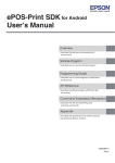
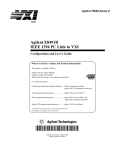
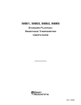
This document describes a software and hardware solution concerning the STM32x
microcontroller and the STPM01 power meter for measuring mains power consumption and
also provides hardware and firmware guidelines to interface the STPM01 with the STM32x
microcontroller. Figure 1 shows the block diagram of the solution. The system described in
this document is the first “brick” to build a complex system for distributed load management.
Figure 1.
Block diagram
AM00076v1
November 2008
Rev 1
1/14
www.st.com
Contents
AN2799
Contents
1
File organization . . . . . . . . . . . . . . . . . . . . . . . . . . . . . . . . . . . . . . . . . . . . 3
2
Hardware . . . . . . . . . . . . . . . . . . . . . . . . . . . . . . . . . . . . . . . . . . . . . . . . . . 3
2.1
STM32F103xx microcontroller . . . . . . . . . . . . . . . . . . . . . . . . . . . . . . . . . . 4
2.1.1
2.2
STPM01 . . . . . . . . . . . . . . . . . . . . . . . . . . . . . . . . . . . . . . . . . . . . . . . . . . 5
Hardware description . . . . . . . . . . . . . . . . . . . . . . . . . . . . . . . . . . . . . . . . . 5
3
Functional description . . . . . . . . . . . . . . . . . . . . . . . . . . . . . . . . . . . . . . . 7
4
Firmware description . . . . . . . . . . . . . . . . . . . . . . . . . . . . . . . . . . . . . . . . 7
4.1
4.2
Power meter object description . . . . . . . . . . . . . . . . . . . . . . . . . . . . . . . . . 7
4.1.1
Attributes . . . . . . . . . . . . . . . . . . . . . . . . . . . . . . . . . . . . . . . . . . . . . . . . . 9
4.1.2
Methods . . . . . . . . . . . . . . . . . . . . . . . . . . . . . . . . . . . . . . . . . . . . . . . . . . 9
4.1.3
Construction . . . . . . . . . . . . . . . . . . . . . . . . . . . . . . . . . . . . . . . . . . . . . . 10
4.1.4
Deletion . . . . . . . . . . . . . . . . . . . . . . . . . . . . . . . . . . . . . . . . . . . . . . . . . 11
Hardware abstraction layer . . . . . . . . . . . . . . . . . . . . . . . . . . . . . . . . . . . . 11
4.2.1
4.3
HAL functions . . . . . . . . . . . . . . . . . . . . . . . . . . . . . . . . . . . . . . . . . . . . 11
Application interface . . . . . . . . . . . . . . . . . . . . . . . . . . . . . . . . . . . . . . . . . 11
4.3.1
Application interface functions . . . . . . . . . . . . . . . . . . . . . . . . . . . . . . . . 12
5
Conclusion . . . . . . . . . . . . . . . . . . . . . . . . . . . . . . . . . . . . . . . . . . . . . . . . 12
6
Revision history . . . . . . . . . . . . . . . . . . . . . . . . . . . . . . . . . . . . . . . . . . . 13
2/14
AN2799
1
File organization
File organization
The following table presents the firmware modules.
Table 1.
Firmware modules
File
Description
PowerMeterHal.h
Definitions of power meter hardware abstraction layer types and function
PowerMeterHalTypes.h prototypes.
PowerMeterObj.h
PowerMeterTypes.h
PowerMeterHal.c
PowerMeterObj.c
Meterlayer.h
Meter.c
MeterHal.c
ExampleApp.c
2
Definitions of power meter abstract objects and types.
Power meter hardware abstraction layer and abstract object
implementation
Definitions of application interface types and function prototypes
Application interface and hardware abstraction layer implementation
Library usage example
Hardware
The solution is based on the STM32F103xx in the LQFP64 package with 128 kB of Flash
and 20 kB of SRAM for demonstration purposes, but it can be easily ported on the smaller
STM32F101xx microcontroller family based on the same ARM Cortex™-M3 CPU as well.
The device used to measure the phase AC current is the STPM01 with a current
transformer.
3/14
Hardware
2.1
AN2799
STM32F103xx microcontroller
The following list is a brief description of the features of the STM32F103xx microcontroller.
Please refer to the STM32F103xx datasheet for a more detailed description of the device.
●
●
●
●
●
●
●
Core: ARM 32-bit Cortex™-M3 CPU
–
72 MHz, 90 DMIPS with 1.25 DMIPS/MHz
–
Single-cycle multiplication and hardware division
Memory
–
32-to-128 Kbytes of Flash memory
–
6-to-20 Kbytes of SRAM
Clock, reset and supply management
–
2.0 to 3.6 V application supply and I/Os
–
POR, PDR, and programmable voltage detector (PVD)
–
4-to-16 MHz quartz oscillator
–
Internal 8 MHz factory-trimmed RC
–
Internal 40 kHz RC
–
PLL for CPU clock
–
32 kHz oscillator for RTC with calibration
Low power
–
Sleep, stop and standby modes
–
VBAT supply for RTC and backup registers
2 x 12-bit, 1 µs A/D converters (16-channel)
–
Conversion range: 0 to 3.6 V
–
Dual-sample and hold capability
–
Temperature sensor
DMA
–
7-channel DMA controller
–
Peripherals supported: timers, ADC, SPIs, I2Cs and USARTs
Debug mode
–
●
–
●
●
26/36/51/80 I/Os, all mappable on 16 external interrupt vectors, all 5 V-tolerant
except for analog inputs
Up to 7 timers
–
Up to three 16-bit timers, each with up to 4 IC/OC/PWM or pulse counter
–
16-bit, 6-channel advanced control timer: up to 6 channels for PWM output dead
time generation and emergency stop
–
2 watchdog timers (independent and window)
–
SysTick timer: a 24-bit down counter
Up to 9 communication interfaces
–
4/14
Serial wire debug (SWD) & JTAG interfaces
Up to 80 fast I/O ports
Up to 2 I2C interfaces (SMBus/PMBus)
AN2799
Hardware
●
2.1.1
–
Up to 3 USARTs (ISO 7816 interface, LIN, IrDA capability, modem control)
–
Up to 2 SPIs (18 Mbit/s)
–
CAN interface (2.0B Active)
–
USB 2.0 full speed interface
Packages are ECOPACK® (RoHS compliant)
STPM01
The STPM01 is a programmable single-phase energy metering IC which is designed for
effective measurement of active, reactive and apparent energy in a power line system using
a Rogowski coil, a current transformer and shunt sensors. The solution presented in this
document is based on a current transformer sensor. The following list is a brief description of
the main features of the STPM01. For more details, please refer to the device datasheet.
2.2
●
Active, reactive, apparent energies and RMS values
●
Ripple-free active energy pulsed output
●
Live and neutral monitoring for tamper detection
●
Easy and fast digital calibration in only one point over the whole current range
●
OTP for calibration and configuration
●
Integrated linear VREGS for digital and analog supply
●
Selectable RC or crystal oscillator
●
Supports 50-60 Hz - IEC62052-11, IEC62053-2X specification
●
Less than 0.1% error
●
Precision voltage reference: 1.23 V and 30 ppm/°C max
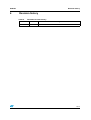
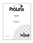
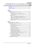
Hardware description
The hardware used in managing the STPM01 by the STM32x microcontroller is described in
this section. Figure 2 shows a reference schematic to interface the STM32x microcontroller
with the STPM01. The STPM01 bidirectional data line is connected to the SPI-MISO of the
STM32. This is because the speeds for the data read and data write operations of the
STPM01 SPI interface are much too different: 32 MHz for the read operation and 100 kHz
for the write operation. In fact during the write operation, the serial communication is
emulated by software to have very slow communication on the STPM01 data line and during
the read operation, the STM32 SPI peripheral is used to reach the maximum speed
possible. Since the maximum speed of the STM32 SPI is 18 MHz, it doesn't matter which
SPI peripheral is used to have the maximum read bit rate. In this application the SPI2 is
used. The STPM01 clock is provided by the PA8 pin configured as the MCO alternate
function. The AC current is provided to the STPM01 by a current transformer connected to
the current channel 1. For more details about analog parts related to the STPM01, please
refer to the STPM01 datasheet.
Note:
The solution has been validated using the “SmartPlug” board. For further details please
refer to the “SmartPlug hardware user manual” .
5/14
T1
C4
100nF
10
mains
2
1
W3 W2
N
Mor2
N
L
6.8
R68
D6
1N4148
C5
0nF
100n
6.8
R15
ansf ormer
Currentt Tran
C3
1nF
1n
L
N_LINE
L_LINE
R16 1k
R14 1k
261K
R19
10nF
C9
C6
100nF
10
VDD
DD_33
261K
R20
C7
100nF
10
C8
0nf
100n
261K
R21
2M
R17
20
1
ZCR0 2
4
5
6
8
7
9
10
STPM01
led
MON
MOP
Vddd
Vss
Vcc
Vdda
Votp
Ilp1
Iln1
U4
Sda
Scl
Scs
Sy n
CLKou
out
CLKin
Vin
Vip
Iln2
Ilp2
19
18
3
15
17
16
14
13
12
11
MCO
R22 150K
15
0R
R66
R18
47
475
2,21K
C11
0nF
10n
R23
2.4k
R11
D3
2.4k
R13
D5
SY N0
VDD
DD_IO#99
VDD
DD_33
2.4k
R12
D4
VDD
DD_33
1
2
1
2
1
2
VOTP
1
2
D2
R10
2.4k
C60
20p
20
C58
10pF
Y2
8MHz
R108
1M
SPI0_MISO
SO
SCS0
SCLK
768 Khz
32.76
Y1
C54
00n
100
C56
100n
C61
20p
SW11
Rst
RESE
SET#
C59
10pF
OSC-32-OUT
OS
OSC-32-IN
OS
C55
100n
C63
10n
R109
10K
VCC
CC_3V3
C62
100n
SY N0
JT-TMS
JT-TCK
JT-TDI
C57
100n
R11
110
100K
MCO
13
12
60
7
5
6
54
14
15
16
17
20
21
22
23
41
42
43
44
45
46
49
50
GND
VDD_IO#99
VCC
CC_3V3
V3
GND
ND_LINE
VDD33_LINE
NRST
NR
ST
STM32F103RBT6
VDD
DDA
VSSA
VS
BOOT0
BOO
PB
PB0/ADC-IN8/TIM3-CH3
PB1/ADC-IN9/TIM3-CH4
PB
PB2/BOO
BOOT1
PB3/JTDO
PB4/JTRST
PB
PB5/I2C1-SMBA1
PB
PB6/I2C1-SCL/TIM4-CH1
PB
PB7/I2C1-SDA/TIM4-CH2
PB8/TIM4-CH3
PB
PB9/TIM4-CH4
PB
PB10/I2C2-SCL/USART3-TX
PB11/I2C2-SDA/USART3-RX
PB
PB1
B12/SPI2-NSS
SS/I
/I2C2-SMBA
BA1/USART3-CK/TIM1-BK
BKIN
PB13/SP
PB
SPI2-SCK/USART3-CTS/TIM1-CH1N
1N
PB14
14/SPI2-MISO/USART3-RTS/TIM1-CH
CH2N
PB15
15/SP
SPI2-MOSI/TIM1-CH3N
PD0/OSC-IN
PD1/OSC-OUT
PD2/TIM3-ETR
26
27
28
55
56
57
58
59
61
62
29
30
33
34
35
36
8
9
10
11
24
25
37
38
39
40
51
52
53
2
3
4
JTA
TAG PRO
ROG/DEB
EBUG
G CONNE
NECTOR
JT-TMS
JT-TCK
JT-TDI
JT-TDO
JT-TRS
RESET#
PA
PA0-WKUP/USA
SART2-CTS/ADC
DC_IN0/TIM2-CH
CH1-ETR
PC0/ADC
DC-IN10
PA1/USA
PA
SART2-RTS/ADC
DC-IN1/TIM2-CH
CH2
PC1/ADC
DC-IN11
PA2/USA
PA
SART2-TX/ADC-IN2/TIM2-CH3
PC2/ADC
DC-IN12
PA3/USA
PA
SART2-RX/ADC-IN3/TIM2-CH4
PC3/ADC
DC-IN13
PA4/SPI1-NSS
PA
SS/USART2-CK/ADC
DC-IN4
PC4/ADC
DC-IN14
PA5/SPI1-SCK/ADC-IN5
PA
PC5/ADC
DC-IN15
PA6/SPI1-MISO
PA
SO/ADC
DC-IN6/TIM3-CH
CH1
PC6
PA7/SPI1-MOSI/
PA
I/ADC
DC-IN7/TIM3-CH
CH2
PC7
PA8/USA
PA
SART1-CK/TIM1-CH
CH1/MCO
PC8
PA9/USA
PA
SART1-TX/TIM1-CH2
PC9
PA10/USART1-RX/TIM1-CH
PA
CH3
PC10
PA11/USART1-CTS/CAN-RX/USBDM(2)/TIM1-CH
PA
CH4
PC11
PA12/USART1-RTS/CAN-TX/USBDP(2)/TIM1-ETR
PA
PC12
PA13/JTMS-SWDAT
PA
AT
PC13/ANTI-TAMP
PA14/JTCK-SWCLK
PA
PC14/OSC32-IN
PA15/JTDI
PA
PC15/OSC32-OUT
U12
VCC_3V3
1
VBAT
AT
32
48
64
19
VDD
DD1
VDD
DD2
VDD
DD3
VDD
DD4
6/14
VSS1
VS
VSS2
VS
VS
VSS3
VSS4
VS
ZCR
CR0
SCS0
S0
SCLK
SPI0_MISO
SP
JT-TDO
JT-TRS
OS
OSC-32-IN
OSC-32-OUT
OS
JTAG-TMS
JTAG-CK
JTAG-DI
JTAG-DO
JTAG-RS
JTAG-RST
Figure 2.
31
47
63
18
VCC_3V3
Hardware
AN2799
Schematic diagram
AM00077v1
AN2799
3
Functional description
Functional description
The STPM01 host interface is a single bidirectional data line SPI with a 32 MHz maximum
read speed and 100 kHz maximum write speed. Due to these requirements the STM32
microcontroller is used in the following way:
4
●
In the reading phase, the MISO and SCLK pins are configured in alternate functions
and used by the SPI2 peripheral. The maximum reading speed is 18 MHz by an APB
speed equal to 36 MHz, configuring the SPI baud rate with APB/2.
●
In the writing phase the MISO and SCLK pins are configured as GPIOs and the SPI
operation is emulated by firmware controlling the speed operations to not exceed the
100 kHz writing speed limit. The MCO pin is configured to provide the HSE clock.
Firmware description
The firmware for the management of the STPM01 energy meter has been developed using
an object oriented programming (OOP) approach even if standard ANSI C programming
language has been used.
4.1
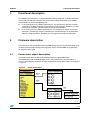
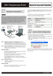
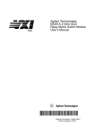
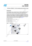
Power meter object description
The power meter object is defined and implemented in the PowerMeterObj.c,
PowerMeterObj.h and PowerMeterTypes.h files. The power meter is represented by a
structure containing the properties and the method of the Power Meter Object as illustrated
in Figure 3.
Figure 3.
Power meter object
AM00078v1
7/14
Firmware description
AN2799
POWER_METER_OBJ
#define POWER_METER_OBJ
PM_u32
m_Voltage;
PM_u32
m_Current;
PM_u32
m_Energy ;
PM_RegistersType Registers;
PM_SignalsType
Signals;
PM_ErrStatus
(* Create)(PowerMeterType*);
PM_ErrStatus
(* Destroy)(PowerMeterType*);
PM_ErrStatus
(* Init)(PowerMeterType*);
PM_ErrStatus
(* Reset)(PowerMeterType*);
PM_ErrStatus
(*SetSignals)(PowerMeterType*,PM_SignalsType* pSignals);
PM_SignalsType* (*GetSignals)(PowerMeterType*);
PM_ErrStatus(*SetCfgRegsMode)(PowerMeterType*,PM_CfgRegsModeType CfgRegsMode);
PM_ErrStatus(*WriteConfigBit)(PowerMeterType*, PM_u8 uBitAddress, PM_u8
uBitValue);
PM_ErrStatus(*WriteConfigRegs)(PowerMeterType*,PM_u32 uCFL_Value, PM_u32
uCFH_Value);
PM_ErrStatus
(*ReadRegisters)(PowerMeterType*, PM_u8 RegsToReadNum);
PM_ErrStatus
(*ReadMeasure)
PM_u32
(*GetVoltage)(PowerMeterType*);
PM_u32
(*GetCurrent)(PowerMeterType*);
PM_u32
(*GetEnergy)(PowerMeterType*);
PM_ErrStatus
(*OnSpiRxIrq)(PowerMeterType*);
typedef struct PowerMeter
typedefs */
struct PowerMeter {
POWER_METER_OBJ
};
8/14
(PowerMeterType*, PM_u8 MeasureType);
PowerMeterType;
/* Forward declaration for circular
AN2799
4.1.1
Firmware description
Attributes
The object attributes are described as follows:
●
m_Voltage: “private” variable containing the last read voltage in mV
●
m_Current: “private” variable containing the last read current in mA
●
m_Energy: “private” variable containing the last read energy in mW
●
Registers: “public” structured variables containing the STPM01 registers:
●
–
DAP: type0 active energy
–
DRP: reactive energy
–
DSP: apparent energy
–
DFP: type1 energy
–
DEV: RMS values of measured voltage and current
–
DMV: instantaneous values of measured voltage and current
–
CFL: lower part of the configuration register
–
CFH: higher part of the configuration register
Signals: “public” structured variables containing the signals descriptor used to interface
STM32 with STPM01:
–
PM_SCS: this signal enables the SPI operation when low
–
PM_SYN: When SCS is low, this signal selects the read or write operation. When
both SCS and SYN signals are high, the results of the input or output data are
transferred to the transmission latches.
–
PM_SDA: SPI MISO signal. This signal is used as the STPM01 data signal. The
direction of this signal depends on the SYN signal.
–
PM_SCLK: SPI clock signal
Each signal descriptor contains the STM32 port and pin number. For further details about
SPM01 registers and the microcontroller interface, please refer to the STPM01 datasheet.
4.1.2
Methods
The object methods are implemented by means of pointers to functions which are described
as follows:
●
Create: this function initializes all power meter object elements (properties and
methods).
●
Destroy: not used. Implemented to have a general object implementation.
●
Init: this function initializes the power meter object properties and the power meter
signals putting them in the idle state.
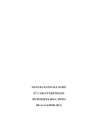
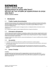
●
Reset: this function executes the reset sequence to perform the “remote reset”
operation of the STPM01 (Figure 4).
●
SetSignals: this function initializes the “signals” attribute of the power meter object and
configures the GPIOs related to the signals.
●
GetSignals: this function retrieves the “signals” attribute of the power meter object.
●
SetCfgRegMode: this function sets the STPM01 configuration register as shadow
latches or OTP. In current AN firmware the STPM01 is configured to use the shadow
latches for the configuration for testing reasons.
9/14
Firmware description
●
AN2799
WriteConfigBit: this function writes a configuration bit of the STPM01 configuration
register formatting an 8-bit command word as the following:
1 bit data
6 bits configuration bits
1 bit don’t care
The configuration word is sent to the STPM01 by the SPI interface.
●
WriteConfigRegs: this function writes the entire CFL and CFH configuration registers of
the STPM01.
●
ReadRegisters: this function reads the registers from the STPM01 and assigns the
read values to the power meter object registers attribute. The number of read registers
depends on the RegToReadNum passed parameter.
●
ReadMeasure: this function reads the RMS voltage and current registers from the
STPM01, calculates the real RMS values by multiplying the values of each register by
the calibration factors and assigns these values to the m_Voltage and m_Current
attributes of the power meter object.
●
GetVoltage: this function retrieves the last read voltage value in mV.
●
GetCurrent: this function retrieves the last read current value in mA.
●
GetEnergy: this function retrieves the last read energy value in mW.
●
OnSpiRxIrq: SPI interrupt event. Not used in this implementation. The SPI interrupt is
managed externally by the power meter object implementation.
Figure 4.
Reset sequence
AM00079v1
4.1.3
Construction
The power meter object is constructed by the NewPowerMeterObj function implemented
externally by the object itself. This function allocates the memory for the object, assigns the
create method and calls it to assign the rest of the object properties.
10/14
AN2799
4.1.4
Firmware description
Deletion
The power meter object is deleted by the DeletePowerMeterObj function implemented
externally by the object itself. This function first calls the deletion method to free dynamically
allocated variables during object creation (in this case does nothing) then frees the allocated
memory for the power meter object.
4.2
Hardware abstraction layer
The HAL is implemented using the following files:
●
PowerMeterHal.c
●
PowerMeterHal.h
●
PowerMeterHalTypes.h
This module is useful to abstract the power meter object implementation from the STM32
standard library.
4.2.1
HAL functions
The hardware abstraction layer functions are described as follows:
4.3
●
PM_ConfigSignal: this function configures a pin according to the passed signal
descriptor and configuration type.
●
PM_ReceiveRegOnSpi: this function receives the STPM01 internal register from the
SPI interface.
●
PM_OnSpiRxIrq: This function implements the interrupt service routine of the SPI
interface. It is called when the FIFO of the SPI peripherals contains 1 byte or more and
assigns the received value to a shared register variable.
●
SendClkToGetData: this function is used to provide the SPI clock to the STPM01 to
receive data.
●
ConfigPin: pin configuration function.
Application interface
The application interface is implemented using the following files:
●
Meter.c
●
MeterHal.c
●
MeterLayer.h
This layer is useful to abstract the application from the specific board used. In fact, the
functions implemented in the described modules allow the hardware configuration of the
specific board used. The firmware described in this document has been validated using the
“SmartPlug” board that includes two STPM01 meters enumerated as
PM_METER_TYPE_CONSUMPTION and PM_METER_TYPE_DISPERSION.
11/14
Conclusion
4.3.1
AN2799
Application interface functions
The application interface functions are described as follows:
●
PM_HwMetersCommonInit: this function configures the SPI peripheral (including the
interrupt controller), the STM32 MCO pin to provide the clock to both STPM01 and a
GPIO as input, useful to select two different operational modes:
–
Normal Mode: typical operational mode.
–
Calibration Mode: used to calibrate the STPM01 devices by an external tool. In
this mode the STM32 provides only the clock to the STPM01 devices.
These configurations are common to both STPM01 devices.
●
M_HwMeterSignalsInit: this function initializes the signals specific for an STPM01. In
detail, the STM32 GPIO is used as the SCS for the specific device. The specific
STPM01 device is selected by an enumerator as already stated.
●
ActivateMeter: this function includes all the operations to be done using the power
meter object for the STPM01 initialization.
All the initialization operations have been included in a single initialization procedure: Init,
establishing a power meter object and the STPM01 device identifier as parameters.
5
Conclusion
Summarizing, this document explains how to interface the STPM01 energy meter device to
the STM32x microcontroller including an easy-to-use firmware library. The firmware library
also includes the file ExampleApp.c which shows how to use the library itself. The user
application has to perform the standard STM32 configuration and simply call the
NewPowerObj for each STPM01 device to allocate the object, call the Init to perform the
power meters related initializations and configurations, call the ReadMeasure method to get
the data from STPM01 device and call GetVoltage and/or GetCurrent to get the last
measurement data.
12/14
AN2799
6
Revision history
Revision history
Table 2.
Document revision history
Date
Revision
27-Nov-2008
1
Changes
Initial release
13/14
AN2799
Please Read Carefully:
Information in this document is provided solely in connection with ST products. STMicroelectronics NV and its subsidiaries (“ST”) reserve the
right to make changes, corrections, modifications or improvements, to this document, and the products and services described herein at any
time, without notice.
All ST products are sold pursuant to ST’s terms and conditions of sale.
Purchasers are solely responsible for the choice, selection and use of the ST products and services described herein, and ST assumes no
liability whatsoever relating to the choice, selection or use of the ST products and services described herein.
No license, express or implied, by estoppel or otherwise, to any intellectual property rights is granted under this document. If any part of this
document refers to any third party products or services it shall not be deemed a license grant by ST for the use of such third party products
or services, or any intellectual property contained therein or considered as a warranty covering the use in any manner whatsoever of such
third party products or services or any intellectual property contained therein.
UNLESS OTHERWISE SET FORTH IN ST’S TERMS AND CONDITIONS OF SALE ST DISCLAIMS ANY EXPRESS OR IMPLIED
WARRANTY WITH RESPECT TO THE USE AND/OR SALE OF ST PRODUCTS INCLUDING WITHOUT LIMITATION IMPLIED
WARRANTIES OF MERCHANTABILITY, FITNESS FOR A PARTICULAR PURPOSE (AND THEIR EQUIVALENTS UNDER THE LAWS
OF ANY JURISDICTION), OR INFRINGEMENT OF ANY PATENT, COPYRIGHT OR OTHER INTELLECTUAL PROPERTY RIGHT.
UNLESS EXPRESSLY APPROVED IN WRITING BY AN AUTHORIZED ST REPRESENTATIVE, ST PRODUCTS ARE NOT
RECOMMENDED, AUTHORIZED OR WARRANTED FOR USE IN MILITARY, AIR CRAFT, SPACE, LIFE SAVING, OR LIFE SUSTAINING
APPLICATIONS, NOR IN PRODUCTS OR SYSTEMS WHERE FAILURE OR MALFUNCTION MAY RESULT IN PERSONAL INJURY,
DEATH, OR SEVERE PROPERTY OR ENVIRONMENTAL DAMAGE. ST PRODUCTS WHICH ARE NOT SPECIFIED AS "AUTOMOTIVE
GRADE" MAY ONLY BE USED IN AUTOMOTIVE APPLICATIONS AT USER’S OWN RISK.
Resale of ST products with provisions different from the statements and/or technical features set forth in this document shall immediately void
any warranty granted by ST for the ST product or service described herein and shall not create or extend in any manner whatsoever, any
liability of ST.
ST and the ST logo are trademarks or registered trademarks of ST in various countries.
Information in this document supersedes and replaces all information previously supplied.
The ST logo is a registered trademark of STMicroelectronics. All other names are the property of their respective owners.
© 2008 STMicroelectronics - All rights reserved
STMicroelectronics group of companies
Australia - Belgium - Brazil - Canada - China - Czech Republic - Finland - France - Germany - Hong Kong - India - Israel - Italy - Japan Malaysia - Malta - Morocco - Singapore - Spain - Sweden - Switzerland - United Kingdom - United States of America
www.st.com
14/14