1
60074100
1 0-90
DH
FttfiorLn"
Owner's Manual
DP AIRGOMETER'"
0€
l.D. No.: o 29419
14-38008
TOOLS REQUIRED:
Adjustable Wrench
This product is covered under one or more of the followinglJ. S. and
9/1 6" WfenCh
foreign Patents us 4'880'225' us 306'330(D)' cAN R- '---
MADE IN U.S.A.
phiilips screwdriver
-
Hammer
Pliers
PLEASE RETAIN THIS MANUAL
IMPORTANT
THIS PRODUCT IS DESIGNED FOR ADULT USE. DO NOT ALLOW CHILDREN TO PLAY ON OR AROUND THIS
PRODUCT.
BEFORE STARTING
IMPORTANT
ANY EXERCISE PROGRAM. IT IS RECOMMENDED THAT YOU CONSULT
YOUR
PHYSICIAN.
IMPORTANT .- REPLACEMENT PARTS
Thank you for purchasing our product. Although we go
tc, great effort to ensure the quality of our products, occasionally errors or omissions occur. Should you find
that a part of this product is either missing or defective,
please contact us for a replacement at the following
address or telephone nu mber.
You MUST have the Serial Number of this fitness
equipment ready for the Customer Service Representative in all communications.
In the United States, call 1-800-633-5730, or write to:
Diversif ied Products Corporation
P.O. Box 100
Opelika, AL 36803
Attn: Customer Service
lf you live in the United Kingdom, Western Europe, or
the Middle East, contact:
Diversified Products Limited
Garngoch lndustrial Estate
Phoenix Way
Gorseinon. Swansea
United Kingdom
Attn.: Customer Service - Parts
Tel.: (0792)893854
Tefex: 48687 DIVPRO
O 1990 Diversified Products Corooration
"gIE
d!=
- --:-?h-u9P
IMPORTANT.- SAFETY
TO AVOID ACCIDENT OR INJURY READ AND FOLLOW THESE SIMPLE SAFETY RULES.
1.
2.
Do not allow children to play on or around the DP
AIR GOMETERTM when it is in use.
Regularly check
to see that all nuls, bolts, and
screws are securely tightened.
3.
Keep hands and feet away from linkage
mechanism.
4. Always check to see that seat is securely fastened
before using the DP AIR GOMETERTM.
5.
6.
7.
L
Do not ride standing up.
Do not ride while wearing loose robes, gowns,
loose pants, long skirts, or jewelry such as necklaces, chains, rings, etc..
Always wear rubber soled shoes such as tennis
shoes when using your DP AIR GOMETERTM.
Do not position your DP AIR GOM ETERTM on loose
rugs or uneven surfaces.
9.
Do not place head, hands, or legs between handle-
bars.
10.
The DPAIR GOMETERTM should notbeusedwhen
alone.
Why EXERCISE
is. simple - to.live a,longer, happier.and healthier life. lt is known that a planned., regr+{jAgq?S
programcantmprovephysicalandmentalhealth.T6oofteh'ourlifestylelimitsouriimeoropportunitytoexercise. IheDPAIH
Why exercise.? The answer
GO"Vgfe n.M piovides aconvenient and simple method to embark on a program ol self improvement.
Cycling and Rowing are recognized as two of the best forms of exercise. With the DP AIR GOMETERTM the benefit of these exeicisei can now bdper,formeE within the safety and comfort of your own home and at your convenience.
The Dp AIR GOMETERTM provides the user with the latest, most accurate electronic means.of measuring the.quantity ol energiicaioiies) ;xpended durihg exercise. tnis information is blectronically calculated and displayed for each individual based on
his or her age, sex, and pulse rate.
With the MONTTOR you can pre-set (1) the time you wish to exercise (2) the distance "traveled" (3) the pace (cadence) at which
you wish to work and (4) the amount of calories you wish to burn.
Included in this booklet is a program designed to put you on the road to improved physical condition. Good exercise habits will
help you feel better, look better and enjoy life more fully.
Training Tips
Consult Your physician before starting this or any other physicaltraining program.
Start your exercise program now! Don't procrastinate.
3. Each training session should consist of :
a. Five tolen minutes of stretching and warm up and a minute or two of relaxed riding at a slow pace.
b. A target pulse rate exercise.
c. A coo-l dciwn period of lrom one to to two minutes of slow relaxed riding and some gentle stretching.
4. For best results, include a good approved diet and start it simultaneously with your exercise program.
5. proper attire includes cotton shorts and T-shirt for warm weather or a polyester, acrylic, or cotton warm-up suit for cooler
weather.
6. Do not attempt to progress too rapidly. Gradually increase the intensity of your workouts.
7. Breathe deeply while exercising. Don't hesitate to breathe through.your mouth.i{ you need more oxygen. Use the "Talk Test"'
lf you cannoi iarry on a conveisation while training, you are working too hard!
8. Rest is essential. No exercise program can improve your f itness il you do not get adequate rest.
9. Schedule your exercise. Beginners - Excercise ev.gry other day-for at least a month. Intermediates Exercise at least five
by one day of
followed
consecutively
you
days
three
exercise
ldeally,
shouid
generatty
six.
n"ot
more
than
OiVJi-*e'e6 Oul
redt, then two days of exercise followed by a day of rest.
1 0 . There is no "best time" to train. The important thing is to train when your energy is hrgh. Some individuals f eel better training
Orrring inJeirti morning hours and others in thdevening. Throufh experim-e.ntation you,must find your own ideal time.
Howe-ver, you dhould avoid training within two hours alter eating or one hour prior to a meal.
1.
2.
Pre-exercise Stretch i ng
A thorough warm up of the large muscles used in your training program will help avoid pulls,, st;qi5s _1n! gl.|qp.tj-T!^.-!oll.oy]19
stretcheiwillhelpprepareyorltoenjoyyourexercisesession.Holdeachstretchforacount0f
l5andrelax. Inenrepeateacn
severaltimes.
Begin by bending at the hips and place your hands on your knees. Lower your head toward the f loor until you feel the stretch in
the-back of your thighs and press back on your knees with steady preasure,
you
Using a wall or other large object to steady you, grasp one foot and gently pull it as close to your buttocks and as high as
can. Repeat with the other foot.
Turn towards the wall and place both hands on it and support yourself with one Ieg while the cther is placed behind you.with.the
tensote flat on the tfoor. ben! inelorwirO teg and lean towaicis thrS wall keeping the rear leg straiglt so that the calf and achilles
60; t;e atretched. nepeatioi the other tEg. Some benelit lor the upper'Oody can also be derlved f rom this stretch.
Next, Sit on the lloor and draw your legs up toward your groin, the soles of your f eet together and holding your back straight,
lean forward over your feet.
Warm up (Minimum of 5 minutes total)
ponion of the handlebars to
Stand direcily in front of the Dp AIR GOMETERTM, with your feet set apart.slighlly to allow the tower
noderate
fodh
a
at
back
and
handles
nxrve
the
alternately
and
handlegrips
move treety.'Grasp the
.pace'
AiVourleriarm eitenOs,-iuiniorirnips and headio the right. Reverse this motion as the right arm is extending.
your
ADVANTAGE: This rotation provides stretch and f lex o{ the lower back, upper shoulders and neck while slowly increasing
pulse rate and blood circulation.
Stand behind the DP AIR GOMETERTM with the balls of yourfeet on the floor tube, lean over the seat and grasp the handlegrips.
Alternately move the handles back and forth at a moderate pace. Turn the upper body and head to the right as you extend your
left arm. Reverse this motion as the right arm extends.
ADVANTAGE: Provides stretch and f lex of the upper back and sides while slowly increasing the pulse rate and blood circulation.
Sitting on the DP AIR GOMETERTM, place your hands on the handlegrips (or rest them on your thighs). Place the balls of your
feet on the pedals and slowly begin pedaling.
ADVANTAGE: Provides flex to hip, knee, and ankle joints while slowly increasing the pulse rate and blood circulation.
The Exercise Program*
CONSULT YOUR PHYSICIAN BEFORE PARTICIATING IN THIS OR ANY OTHER
PHYSICAL TRA]NING PROGRAM
lqchpels_o4.is different in age, weight, and overallfitness; each must tailor their program to their own needs. The DP AIR
GOMETERTM with its electronic MONITOR will simplify attainment of your goal.
In any program of exercise, maximum physical benefit will be realized only when exertion occurs. However;the old adage "No
p_a!n, 1qgqi1" is NOT true in terms of simple cardiovascular training. Your pulse rate is a good indicator of exertion. The DP AIR
GOM ETERTM allows you to continuously monitor your pulse rate and thus t'ailor your trainihg program to suit your level of f itness.
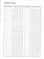
To begin, f irst determine at what level of fitness you are. We strongly urge that you involve your physician in this basic decision.
Then find your age group in the age column of the training chart (below) and lead acrossthe chart to the right to find the appropriate pulse rate range for you. Use these numbers to set the pulse targets on your MONITOR.
As you-beg_in to use
e your DP AIR GOMETERTM, work at the lower end of your target pulse range. As you progress
that you
vou will need to ride faster in order to stay
stav in the pulse
oulse range
ranoe you
vou have chosen. This is your
voirr body's
I
way of tel
your fitness.is increasing. As this occurs, you may begin to work in the higher end of your pulse range. lf you started in the "Low
Fitness." training program, you may increase your pulse rate a little eaclrweek after the first month-until-you are working in the
desired'target pulse rate range for your age bracket.
Wh3t! gvgr ygq[ P.eJcgiyedJ@es_q level, unless you are already cycling more than 5 miles daily, plan to start your program slowly. Ride the DP AIR GOMETERTM at a low speed and thus a lbw level of resistance and trainioi only a shorf peribd every other
day for the f irst two weeks. Every week add a few minutes per session until you are exercising for at least tr,ienty minutbs at a
time. As your f itness improves, you may wish to exercise five or six days a week.
Since the MONITOR will calculate the number of calories u'sed, you may decide to work using calories rather than relying on
time.
EACH TRAINING SESSION SHOULD CONSIST OF:
1. FROM FIVE TO TEN MINUTES OF STRETCHING AND WARM UP AND A MINUTE OR TWO OF RELAXED RIDING AT
A SLOW PACE.
2. TARGET PULSE RATE EXERCISE.
3. A COOL DOWN PERIOD OF FROM ONE TO TWO MINUTES OF SLOW. RELAXED RIDING AND SOME GENTLE
STRETCHING.
Training Ghart*
AGE
16 - 20
21 -25
26-30
31 -35
36-40
41-45
46-50
51 -55
56-60
61 -65
Over 65
LOW FITNESS
TRAINING
HIGH FITNESS
TRAINING
120 - 130
115- 125
115- 120
- 150
- 145
- 145
- 135
115- 135
115- 130
110-125
105 - 125
105 - 120
100 - 115
100-110
130
125
120
120
110-120
110-115
105 - 115
100-110
95 - 105
90 - 105
85 - 100
85 - 100
CARDIOVASCULAR
TRAINING
150 145 145 135 135 130 125 125 120 -
170
165
160
155
155
150
145
140
135
115- 130
110 - 125
WAHNING: Persons Over 50 Years Of Age Must Not Exceed The Pulse Rate Schedule For Their Age Group.
*Exercise program and training
chart based on Sharkey, Brian J., 1984, Physiology of Fitness, 2nd ed., Human Kinetics Publishers, Inc., Champaign, ll.
3
Using the DP AIR GOMETERTM
The secret to aerobic training is achieving a selected heart rate and maintaining it. The DP AIR GoMETERTM, with its air
resistance sytem and integrated electronic MONITOR allows the user to easily attain the desired pulse rate.
Since no two people or life styles are alike, the DP AIR GOMETERTM has been designed to allow the user to isolate portions of the body that may need greater emphasis in training.
These exercises provide cardiovascular conditioning, muscle toning and joint llexing with the ability to exercise both the
upper and lower body simultaneously or independently. Increase the workout intensity by increasing the speed of the leg
and/or arm movements.
1. Position the seat so that you are comfortable and your leg is extended as lar as possible when your heel is on the pedal
and the pedal is in its lowest position.
2. Place the "BALL" of your foot on the pedal for proper pedaling position.
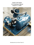
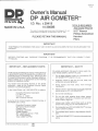
The following photographs illustrate the basic positions for use of your DP AIR GOMETERTM
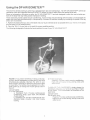
FIGURE 1. FULL BODY WORKOUT: Sitting cornfortably erect, use the handlebars to either push or pull while
simultaneously pedaling. Alternate the effort to your
arms or legs to intensify or reduce the work of the upper
or lower body. The handles may be gripped from underneath (palm up) to change the muscle groups used in
2. For the lower body:
Pedaling: Provides cardiovascular conditioning,
thigh and catf muscle toning, and hip, knee, and
ankle flexion
the arm.
To ISOLATE THE LOWER BODY, simply release the
ADVANTAGES:
1. Forthe upperbody:
as you pedal. This concentrates the exercise on the
Iower body
a. Handlebar Push: Provides cardiovascular
conditioning, tricep, upper back, and shoulder
muscle training.
b. Handlebar pull: Provides cardiovascular conditioning, bicep, shoulder, and chest muscle
training.
handlebars and place your hands on your hips or thighs
.
ADVANTAGES:
For the lower body:
Pedaling : Provides cardiovascular conditioning,
thigh and calJ muscle toning, and hip, knee, and
ankle f lexion.
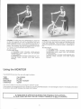
FIGURE 2. To ISOLATE THE UPPER BODY, ptacefeer
on the foot supports and use the handlebars'and your
arms to activate the fan. Try to minimize the amouht of
torso twisling to just that necessary to complete the exercise. The handles may also be gripped from beneath
to change the muscle groups used in the arms.
ADVANTAGES:
For the upper body:
a. Handlebar Push: Provides
cardiovascular
conditioning, tricep, upper back, and shoulder
muscle training.
b. Handlebar pull: Provides cardiovascular conditioning, bicep, shoulder, and chest muscle
training.
FIGURE 3. To EXERCISE THE TORSO, stand with feet
on the foot tube, lean over the seat and aclivate the fan
using the handlebars. This exercise is most effective
when the muscles of the torso are used in a twisting motion.
ADVANTAGES:
Forthe upper body:
a. Handlebar Push: Provides cardiovascular
conditioning, tricep, upper back, and shoulder
muscle training.
b. Handlebar pull: Provides cardiovascular con-
ditioning, bicep, shoulder, and chest muscle
training.
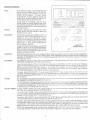
Using the MONITOR
The MONITOR provides the user with eight functions:
TIME
SPEED
DISTANCE
CADENCE
CALORIES
PULSE
PULSE TARGET
SCAN
The unit is turned on and off by pressing the ON/OFF button.
The functions are changel fLom one to another by pressing the MODE button. A smalltriangle is shown in the display arcaabove
the function name which indicates the mode that is active.
A
IS OPERATIVE WHEN THE TRIANGLE IS FLASHING.
AN ONLY BE SET WHEN TRIANGLE IS NOT FLASHTNG.
Setting Functions
TIME:
SPEED:
DISTANCE:
Press ON/OFF button. Unit will indicate 0:00
time and show triangle above time function
name. To time your exercise, press the
START/STOP button. To stop, press
START/STOP. Press it again to resume. To
reset to 0:00, stop the function and press UP
and DOWN buttons at the same time.
To set TIME for countdown, use the UP or
DOWN button to set the desired time. Start
the TIMER by pressing START/STOP button.
An alarm will sound lor 10 seconds when the
time has expired.
SPEED is displayed in miles per hour. Press
MODE button until the triangle is above the
SPEED function name.
DISTANCE is displayed in tenths of a mile. To
record DISTANCE, press MODE button until
triangle is above the DISTANCE function
name. Set the display to read 00.0 by pressing both the UP and DOWN buttons at the
same time. To stop, press START/STOP.
MCDt
T)
t\ T
)tA
-T
-\
\l
t--\
7
Press it again to resume.
To set D|STANCEforcountdown, use UP and
CADENCE:
CALORIES:
DOWN buttons to set the desired distance.
Start countdown by pressing START/STOP.
An alarm will sound lor ten seconds when the
distance has been reached.
CADENCE will allow you to set an audible tempo to pace yourworkout. Set the desired tempo (displayed in
beats per minute) using the UP and DOWN butions. Press starVstop to begin and again to stop. Reset tempo
using ihe UP ancj DOWN buttons. The CADENCE may be set f rom 15 to 120 beats per minute in increments
of 5 beats per minute.
CALORIES are based on AGE, SEX, and PULSE RATE. CALORIE MODE MUST BE USED IN CONJUNCTION WITH PULSE INPUT FROM THE EAR CLIP.
Press the Mode button untilthe smalltriangle is visible above "AGE/SE)0CALORIE" and the_word 'IAQF^qp:
pears on the left side of the display. Use the UP or DOWN buttons to select your correct age. Press the MODE
button to set and a smallfiguie will appear on the left side of the display. Use the UP button lo choose the
f igure descriptive of your sex (male oi iemale). Press MODE once more to set. lf necessary, set the display
to 0.0 by pressing both UP and DOWN buttons at the same time.
To begin, press START/STOP. To stop, press START/STOP. Press it once more to resume.To use the
CALOFIE bountdown feature, use the UP and DOWN buttons to set the number of calories you desire to use
and start by pressing START/STOP. An alarm will sound for 10 seconds when you have used the set number of calories.
PULSE displays your pulse rate in beats per minute. Place the ear clip on your earlobe and plug the cord into
the receptacle provided at the bottom of the monitor.
The PULSE circuit is designed to identify consistent pulse patterns. lf a consistent pattern cannot be detected,
or if it senses that a consiStent pattern has become iiregulbr, the monitor displays the letter "P",.denoting that
it cannot find a reliable pulse. to avoid this, the strain ielief clip on the wire should be fastened to your collar
or another piece of clothing while you exercise.
PULSE TARGET: PULSE TARGET allows you to set a target range for your pulse rate during a wod<out. For further information, refer to the exercise program and training chart.
To set the HIGH TARGET value, be sure that PULSE TARGET mode is otf (smalltriangle not flashing) and
the word "HlGH" appears along the right side of the display. Then use the UP or DOWN buttons to select the
desired UPPER PULSE RATE. Press MODE to set.
To set the LOW TARGET value, press MODE until "LOW" appears along the right side of display and use the
UP and DOWN buttons to select the desired LOWER PULSE RATE.
To begin, press the START/STOP button. To stop, press START/STOP. Press it again to resume. A series
of threi qtiict< Oeeps followed by a pause will be repeate^d !1fo.ut pulse rate exceeds the HIGH TARGET value
you have set. lf ybur pulse rate descends below ine IOW TARGET value that you have set, a series of two
beeps followed by a p'ause will be sounded untilthe pulse rate is again within the desired range.
SCAN:
SCAN will automatically cycle through allthe displays except AGE, SEX, and PULS-E TA.RG.ET, changing
every eight seconds. piesi rulOOe uhtil tne word "SCAN" appears on the right side of the display.
PULSE:
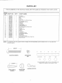
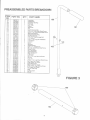
PARTS LIST
ITEM NUMBERS IN THE INSTRUCTIONS ARE THE SAME AS THOSE IN THE PARTS LISTS
ITEM
PART NO.
QTY.
'I
39222800
I
z
3038281 6
39 t 90900
1
39244100
1
NO.
3
39221200
21021200
6
7
25001 500
9
29290600
39242900
I
11
1A
1
2
4
1
4
09088700
15
1
391 89441
,l'7
18
19
39201 100
37024741
3 1 200557
20
31 21 871 0
21
02051 100
29293600
26003200
29058400
391 89300
22'
zo
27
1
28041 300
3820 t 01 6
20013300
12
13
zc
1
2
2
2
39243000
42047600
10
23
24
I
1
2
1
2
2
2
2
4
2
1
37023700
I
50074 1 00
I
PART NAME
Handlebar
Connecting Rod
Seat
Frame
Foot Tube
5116" x 2 1/4" Lonq Machine Screw
5/16" Locknut
Large Shoulder Bushing
Rioht Pedal
Left Pedal
Plastic Spacer
Plastic Expansion Nut
Console Bracket
#10 x 3/4" Long Sheet Metal Screw
Bracket Cover
Console
Trianoular Knob
Monit6r
Pivot Rod
Foot Support
Foot Support Cushion
Small Shoulder Bushino
3/8" Washer
Hairpin Cotter
Seat Adiustment Knob
Ear ClipWith Cable And Strain Reliel Clip
Owner's manual
NOTE: The hardware may vary (type of head or length) f rom that specif ied, but the variation will in no way affect the
products quality.
.Al.-
@v
LENGTH
----,1
1/2
MACHINE SCREW
EXPANSION
NUT
1/2
#10 (3/16")
SHEET METAL
SCREW
SHOULDER
BUSHING
HAIRPIN COTTER
3/8'
5/1 6"
a)
@
@
1/2
{l
{l
PLACE WASHER. END OF BOLT OR SCREW, ON
CIRCLE TO CHECK FOR CORRE CT SIZE.
IMPORTANT
PLEASE READ ALL ASSEMBLY INSTRUCTIONS CAREFULLY BEFORE ASSEMBLY.
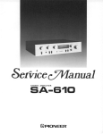
Assembly Instructions
FIGURE
Step
1.
Step
2.
Step
3'
1
Remove the HANDLEBARS (No. 1), CONNECTING RODS (No. 2), SEAT (No. 3), FRAME (No. 4), FOOT TUBE (No.
5), console carton, and the hardware bag from the carton.
NOTE: Be sure that all parts have been removed before discarding carton.
Attach FOOT TUBE (No. 5)to FRAME (No.4)with SCREWS (No. 6) and LOCKNUTS (No. 7).
Push LARGE SHOULDER BUSHINGS (No. 8), with SHOULDER to outside, into CONNECTING RODS (No. 2) as
shown in FIGURE 1 and DETAIL "A".
NOTE: FLAT SIDE of CONNECTING RODS must be to inside as shown in DETAIL "A".
Step 4.
READ ALL OF STEP 4 BEFORE ATTACHING PEDALS
NOTE: The PEDALS are NOTthe same and must be assembled to the proper CRANK. Be sure to match the colored
Iabe|s of CRANKS & PEDALS.
Attach PEDALS (No. 9 HIGHT & 10 LEFT) to corresponding CRANKS (No. 128 RIGHT & 129 LEFT) with CONNECTING RODS (No. 2) and PLASTIC SPACERS (No. 11). PLASTIC SPACERS are positioned between CONNECTING
RODS and CRANKS - see DETAIL "A". Tighten, with 9/16" WRENCH, both PEDALS very tightly by turning toward
REAR of UNIT.
5.
Step 6.
Step
Push PLASTIC EXPANSION NUTS (No. 12) into FRAME CROSSBRACE.
Attach CONSOLE BRACKET (No. 13)to FRAME (No. 4)with SCREWS (No. 14).
NOTE: Use only two SCREWS in the front two holes at this time.
Step
7.
Step
B. Attach BRACKET
Step
9.
Pull gently on the SPEED PICKUP WIRE to remove any slack wire within the FRAME (No. 4).
COVER (No. 15)to CONSOLE BRACKET (No. 13) with remaining two SCREWS (No. 14).
Slide CONSOLE (No. 16) over ends of CONSOLE BRACKET (No. 13), with "DP" towards FRONT, and fasten with
KNOBS (No. 17).
Step'10. Remove MONITOR (No. 18)lrom CONSOLE (No. 16), open BATTERY DOOR, insert BATTERIES (4 "AA"
Alkaline
batteries, NOT INCLUDED), and replace BATTERY DOOR.
Step11. ThreadSPEEDP|CKUPW|REthroughbackof CONSOLE(No.16),plugintobackof MONITOR(No.18),andreplace
MONITOR in CONSOLE.
NOTE: Tuck excess WIRE under MONITOR as it is replaced in CONSOLE.
Step
12.
Step
13. Thread FOOT SUPPORT (No.20)onto PIVOT RODS (No. 19) and tighten with pliers.
14. Moisten with water or liquid soap, and push FOOT SUPPORT CUSHIONS (No. 21) over FOOT SUPPORTS (No. 20).
15. Push SMALL SHOULDER BUSHINGS (No. 22) into holes in front end of CONNECTING RODS (No. 2).
16. Push SMALL SHOULDER BUSHINGS (No. 22), CONNECTING RODS (No. 2), and 3/8" WASHERS (No. 23) onto
Step
Step
Step
Attach HANDLEBARS (No. 1)to FRAME (No.4)with PIVOT RODS (No. 19). Tighten with wrench.
NOTE: When properly mounted, a HANDLEBAR will have its HANDLE pointing away from the AIR GOMETERTM.
PINS at end of HANDLEBARS (No. 1) and fasten with HAIRPIN COTTERS (No. 24).
NOTE: 1.Due to smallvariations in manufacture, HAIRPIN COTTER may not fit into hole in PIN when using two 3/8"
WASHERS. lf this occurs, remove one of the 3/8" WASHERS.
NOTE: 2.HAlRPlN COTTER must be inserted properly - see DETAIL "B'.
Step
Step
17. Remove LOCKNUTS from SEAT (No. 3) and attach SEAT to SEAT POST (No. 106)with LOCKNUTS.
18. Slide SEAT (No. 3)to desired height, align the nearest hole in the SEAT POST (No. 106)with holes in SEAT POST
TUBE, insert, and tighten SEAT ADJUSTMENT KNOB (No. 25).
128 or 129
CRANK
EAR
CLIP
-@
18
CONNECTING
ROD
11
SHOULDER
PLASTIC
SPACER
9
OT
10
''AA'' ALKALINE
PEDAL
DETAIL ''A''
BATTERIES
(not included)
&-tz
\tsrA
\
106
..'-
SPEED
PICKUP
r-r_WIRE
I
1
24
LOCKNUTS
x
LEFT
13
\
--
rRanae
CROSSBRACE
\
23\
\r
24
23
Ara
\[ \r
lrb'2q(l
- FP-\
g'v
mAcef
9
\\r
(ll
\\t
RIGHT
WRONG
//u
DETAIL "B''
\
RrcHT
FIGURE
1
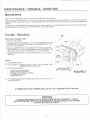
MAINTENANCE / TROUBLE . SHOOTING
Maintenance:
Keep DP AIR GOMETERTM clean by wiping with an absorbent cloth after use.
TwiceeachyearrheSCREWS(No. 109&110)s!qy!g.Pglem.o.vpdtoloosenCHAINGUAFD.qlllo 126&1??angallowthe
reasrArrrGuAnd (r.,ro. r-soj]b oe reriioveo. LuoriciiecHAiN (No. 119) and each end ot the FAN AXLE with machine oiland
semble.
recommended
To store the Dp AIR GOMETERTM simply keep it in a clean dry place. To avoid damage to the electronics it is
that the batteries be removed from the MONITOR (No. 18) before storage'
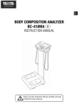
Trouble - Shooting:
Chain makes "popPing" noise.
CHAIN IS TOO LOOSE.
a. To adiust, remove SCREWS (No. 133 & 110), FANGIA|D-(No'-1-36)'
and SCREWS (No. 109 & 130)to loosen CHAINGUARDS (No. 126
and 127) - see FIGURE 4.
b. Loosen LOCKNUTS (No. 115) and tighten NUTS (No. 118) so that
RETAINERS (No. 1 13) are the same-distance lrom FRAME-(No' 1 05)
and all slack is removdd from CHAIN (No. 119) - see FIGURE 2.
c. Replace FANGUARD (No. 136) and SCREWS (No' 133' 110' 109,
and 130).
119
115
113
FAN
AXLE
Monitor
a. TURN MONITOR ON.
b. lF NO DISPLAY: Replace batteries - ONLY "AA" ALKALINE BATTERIES ARE RECOMMENDED
c.
d.
IF NO PULSE SHOWS:
.
.
.
.
'
115
Y
SAME DISTANCE
118
A -.-
BOTH SIDES OF FAN
Are vou in the correct mode?
Check earcliP Pluq insertion.
Massaoe eai tb in-crease circulation.
Trv ear-clip on other ear.
Replace batteries.
FIGURE 2
tF NO SPEED/DISTANCE SHOWS: Check pick up wire connection on
back of MONITOR.
tF PRoBLEM ts NoT GoRRECTED: Call toll free 1-800-633-5730 for service.
NOTICE
rrlsNorNEcEssARYroR-EIU-B