1
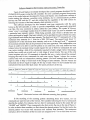
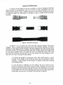
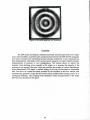
Enhanced controlling of the SLS Process during a build.
Alexandre L. Papadatos, Kenneth Stanley Jr., Said Ahzi and Frank W. Paul
Centerfor Advanced Manufacturing
Department of Mechanical Engineering, Clemson University, Clemson, SC 29634
Abstract
Current commercial Rapid Prototyping(RP) systems like Stereolithography (3D
Systems Corporation) and Selective Laser Sintering (DTM Corporation) use
galvanometers from General Scanning Inc. (GSI) for thepositi()ning of the laser beam.
The GSI scanners are delivered as a ''black box". Operating Consoles which are usually
Personal Computers ·(PC) have ·very few feedback· from the performance of the GSI
scanners. Therefore, the PC spends 900;0 or more of its timewaitingJor the GSI scanners
to be over <with the building of the current layer before sending the information
regarding the next layer. Also, very little process controLcan be performed during the
scanning of a layer using the GSI scanners. This kind of setup prevents any dynamic
controlling of the process·thatcouldprevent building errors like burning, warping etc.
At Clel11Son University, our team hasaevelopedbothhardwareand software
components that allows a dynamic con.trol of the building process. New features like
scanning one vector with laser power as a function of position and/ or time are now
possible. Both hardware and software issues will be presented.
Background
To create objects using the Selective Laser Sintering process, an X Y optical scanner
using CAD solid model data,guides or directs the laser beam to target points requiring
sintering. TheSLS system employs the General Scanning Incorporated (GSI) optical
scanner, the DE series 2000 scanner controller and two G325 DT galvanometers with
mirrors (1,3). The objective of Stanley's work (1) has been to identify the technological
limitations of the GSIoptical scanner, as related to the scanning requirements of SLS,and
present a new optical scanner design based on digital signal (DSP) control theory. One
important accomplishment of the research ..done by Stanley is the use of information
derived ~om the closed loop position control. of the galvanometers to trigger the laser
onloff function. This functionality has been enhanced and .constitutes one of the main
components for the dynamic optical scanning controller.
The GSI system has always been used as a ''black box", and a very small amount of
data is returned to the operating console. We will describe how the build of an object is
managed: the software that supervises the SLS process (the main software) downloads the
informations required to build one single layer into the GSI system. When the
downloading is over, the main software orders the GSI system to go ahead and build (scan)
the layer. The main software then waits for the GSI system to finish. When over, the GSI
system sends an "OK" command back to the main software. Then the main software
becomes aware of the factthafscanning operationsareovefforthatlayer. It then spreads a
new layer of powder and downloads to the GSI •. system the informations required for the
processing of the next layer.
In the GSI system, the laser controlling software that processes the scanning of a
layer cannot be willingly modified. It isa property of General Scanning Inc., and it is
engraved in a memory chip. However, the new controller developed by Stanley (1), uses a
47
Texas Instrument digital signal processor board (4), which is capable of implementing bo~
digital control of the scanning system and supervisory control of the SLS process. A mam
software is still required in order to read the commands for the layers, to perform. e
manao-ement of the controller operation and as a user interface with the system. This IS
mainl~ because the. Texas Instru.ment board cannot access devices such as the hard drive,
the communication ports and the monitor. Therefore, an interface between the board and
these devices is needed, and this is the primary function of the main program in the new
controller system: the dynamic scanning controller. The main difference with the GSI
system is that. the software controlling the laser position, speed and intensity can now be
modified to meet our needs.
tI:
Hardware Designfor the· Dynamic Optical Scanning Controller
The optical scanner developed by Stanley (1) utilizes the actuators •.and sensors of
the GSlscanning systemrbut provides anew controller based on digital signal processing
(DSP).With theDSP based controller, control of the laser tracking is accomplished with
software and control algorithms instead of the hardware controller from the GSI system.
This technique provides thettser with a flexible control environment for laser tracking and
also allows control of laser on/offand laser intensity signals based on the galvanometer's
position. The sensors and actuators have been retained by Stanley in hisDSP based system
because they were the best technology available ·to move the mirrors with the required
performances for rapid prototyping optical scanning.
The controller of theDSP optical scanner uses a C30 digital signal processor system
from Spectrum Signal Processing, Inc. of Westborough, Massachusetts (3). The C30 system
board is designed to coexist in an IBM compatible PC. Data transfer between the DSP and
PC is accomplished through the ISA-ATbus. The C30 system board has 64K of 32 bit RAM
memory that is accessible by both the PC and DSP. These 64K of memory will be split into
two memory banks of 32K each, in order to speed up the process. This feature \lvill be
discussed later in this chapter. More detailed information on the board itself can be found
in (1,3,4).
Since the DPS system uses the same sensors and actuators as theGSI system, an
interface board was required. It has been successfully designed and developed by Stanley
(1). The interface board hooks on the GSI system and allows the control of the SLS process
either with the GSI system or the newer DSP system. All the signal of the DSP / GSI
interface board are designed on one circuit board that is sized appropriately to fit in the
EURO Card Frame of the DE 2000 series controller from General Scanning. A schematic for
the DSP/ GSI interface board and further technical information can be found in Appendix
A of (1).
48
Software Design for the Dynamic Optical Scanning Controller
Terala (2) and Stanley (1) initially developed the control program developed for the
CLEMSON sts project, using the GSI controller. The new controller program incorporates
some of the control software developed by Terala and Stanley. Our contribution consists of
further testing the software, correcting some problems due to communications problem
between the DSP and the PC, and also enhancing the capability of the DSP system by
featuring the variation of the laser intensity while scanning a vector.
The software developed for this research, uses scan commands with the same
format as the GSI controller, in order to prOVide compatibility with previously generated
scan files. One new command is added, called the Laser Setting. The syntax is LSxxxxx
where "xxxxx" is an integer number from 0 to 65535. Each vector can now be scanned with
a particular laser intensity pattern. While being scanned, each vector is divided into ten
zones, each equal in length. One laser intensity can be specified for each of these ten zones.
Eight different levels define the laser intensity. The first level (level "0") represents 2% of the
maximum laser intensity (Le. 1 Watt for a 50W C02 laser). The second level (level "I')
represents 16% of the maximum laser intensity, and so on. At the end, level "7" represents
the maximum intensity that can be provided by the laser apparatus. This configuration was
chosen in order to be able to code the pattern in an octal form. The octal format has been
retained since the decimal format would require the use of three LS commands for each
scan vector, making a total of five commands required to build a single vector. Choosing a
smaller base would not provide such a wide range of power levers. The use of the octal
format requires only two LS commands to describe the way a vector should be scanned,
bringing the total to four commands for each scan vector. Figure 1 shows five vectors,
scanned each with an independent scanning pattern. We have scanned these vectors on
paper in order to keep a visual track of the change in laser intensity. The five vectors are
horizontal and all are equal in length.. On the top of each vector we have added the laser
intensity level for each of the laser zones. The zones are shown at the top.
7
7
7
0
1
2
7
0
7
7
7
7
7
7
7
3
4
5
6
7
7
7
WZ?
6
5
4
3
2
1
0
0
0
2
4
6
7
7
6
4
2
0
7
0
7
0
7
0
7
7
~"'*
7
0
Figure 1. Horizontal vectors with different scanning laser pattern.
In the encoding of the scanning pattern describing these five vectors, two LS
commands are used for each of the vectors. The numbers following the two LS COmmands
describe the pattern. For instance, the two first LS commands found in the script file are
"LS16383" and "LS65535". They correspond to the first vector, the one on the top of Figure 1.
In order to derive these numbers, we first choose the desired pattern. For the first vector the
desired pattern was vector with maximum and uniform laser intensity. The maximum
intensity is level 7; therefore all the ten zones are assigned level 7. In an octal form we have
49
7777777777 describing the desired pattern. Ifwe subdivide this octal number in two integer
numbers, of 16 bit each, we get in binaryform 11111111111111 for the first integer number
(i.e. 16383 in decimal) and 1111111111111111 for the second one (i.e. 65535 in decimal).
Eo.r the second vector, the desiredpattem is 0123456min . octal form or
000001010011100101110111111111.inbinaryfo.rm.We divide this binary number into two
integer 16 bit numbers: 00000101001110 (Le. 334) and 101110111111111 (i.e. 24063). Thus,
the LS commands·for the second vector are "LS334" and 'LS 24063".
Computer Implementation
The control software of the. DSPcontroller has two parts due to the design of the
system (1). The DSP processor requires the support of a hoslcompllter for data storage,
userin.terfaceandcommunication with the SLS machine. Stanley named the program for
thehostPC "PCBUILD.C" and for theDSP system "DSPBUILD.C". ThePCprogramhas
been written using Borland™ C++ v45. When the program<starts, a xnenu is displayed on
the screen. The user can perform from there several actions. In order to start building a
part,the use:. needs to initialize the DSP system by selecting the first option of the menu.
Detailed instructions on how to use the PC program can be fOllnd in (6). The DSP program
has been written inC using a text editor and the special compiler provided by Texas
Instrument. Most of the program is similar·to·the version written by Stanley. However,
some communication problems between the PC and the DSP had risen as the entire system
was used and tested. In order to prevent comrrnmication problems, we have enhanced the
protocol used for the DSP and the PC, by adding stages during the communication, where
the DSP and PC· processors have acknowledge of·each other's status: The DSP waits on the
PC to acknowledge its· status, before .continlling. Then the PC waits its turn on the DSP to
acknowledge its status. Due to <this added checkings,the time for initialization and data
transfer has been slightly increased compared to Stanley's version. However,
communication problems that caused the system to freeze, have virtually disappeared.
Another enhancement over Stanley's version of the DSP program, is the addition of
the laser intensity monitoring. Since theDSP system supervises the scann.irl.g of each vector,
the system is also capable on setting the appropriate laser intensity during the scan of a
vector. The actions corresponding. to theLS commands have been implemented;. The
system monitors the scan of a vector and sets the laser intensity accordingly to the value
specified after the. two· LS commands. In .order for the LS commands to be considered, the
commands "LPO" and "LRO" need to be previously specified. This restriction was chosen to
prevent confusion of the system by opposite commands: LP and·LR commands specify
scanning of vectors with uniform laser intensity, while LS commands specify vectors with
variable laser intensity.
An optimization concerning the time required for data transfer from the PC to the
DSP has been initially designed by Stanley. The 64 kilobytes of memory that the DSP is
equipped in order to stOre data have been divided into two banks of 32 kilobytes each. The
reason that led us to this decision is that the informations for one layer are seldom larger
than 32 kilobytes. This division of the DSP memory allows us to fill one memory bank with
data from one layer, while we process the data of the previous layer stored in the other
memory bank. Therefore, in the ideal context where the time to process a layer is equa.l to
the time to transfer the data into theDSP memory, the data transferring time is reduced by
half. Practically, the laser is always scanning faster the layers than with the GSI system,
since most of the informations for the next layer have already been transferred in the
available memory bank when the laser ends a layer.
Dynamic Controller Results
In order to test the ability of the new controller, we took an existing scan file and
added manually LS commands for each of the vectors. We then ?roceed~d to the build
using the DSP controller. Figure 2 displays the result of the dynarruc scannmg of one lay~r
of a dogbone saIl1ple. We used paper as a Il1ediUIll in order to visually track the dynarruc
scanning.
•
b
<F<
Figure 2. Dynamic scanning
In Figure 2, we can clearly see where the laser intensity changes. The bottom
"dogbone" used a constant laser intensity to proove that dynamic scanning can behave
similarly as when using the GSI controller. The three dogbones have been scanned using
horizontal vectors. The dynamic controller takes each of these vectors and divide them
into ten equal-in-Iength zones. The largest the vector, the largest the zones will be and
th~ worst the resolution will get since we. can only specify one laser setting per zone.
There. are two ways to remedy to this problem.:
1) Increase the number of zones per vector. This would result in a direct
increase of the length of the script file ~ince more LS commands will. be
necessary. A major update of the software is required in this case, including
code programming.
2) Scan the part in a different way. For instance, the use of vertical vectors
instead of horizontal, will result in shorter vectors. Therefore, the zones will
be shorter.and the resolution will also be better. This will lead to an increase
of thelength of the scan and scriptfiles, since more vectors will be generated.
In this latter. case however,noupdate.ofthe software is rEilquired.
51
The Building Script
At Clemson University, a program simulating the SLS process has been developed
and implemented (5,7). Once a simulation has been performed, we are in possession of data
representing the powderbed after the build thatcan be displayed on a computer screen as
a visual representation of the powder bed. These visualrepresentations already provide the
SLS user with important informations on how the build will actually look like. Among
these informations are burning (thermal degradation of the material), bonus z and low
sintering (5). However, without a tool that would modify dynamically the building
parameters, the user can do very little in order to prevent these unwanted phenomena.
The dynamic controller allows supervising the entire SLS process. The dynamic
controller also allows varying the laser intensity settings while scanning a vector. Each
vector can therefore have its. individual laser power setting depending on the geometry.
However, due to the amount of vectors required to build an entire geometry, specifying
manually the laser setting for each vector becomes an impossible task. This difficulty is the
main reason that led us towards the development of a new tool. We will present the
analysis software that uses the results from the simulation software in order to
automaticallyl generate a script file (an improved scan file) which will use the new features
of the dynamic controller.
Automatic Generation of a Scan File
For a machine to perform a task.autornatically, ifis necessary to give the machine
certain guidelines on how to perform in different situations it will encounter. The set of the
guidelines is what we will be calling the "analysis rules" and depending on them, the
machine will perform accordingly in the analysis of the simulation results. The analysis
rule we have adopted as a testbed for our system is based on the maximum temperature
reached in the powder bed. We have been referring to the scan file used by the simulator
and the GSI scanners as the "scan file". We will be referring to the new scan file that is
generated by the analysis software as the "script file", since it also includes informations
regarding the improvement of the build. The scan file and the script file are describing the
same geometry. However, the scan file uses two commands to define a vector, whereas the
script file describes a vector using four commands; the two additional commands describe
the laser power settings for a given vector. The result is that the script file is close to double
the size of the scan file.
For each scan vector describing the geometry, the following procedure is followed:
1) We initialize all the vector zones with the laser setting specified in
the input file. For the sake of simplicity, we have assumed that the laser
setting is higher than needed. Therefore, the laser setting can only be
decreased and the phenomenon of low sintering is not taken into
consideration in the analysis rule presented here.
2) We make sure to identify the vector zone we are currently in,
depending on the progression of the vector scanning. As we saw, there
are ten vector zones, which are equal in length for each vector and seven
laser power settings.
3) We call the subroutine AnalyzeO which can be found in the module
models.c. This subroutine will decrease the laser setting in each vector
zone according to the information from the simulation data on this
region of the powder bed.
1
By "automatically" we understand "with minimum user intervention"
52
4) Once a vector has been analyzed, we derive the two attributes that
will be specified byth~ two "LS" commands.
5) Unless we are dealing with a scan vector, we copy the same
command we read in the scan file into the script file. However, if we are
dealing with a scan vector, we first write the two "LS" commands for the
scan vector in the script file and then we copy the "NX" and "NY"
command. This is in order for the dynamic controller to know a priori
what laser setting is required to scan the given scan vector.
Performance and Limits
The analysis rule we have used for testing the system is based on the maximum
temperature reached in the powder bed. The script file that is generated based on this
analysis will only have an effect on the burnil1.g. This is mainly due to the simplicity of the
analysis that we have used. In order to take into consideration other problems, a more
extended analysis is required, and more complex analysis rules need to be implemented.
With a better-detailed analysis, the system including the simulation software, the analysis
software and the dynamic controller will provide better quality of the parts made using the
SLS process. However, the goal of the research presented in this thesis has been to prove
the feasibility of such a system, and this is the reason we have used a simple analysis as a
testbed. Figure 3 shows the part built 'With the GSI controller using a constant laser
intensity setting. Figure 4 shows the same part built using the dynamic controller in
conjunctionwith the simulation and analysis software.
VVhen using the GSI controller, the laser delivers too much energy into the powder
bed as the length of the vector decreases at the edges. We c~ see that the burning at the
edges is eliminated when using the dynamic controller. The burning was predicted by the
simulation software, and the analysis software created a script.file in such a way that the
laser intensity is decreased, as the vectors become shorter.
Figure 3. Part built using the GSI controller.
53
Figure 4. Part built using the DSP controller.
ConclUSion
The DSP system developed at OenlSonUnivetsity has been improvedintwo major
ways. Some problems cause~by faulty cornmunicationbetween the DSP and PC programs
have been corrected, and c~ntr0lling;thelaserintensityd efined by a new c.ornmand has
been i1.TIplemented. One single vectof.can.bescannedusingits own laser intensil[pattern,
independently of previous· or next configurati.ons. This feature allows t.o reduce the
intensity when burning occurs specially at the edges, or to increase theinte11Sity if the
sintering is not enougl:l.HQ~ever,~heJ:l()Jrl.y cOll$iders thf;)uumber.of vectors describing a
three dimensional CAD ~~j~.qt'i<imanUal~tillg; ofithe~9an#le>~ecomesaniJ.npossible
task. Our idea is to c<.)"q.plethere~\lltsl'rQvidedbYtl1r.~irr\.\l1a~.ort? this new feature, and
automatically generate a sqriptfiletilatw01.1ld<:orregpr<il1le1l1S JJ.1<e burning, bontlS Z or
inadequate sinteting. The couplingpfthe simul,pt10nresttlts and generation of the script
files has been discussedinthispaper~
54
Literature cited
1. Stanley, K., "Using Digital Signal Processing to Enhance the Optical Scanner
System oj Selecttve Laser Sintering", MS Thesis, Clemson University,
Clemson, SC, 1997.
2. Terala, K. M., "Feed Forward Ge0metrtcCompensation jor Selective Laser
Sintering", MS thesis, Clemson University, .Clemson, SC, 1996.
3. General Scanning Incorporated. "DE Series: 2000, 3000 Digital Electronics
User Manual", General Scanning, Watertown, MA. 1991
4. Spectrum Signal Processing Incorporated, "TMS320-C30 System Board
Technical Rejerence Martual." Spectrum Signal, Westborough, MA 1992
5. Papadatos A. L., Ahzi, S., Deckard, C.R, Paul, F. W. "On Dimensional
stabilities: Modeling of the Bonus-Z During the SIS Process ", SFF Symp.
Proc., 8,pp. 709-716, 1997
6. Davis A.L., "User's Manual', Clemson University Mechanical Engineering
Department,. SLSLaboratory, version ·1.01, June 1998
7. Papadatos A.L., "Computer Simulation and Dynamic Control of the SIS
Process", Clel11son .University Mechanical Engineering Department, SLS
Laboratory, August 1998
55
56