1
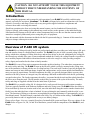
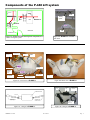
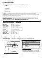
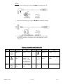
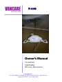
P-440 Owner’s Manual Use and Care Fault Finding Warranty Information 9$1&$5(,1& 1515 1ST STREET, AURORA, NE 68818 P 800-694-4525 F 402-694-3994 [email protected] | www.vancare.com Table of Contents P-440 Lift Introduction........................................................................................... 3 Overview ................................................................................................ 3 Components of lift system ............................................................... 4 Component List.................................................................................... 5 Specifications....................................................................................... 5 Cautions ................................................................................................. 7 Operation Turning the lift ON/OFF............................................................... 8 Raising/lowering the carry bar................................................. 9 Moving the lift along the track ................................... 10 Mounting the lift to the track .................................................11 Basics in transferring an individual.............................................12 Charging the lift .................................................................................14 Emergency Lowering........................................................................15 Emergency Stopping and Shut-Off ……………...………………….15 Attaching the airline to the lift .....................................................16 Cleaning, Disinfection and Sterilization ...................................17 Turning the Hooks Upwards .........................................................17 Fault finding ........................................................................................18 General inspection and maintenance.........................................19 Lift accessories .................................................................................20 Service record history .....................................................................21 Warranty ...............................................................................................25 P440 Lift- User Guide Rev: 2/06/09 Page: 2 CAUTION: DO NOT ATTEMPT TO USE THIS EQUIPMENT WITHOUT FIRST UNDERSTANDING THE CONTENTS OF THIS MANUAL. Introduction Before using this equipment, and to ensure the safe operation of your P-440 lift carefully read this entire manual, especially the section on “Cautions”. The P-440 is designed to be used in conjunction with Vancare lift track, accessories and slings. Please refer to any user guides supplied with these components and reference them while reviewing this manual. Should any questions arise from reviewing this manual contact your local authorized Vancare dealer. Failure to comply with warnings in this manual may result in injury to the operator, or the individual being lifted/transferred. Damage to the lift and/or related components may occur. Be sure that the contents of this manual are completely understood prior to using this piece of equipment. Store this manual with the documents included with the lift system and sling (s). Contents of this manual are subject to change without prior written notice. Overview of P-440 lift system The P-440 lift is a lifting aid used by health care professionals and those providing care in the home to lift, position and transfer clients or a disabled family member. The P-440 lift is part of what is termed ceiling lift technology which takes advantage of lifting from above and not from below or the side. Additionally the ceiling lift does not take up valuable floor space as most traditional methods do. Finally, the ceiling lift makes it possible to move mobility impaired individuals with minimal strain or risk to the caregiver, while providing complete safety, dignity and comfort for the client or family member. The P-440 lift is one of four major components that make up this technology. The other three components are the track, trolley and sling. The P-440 lift runs on the lift track which is securely mounted to the ceiling structure of the institution, or home with the use of ceiling brackets. The track itself is made of specially designed aluminum and comes in many different shapes, lengths and configurations, and is custom tailored and installed to meet your specific requirements. The third component, the sling, is a specially designed fabric accessory that attaches to the lift by means of a integral carry bar and straps, and holds an individual while the lift, positioning or transfer takes place. The fourth component, the trolley, is mounted inside the track and has wheels that allow the lift to move along the track. The lift attaches to the trolley by means of the eyelet of the trolley. The track, trolley and sling are supplied with the lift at the initial time of purchase. The P-440 lift is a portable ceiling lift. It is designed to be easily moved from one track location to another. Track are typically installed in the bedroom, bathroom and/or the living room. The P-440 lift has the ability to lift an individual up from one location such as bed, move the individual along the track to another location and finally lower the individual into a chair or bathtub. It is moved along the track manually with the aid of a caregiver. The functions of lifting up or down are accomplished by pressing the buttons of a pneumatically (air) operated hand control. The hand control is attached to the lift by way of a rubber airline tubing. The P-440 lift is powered by batteries and it is supplied with an easy to use battery charger. Please refer to figure 1A to see a sample floor plan of an installed lift system and figure 1B to see a photo of the P-440. Refer to figures 2A, 2B, 3A and 3B to familiarize yourself with the components of the P-440 lift, and charger. P440 Lift- User Guide Rev: 2/06/09 Page: 3 Components of the P-440 Lift system BATH Track Trolley eyelet BATHROOM LIFT BED TRACK #1 TRACK #2 Lift BEDROOM CUPBOARD Figure 1A - Sample floor plan showing basic components of a portable ceiling lift system. CARRY BAR HANDLE CARABINER HOOK LIFT TAPE Figure 1B - P-440 Lift mounted onto track CARRY HANDLE HAND CONTROL GROMMET POWER “ON” AND LOW BATTERY LIGHT UP BUTTON “DC” CHARGER CONNECTION DOWN BUTTON AIRLINE TUBE EMERGENCY LOWERING BUTTON EMERGENCY SWITCH Figure 2A - Front View of P-440 lift Figure 2B - Back view of P-440 lift Plug Indicator light Charger “DC” output plug Charger “AC” wall plug Figure 3B - Charger for P-440 lift Figure 3A - Charger for P-440 lift P440 Lift- User Guide Rev: 2/06/09 Page: 4 Component List The following components are included with your new P-440 lift system: • P-440 lift • Pneumatic Hand Control • Lift Charger • Owner’s Manual • Warranty Card SLINGS: If a sling has been supplied with the lift refer to the instructions included with the sling. ACCESSORIES: If additional accessories such as a turntable, or gate system, have been supplied with the lift refer to the instructions included with those items. IMPORTANT: Before initial use, the lift unit must be charged for 5 hours. Refer to section titled "Charging Instructions". The hand control airline tube must also be connected to the lift. If it is not connected refer to the section titled “Attaching the airline to the lift”. Specifications of P-440 lift 24 VDC 100-240 VAC, 0.35 Amps 29.4 VDC, 0.5 Amps 24 VDC (2 x 12 VDC) 2.3 AH Flame Retardant ABS Pneumatic – Piston Displacement Up to 1.96m 10.5 lbs (4.8 kg) 440 lbs (199.5 kg) Internal Fuses: Duty Cycle: Rated Performance: 15 Amp 1 min “ON”, 9 mins “OFF” 5-10 lifts at 440 lbs, 10% duty cycle, each lift being 24 inches at the 15.70” Models Table for P-440 Lifts 479 mm 95” Lifting Range P440 Lift- User Guide Description 303070 P-440 lift including charger and pneumatic hand control 18.83” 2005 mm 79” 2413 mm 6.38” Code 162 mm 399” mm Lift Motor: Charger Input: Charger Output: Batteries: Lift Case: Hand Control: Lifting Range: Lift Weight: Maximum Load: Shipping/Storage Conditions: Temperature: Shipping/Storage: -40 to +70 ºC Relative Humidity: Shipping/Storgage: 10 to 100% RH Atmospheric Pressure: Shipping/Storage: 500 to 1060 hPa Rev: 2/06/09 Page: 5 NOTES: • Please use the following type of plug for P-440 lifts installed in the UK: • Please use the following type of plug for P-440 lifts installed in Australia. • The P-440 lift shall be connected to a center-tapped single phase supply circuit when users in the United States connect the equipment to a 240 V supply system. Glossary of Symbols used in the P-440 Mark Symbol X X Reference Title Mark IEC 604175172 C LASS II equipment X ISO 70000434 Caution risk of danger or Attention, consult X Symbol Reference Title IEC 604175840 T YPE B APPLIED IEC 604175010 “ON” / “OFF” (pushpush) PART ACCOMPANYING D OCUMENTS X P440 Lift- User Guide IEC 604175172 C LASS II equipment Rev: 2/06/09 Page: 6 Cautions ● The P-440 must be installed prior to use. Contact your local authorized dealer to ensure that it is properly installed. The P-440 must be installed only by persons authorized by Vancare. ● Under no circumstance should the track, lift and sling (s) or entire system be put in control of a person who has not been properly trained in the use and care of this equipment. Failure to adhere to this warning may result in serious injury to the operator, and/or the individual being lifted/transferred. ● The P-440 lift and associated track and sling (s) are not toys. Do not use them for unsafe practices. Do not allow children to play with the lift or any of its components. ● The manufacturer's warranty is void if persons unauthorized by Vancare perform work on the P-440 lift system. ● There are no user serviceable parts inside the cover. Do not remove cover screws, or open the lift unit, as this will VOID THE WARRANTY. ● In facilities where more than one operator will be responsible for using the P-440 associated track and sling (s) it is imperative that all such members be trained in its’ proper use. A training program should be established by the facility to acquaint new operators with this equipment. ● Never expose the P-440 directly to water. Warranty does not cover any misuse or abuse of the lift system . ● To maintain optimum function, the P-440 should be inspected and maintained on a regular basis. See the section titled “General Inspection and Maintenance”. ● Any accessories used with the P-440, including track and sling (s), should be checked to ensure that they are in good working order. Check for signs of wear or fraying prior to use. Report any unusual wear or damage immediately to your local authorized dealer. ● The P-440 and associated lift, track and sling (s) are intended only for lifting and transferring of a person. Vancare will not be responsible for any damage caused by the misuse, neglect or purposeful destruction of the lift and/or its’ associated components. ● Do not in any circumstance exceed the maximum load of this lift. Refer to the “Specifications” section of this manual, and/or the labels on the side of the lift. ● The installation of the lift, track, accessories, and sling are certified to a maximum load. Do not exceed the maximum rated load of any of the components. ● There is a risk of explosion if the lift is used in the presence of flammable anaesthetics. ● Ensure that a clear space is maintained around the lift and track. Remove all curtain material and other obstacles out of the way before performing a transfer. P440 Lift- User Guide Rev: 2/06/09 Page: 7 Operation Caution: Always, before using the P-440 lift system, the lift, track and sling (s) must be visually checked for any unusual wear and tear. Refer to the user manual with each piece of supplied equipment to determine what should be checked. Should anything look unusual then contact your local dealer prior to use. Failure to comply with this caution could result in serious injury to the operator, the individual being lifted and/or damage to the lift. Turning the lift ON/OFF UP DOWN UP DOWN To operate the lift it must first be turned ON. This can be done in several ways. The first method is to press the blue UP or DOWN buttons located in the middle front side of the lift. When this is done the ON/OFF indicator light located on the front left side of the lift will turn GREEN indicating that the lift is ON. Refer to figures 4B and 4C. An alternative method is to press either the Grey UP or DOWN buttons on the hand control. Refer to figure 4A. When this is done the ON/OFF indicator light located on the front left side of the lift will turn GREEN indicating that the lift is ON. Refer to figure 4B. To conserve battery power the lift will automatically shut off after approximately 2 minutes of non-use. However, it is recommended that the lift be turned off when not in use. Figure 4A - Methods to Turn the P-440 “ON” The light will turn ORANGE on the lift control panel and a slow beeping audible alarm will sound if the batteries are low and require charging. Complete the transfer that is in progress and then move lift to the end of the track where the charger is located. Following the ORANGE indicator, the light will turn RED on the lift control panel and a fast beeping audible alarm will sound indicating the batteries are fully discharged and require charging. When the battery is discharged the UP function will be disabled. The DOWN and EMERGENCY DOWN function will continue to operate. See figure 4D. When the lift is connected to the charger and turned ON, the indicator light on the lift will FLASH ORANGE . This indicates that the lift is on charge. After one hour, the lift may be used, however, overnight charging is recommended. During charging the UP/DOWN functions will be disabled. The EMERGENCY DOWN function will continue to operate. Low battery indicator: Low – ORANGE and slow beeps Very Low —RED and fast beeps Figure 4B - The indictor light of the lift is normally off when not in use. P440 Lift- User Guide Figure 4C - When the lift has been turned “ON”, the indicator light will turn green. Rev: 2/06/09 Figure 4D - If the indicator light is ORANGE or RED in color then the batteries of the lift are low and should be charged. Page: 8 Operation Raising/lowering the lift By pressing the DOWN arrow button, or the UP arrow button, the lift can be lowered or raised to the correct height for attaching the sling or positioning an individual. Refer to figure 5A and 5B UP It is recommended that the caregiver (operator) steady the lift with one hand when it is close to the individual in the sling so that it will not accidentally sway and bump the individual or close object. DOWN Figure 5A - Hand control Figure 5B - Lift will move up and down the strap when the UP/DOWN buttons are pressed. Alternatively, located in the middle front side of the lift unit is a panel that has UP and DOWN buttons. By pressing the DOWN arrow button, or the UP arrow button, the lift can be lowered or raised to the correct height for attaching the sling or positioning an individual. Refer to figure 5C. UP DOWN Figure 5C - Hand control showing raising/lowering buttons P440 Lift- User Guide It is recommended that the caregiver (operator) steady the lift with one hand when it is close to the individual in the sling so that it will not accidentally sway and bump the individual or close object. Rev: 2/06/09 Page: 9 Moving the lift along the track The lift can be easily moved along the track by simply pushing it by hand. For ease of use it is recommended that the lift be first lowered to a comfortable height at which it can easily be pushed along the length of the track by hand. Care must be taken when moving the lift along the track. Ensure that the lift or the individual in the sling of the lift does not come into contact with any objects such as desks, counters, walls, etc.. Use the carry bar handle to push the lift along the track Caution: Always be cautious when moving an individual along the track. Watch out for and avoid any obstructions that may cause injury to the individual in the sling or damage to the lift. Figure 6A - The lift is moved along the track manually, by pushing it with the hand. The trolley located inside the track will glide the lift along. The lift moves along the track by means of a trolley assembly that is mounted inside the track. Each track location will have one of these trolleys installed. Trolley set Trolley eyelet The eyelet of the trolley hangs down below the track and provides the way of connecting the lift to the track. The wheels of the trolley are designed to move the lift along the track with very little effort. Track Figure 7A - Photo showing the lift trolley that is installed along the inside of the track. The eyelet of the trolley connects to the hook of the lift in one of several ways. P440 Lift- User Guide Rev: 2/06/09 Page: 10 Mounting the lift to the track The first step in being able to use the P-440 lift is to mount it onto the trolley of the lift track. There are several ways of making this connection. Refer to figures 8A through to 11B to determine the type of ceiling connection that has been installed with the purchased system. Caution: Always check to ensure that the lift hook is attached properly to the eyelet of the trolley, or the reacher, or the lanyard. The safety latch of the lift hook must always be in a locked position as shown in the close-up photos 8B, 9B, 10B and 11A. Option 2 - Connection with reacher Option 1 - Direct connection to trolley Trolley Eyelet of trolley Reacher Eyelet of trolley Reacher Arm Lift hook Lift Hook Figure 8A - Photo showing connection of lift hook directly to the eyelet of the trolley. Figure 8B - Photo showing closeup of lift hook connected directly to eyelet of trolley. Option 3 - Connection with lanyard Figure 9A - Photo showing P-440 lift carabioner connected to a reacher first and then to the eyelet of the trolley. Figure 9B - Photo showing close up of P-440 lift carabioner connected to a reacher first and then to the eyelet of the trolley. Option 4 - Connection with lanyard and Reacher arm Carabiner. Eyelet of trolley Lanyard Lanyard Lanyard Carabiner Lift Hook Figure 10A - Photo of lift hook connected to a P-440 lanyard first and then to the eyelet of the trolley. P440 Lift- User Guide Figure 10B - Photo showing close-up of lift hook, lanyard and eyelet of trolley. Rev: 2/06/09 Figure 11A - Photo showing lift hook connected to a reacher & lanyard and finally to the eyelet of the trolley. Page: 11 Basics in transferring an individual Caution: The following steps are intended to generally describe the procedure involved in the lifting and transferring of an individual from one location to another using the lift, track and sling. Track configurations will vary by installation. The manual for the sling that was purchased with the lift should be reviewed in detail prior to attempting these steps. Contact your local authorized dealer should you have any questions or concerns. Step 1) Carry the P-440 Lift to the desired transfer location. Set it on a secure object such as a table or chair. Let sufficient strap out of the lift so that the lift hook can be easily attached to the eyelet of the trolley without having to lift the lift. Attach the lift hook to the eyelet of the trolley as noted in the previous section titled “Mounting the lift to the track”. Lower the lift to a comfortable level so that it can easily be moved. Move it close to the individual that is to be transferred. Use the procedures for up and down and moving along the track as described in the previous sections titled “Raising/Lowering the lift” and “Moving the lift along the track”. Caution: Always be cautious when raising or lowering the lift, or moving the lift along the track. Watch out for and avoid any obstructions that may cause injury to the lift. Step 2) Prepare the individual being transferred with the appropriate sling. Refer to the instructions supplied with the sling that was purchased on how to properly outfit an individual with a sling. Caution: Always make sure that the sling is correctly fitted and adjusted on each side of the individual so that maximum comfort and safety are achieved prior to lifting. Refer to the sling instructions that were supplied with the sling. Step 3) Once the individual has been outfitted with the sling, move the lift so that it is positioned directly over the individual. The lift may need to be raised or lowered, or re-positioned along the track in order to accomplish this. Lower the lift so that the integral carry bar hooks are at a height that makes connecting the straps of the sling easy to accomplish. Steady the lift with one hand so that it does not accidentally come in contact with the head or body of the individual to be lifted. Caution: Always check to ensure that when the lift is lowered that it does come in contact with the person being lifted. Steady the lift with one hand while it is being lowered near an individual. Caution: Always check to ensure that the lift is correctly positioned directly above the person to be lifted. Over time, the lift strap may fray if this is not followed. Step 4) Following the instructions provided with the sling. Attach the straps of the sling to the carry bar handles of the lift. The straps on each side of the sling are generally attached to the corresponding side of the carry bar hooks. Be sure to double check to ensure that the straps are properly attached to the carry bar hooks, and that the individual being lifted is properly positioned in the sling prior to lifting. Caution: Prior to lifting an individual make sure that the straps of the sling are securely placed on the carry bar and that the straps will not come off . Step 5) The individual may now be raised with the use of the UP button on the hand control or front panel but- ton. While lifting is in progress the height required in order for the transfer to be completed should be closely observed. Ensure that the individual being lifted will not be injured by any obstructions during the initial lifting. P440 Lift- User Guide Rev: 2/06/09 Page: 12 Basics in transferring an individual … continued Step 6) Once at the correct height the individual can be moved along the track to the desired location. Caution: Always be cautious when moving an individual along the track. Watch out for and avoid any obstructions that may cause injury to the lift or individual in the sling. Step 7) Once at the desired location the individual in the sling can be lowered/raised to the correct height in order to complete the transfer. On completion of lowering/raising ensure that the individual is properly positioned and safely supported prior to removing the straps of the sling. Caution: Always be cautious when lowering/raising an individual who is in the sling of the lift. Watch out for and avoid any obstructions that may cause injury to the individual. Step 8) Lower the lift sufficiently to allow the sling straps to be easily removed taking care not to let it come in contact with the individual in the sling. Caution: Prior to removing the sling straps from the carry bar hooks be sure to check that the individual is securely and safely supported in the final desired position. Step 9) The straps of the sling can now be removed from the carry bar hooks. The sling can then be removed from the individual and stored in a safe place until next use. Step 10) The lift should now be raised sufficiently and moved away from the immediate area of the individual that was transferred. The lift should be turned off . Step 11) The lift can now be removed from track, relocated to another track, or stored in a safe place until next use. It is recommended that the lift be charged when not in operation. Refer to the section titled “Charging the lift” for details on charging. Caution: Always use extreme care when removing the lift from the track. Lower the lift such that it is securely resting on a stable object such as a dresser, cart or table prior to removal. Use extreme care when re-locating the lift. Be sure it is securely held during transport. Optional Hand Control Hook Your lift has come with an optional Hand Control Hook. This Hand Control Hook can be installed onto the Hand Control using the self tapping screws provided with the plastic hook. On the back of the Hand Control there will be 2 small pilot holes where the self tapping screws should be screwed into. See figure 11C and 11D for a Hand Control with the Plastic Hook already assembled. Figure 11E demonstrates the use of the hook with your lift. Figure 11C - Hand Control with Hook P440 Lift- User Guide Figure 11D - Hand Control with Hook Rev: 2/06/09 Figure 11E - Suggested use Page: 13 Charging the lift The batteries of the lift should be charged on a regular basis. It is recommended that the lift be left on charge when not in operation, and at the end of each day. This will maximize the life cycle of the batteries. “DC” charger connection Lift Charger “DC” lift plug The lift may remain connected to the charger indefinitely since the charger has a built-in regulator, eliminating the danger of overcharging. Step 1) Familiarize yourself with the basic components of the charging system. Refer to figures 12A and 12B. Charger “AC” wall cord harger Charger Figure 12A - P-440 lift and charger set on a secure table top or counter for charging. Plug Indicator light Charger “DC” output plug Step 2) Place the lift and charger on a safe surface such as a table or counter top. The surface must be clean and dry, and away from the reach of a child. Step 3) Turn the lift ON as described in the section titled “Turning the lift ON/OFF”. Step 4) Plug the charger “AC” wall plug into a nearby wall outlet. The indicator light on the charger will turn GREEN. Charger “AC” wall plug Caution: Do not use an electrical extension to extend the reach of the “AC” wall plug. Step 5) Take hold of the charger “DC” output plug and visually observe that it has three (3) prongs inside of its metal case. These are designed to fit into the three (3) holes that are located on the black lift “DC” connection. Refer to figure 12C. Figure 12B - Charger for P-440 lift Lift “DC” charger connection Step 6) Take the charger “DC” output plug and connect it to the black lift “DC” connection being careful to ensure that the metal prongs from the charger plug fit into the holes of the black lift connector. When this is completed correctly, then the indicator light on the charger will turn ORANGE. Refer to figures 12D, E. “DC” Charger output plug Figure 12C - Close-up of “DC” charger plug and lift “DC” charger connection. Note the 3 metal prongs on the end of the charger cord and 3 holes on the black “DC” connection. Figure 12D - Connect the charger to the lift. Be sure to line up the 3 metal prongs on the end of the charger with the 3 holes in the black lift “DC” connection. Caution: Do not operate the lift while it is connected to the charger. Figure 12E - Charger is connected to the lift. The indicator light on the charger will be ORANGE indicating that the lift is charging. After a minimum of 1 hour the charger can be disconnected from the lift, and the lift put into use. However overnight charging is recommended. Caution: The charger must be located outside the patient vicinity at all times. The patient vicinity is the space with surfaces likely contacted by the patient or an attendant who can touch the patient. This space is 6 feet (1.83m) beyond the perimeter of the bed, examination table, etc., extending vertically 7-1/2 feet (2.29m) above the floor. P440 Lift- User Guide Caution: Do not allow the batteries to become discharged below the low battery alarm, as this will decrease overall battery life and performance. Caution: Use only the charger that was supplied with the lift. Use of any other charger will void all warranties and may cause damage to the lift. Rev: 2/06/09 Page: 14 Emergency Lowering The DOWN blue button located on the front right side of the lift can be used to lower an individual should the hand control buttons fail. Refer to figure 14B. Figure 14A –Lift showing DOWN button located on front right side of lift. Figure 14B –RED emergency lowering button located on middle of the front of the lift. Should both DOWN arrow buttons on the hand control, and the DOWN button of the lift fail, the person may be lowered by pressing the RED emergency lowering button located on middle front side of the lift. There will be a delay of approximately 2 seconds before the lift starts to lower. An audible alarm will also sound during the emergency lowering. Refer to figure 14B. IMPORTANT: The Emergency Lowering system does not provide a raising function. The failure of any of the lowering device should be reported to your authorized dealer immediately. Emergency Stopping and Shut-off The lift normally shuts off if the lift has not been in use for 2 minutes. Should a situation present itself such that the lift will not respond to the hand control buttons or on any of the normal operational control buttons on the front of the lift then the RED Emergency stop switch should be switched to the “OFF “ position. This will shut off power going to the motor of ON/OFF button on lift Figure 14C –RED Emergency stop switch located on the front left side of the lift. ON Emergency OFF/STOP Figure 14D - Close-up of switch ON - Normal lift Operation OFF - Emergency Stop P440 Lift- User Guide the lift and will immediately stop all movement. Should the emergency stop function be used in an emergency, then before the lift can be used again, it must be inspected by an authorized dealer. Once the lift has been inspected and/or repaired, then the Emergency Stop Button can be set to the “ON” position. Normal use of the lift may then proceed. Note: The lift will only charge if the Emergency stop switch is in the “ON” position. Refer to the section titled, “Charging the lift” for charging instructions. Rev: 2/06/09 Page: 15 Attaching the airline tube to the lift Should the gray rubber airline that connects the lift to the hand control become disengaged from the front left side of the lift it must be re-connected in order for the lift to work properly. The rubber airline may become disconnected for the following reasons: Figure 15A - Gray rubber grommet located on front right side of the lift. Rubber airline is not connected. Note ridge on grommet. 1) The lift is pulled along the track by the airline. 2) The tubing accidentally gets wrapped around an object while a lift or transfer is being performed. 3) It is accidentally pulled out by the caregiver or the individual being lifted. The airline is connected to a gray rubber grommet located on the front left side of the lift. Refer to figure 15A. Small metal ribbed pins located at the end of the airline hold the airline to this rubber grommet in a specific manner. Therefore it is important to make sure that the airline is connected properly. Metal pins get inserted into the holes of the grommet of the lift. Figure 15B - Gray rubber airline being inserted into rubber grommet of lift. The ridges on both pieces are lined up. The metal ribbed pins are on the airline (within the shroud). Both the gray airline and the rubber grommet have a ridge on one of their sides. Align the ridges for proper connection. Refer to figure 15B. When this is done then the metal ribbed pins attached to the end of the airline can be re-insert into the corresponding holes in the rubber grommet located on the front left side of the lift. Be sure to insert the pins into the gray rubber grommet sufficiently so that it is secure. Refer to figure 15C. Perform a brief test of the lift to ensure proper connectivity. Turn the lift ON and OFF. Raise and lower the lift. If the lift does not work properly, check to ensure that the ridges on the gray rubber grommet on the underside of the lift and the airline tubing are lined up properly. If they are not lined up properly, then remove the airline, line up the ridges and then re-insert it into the rubber grommet. Perform the test as noted in the preceding paragraph. If there are still problems with the lift then contact your local authorized dealer for service. Pieces connected together Figure 15C - Gray rubber airline being inserted into rubber grommet of lift. The ridges on both pieces are lined up. The metal ribbed pins are on the airline. P440 Lift- User Guide Rev: 2/06/09 Page: 16 Cleaning, Disinfection and Sterilization The exterior of the lift should only be cleaned, disinfected and sterilized using isopropyl alcohol. Damp a cloth with isopropyl alcohol and wipe down entire exterior of lift including strap and hook. No other chemicals and/or liquids should be used to clean, disinfect and sterilize this lift. Caution: Take great care to ensure that no liquids get inside the lift. This lift is not drip proof or water tight. Failure to protect the lift from liquids may result in damage to the lift and/ or may cause personal injury. Turning the hooks upwards The P-440 has a feature that allows for the hooks to be turned upwards as shown. This may be used for transporting or storing the lift. Figure 16A - P-440 with hooks in normal positioin Figure 16B - P-440 with hooks turned upwards. P440 Lift- User Guide Rev: 2/06/09 Page: 17 Fault Finding Should problems arise with the use of the P-440 lift review the following chart. Find the fault and complete the recommended solution. If the fault is not found and/or the solution does not correct the problem contact your local authorized dealer for service immediately. Fault Recommended Solution The airline tubing that connects the hand control to the lift has become disengaged. Refer to the section of this manual titled “Attaching the airline tube to the lift”. If this does not correct the problem then contact your local authorized dealer immediately so that the lift can be checked to ensure proper continued operation. The hand control buttons do not operate according to their designations (e.g. the UP button initiates a down movement). The airline tubing has not been connected correctly. Refer to the section of this manual titled “Attaching the airline and hand control to the lift”. If this does not correct the problem then contact your local authorized dealer immediately so that the lift can be checked to ensure proper continued operation. The lift does not operate up or down even when the airline has been properly connected. The indicator light on the front right side of the lift should be GREEN. Press the ON/OFF button or UP/DOWN arrow buttons on the hand control. This should activate the lift and the indicator light turn GREEN. If the lift still does not function, then the batteries may be low and require charging. Refer to the section of this manual titled “Charging the lift”. Charge the lift for at least one hour and then try to raise and lower it. The GREEN light on the left front There is a built-in slack tape detector in the lift. This may be sensitive. Take hold of the lift side of the lift is ON and the lift does strap about 10 centimetres above the top of the lift and pull it upwards in order to tighten the not operate in the DOWN direction. lift strap, and then press the DOWN button. If this corrects the problem temporarily but not permanently then contact your local authorized dealer so that the lift can be checked to ensure proper continued operation. The red indicator light on the left The batteries are low and require charging. Refer to the section of this manual titled front side of the lift turns RED and/or “Charging the lift”. Charge the lift for at least one hour and then try to raise and lower a loud alarm sound is heard when an it. individual is raised. If this does not correct the problem then contact your local authorized dealer immediately so that the lift can be checked to ensure proper continued operation. One side of the lift tape (strap) is starting to fray after continued use. Check to be sure that the lift is always directly above the individual being lifted. Refer to the section titled “Basics in transferring an individual” for correct lift positioning. If fraying still continues then contact your local authorized dealer immediately so that the lift can be checked to ensure proper continued operation. The lift does not pass through a track Refer to the “Owners Manual” for the specific piece of equipment in question. If the recomcomponent such as a turntable or mended solution does not correct the problem then contact your local authorized dealer imgate. mediately so that the lift can be checked to ensure proper continued operation. P440 Lift- User Guide Rev: 2/06/09 Page: 18 General Inspection and Maintenance A) Each Use - To be completed by User Prior to each use the P-440 lift and associated track, accessories and sling (s), must be visually inspected. Refer to the accessory and sling user guides for specific details regarding their inspection. Should any of the these items fail the inspection do not use the lift Contact your local authorized dealer for service. Visually check for the following: The lift strap shows NO signs of fraying or breaking along its entire length. □ □ The stitching on the lift strap where it connects to the lift hook shows NO signs of fraying or breaking. □ The sling (s) that will be used show NO signs of unusual wear or damage. The straps of the sling that □ □ □ □ □ □ □ connect to the carry bar hooks of the lift show NO signs of fraying or breaking. The airline tube that connects the hand control to the lift is not kinked, twisted, knotted, cut or damaged. All the functions on the hand control work correctly (e.g. UP/DOWN). The brackets that hold the track in place on the ceiling are secure and do not move or appear loose. The lift has no unusual sounds when it is moved UP/DOWN or along the track.. Ensure that there are end stops installed at each end of the track. There are not cuts, dents or sharp edges on the carry bar hooks that may damage straps of the sling. The carabiner hook shall be visually inspected before and after each lift for damages. B) Monthly - To be completed by User Should any of the these items fail the inspection do not use the lift. Contact your local authorized dealer for service. □ Complete the visual inspection as noted in the “Each Use” section above. With no one in the sling nor attached to the lift check the following: □ The lift moves freely along the entire length of the track. C) Semi-Annual or Yearly - To be completed by a lift technician Consult your local authorized dealer for advice on whether this section should be completed every 6 months or on a yearly basis. Generally, in frequent use, or in situtations where heavier than normal clients are lifted, or in multi-user environments such as in institutions the lift should be checked every 6 months. This section to be only completed by a qualified service technician as authorized by 9DQFDUH □ □ Complete the visual inspection as noted in the “Monthly” section above. Lift checked and passed. Any required repairs completed. P440 Lift- User Guide Rev: 2/06/09 Page: 19 Lift Accessories The following is a list of available accessories for the P-440 lift. Items such as the track, turntables and brackets are installed at the time of purchase. Add-on pieces are available to after the initial purchase, however your local authorized dealer must be consulted as to suitability, purchase and installation. Slings are the most common after purchase accessory. A variety of styles, sizes, and colors are available. Custom slings can also be manufactured to meet special needs. Consult your local authorized dealer for details, pricing and a complete list of current sling models. TRACK 1.82MTR (6FT) LENGTH 2.5MTR (8FT) LENGTH MAY BE CUT AT TIME OF INSTALLATION TRACK 5.0MTR (16FT) LENGTH MAY BE CUT AT TIME OF INSTALLATION TRACKPLUS TRACK 5.0MTR (16FT) LENGTH 6.0MTR (19FT) LENGTH MAY BE CUT AT TIME OF INSTALLATION TRACK TRANSGATE SYSTEM 90 DEGREE CURVE MAY BE CUT AT TIME OF INSTALLATION TRACK 45 DEGREE CURVE MAY BE CUT AT TIME OF INSTALLATION TRACK END STOP "H" SYSTEM TROLLEY SET USED ONLY WITH "H" FRAME AREA COVERING SYSTEM MULTI-PORT TURNTABLE SYSTEM WALL MOUNT BRACKET 3" TRACK BRACKET REACHER VARIOUS STYLES AND SIZES OF SLINGS. CUSTOM SLINGS AVAILABLE. QUICK FIT TURNTABLE SYSTEM 6" TRACK BRACKET EXTENDED CARRY BAR ACCESSORIES NOT TO SCALE. FOR ILLUSTRATIVE PURPOSES ONLY. NOTICE: ACCESSORY SIZE, STYLE, SHAPE, LENGTH, CONFIGURATIONS, OPTIONS, COLOURS AND SPECIFICATIONS MAY CHANGE WITHOUT PRIOR WRITTEN NOTICE. CONTACT YOUR LOCAL AUTHORISED DEALER FOR DETAILS. CAUTION: ONLY SLINGS AUTHORIZED BY 9$1&$5( ARE TO BE USED WITH THIS LIFT. CONTACT YOUR LOCAL AUTHORIZED DEALER FOR DETAILS. P440 Lift- User Guide Rev: 2/06/09 Page: 20 Service Record History - Initial Information • • • • Complete the following section on Purchase and Service Information as soon as this equipment is installed. Use the service record history to record to any completed service and repairs. Ensure that the service record is signed and dated each time it is used. Be sure to have this piece of equipment serviced on a regular basis as described in the General Inspection and Maintenance Section PURCHASE INFORMATION: Product Name: P-440 lift Model: ____________________________ Serial#:________________________ Date of Purchase: _____________________ Date Installed: _________________ Purchased From: ______________________________ _____________________________ Address: ____________________ ___________________ City: __________________________ Telephone No: __________________________ Postal Code: __________________ Comments: SERVICE INFORMATION: Contact the following company for service: Company: ______________________________ Address: ____________________ _____________________________ ___________________ City: __________________________ Telephone No: __________________________ Postal Code: _________________ Comments: P440 Lift- User Guide Rev: 2/06/09 Page: 21 Service Record History Date: _______________________ Service Type: □ Periodic Inspection Complete this section after each service, repair inspection and/ or maintenance. Photocopy additional pages as required. Time: ________________________ □ Monthly Inspection Completed By: _________________________ Printed Name □ 6 Month Inspection □ Repair □ Yearly Inspection □ Other:_________ _____________________________ Signature Company: _____________________________________________________________ Remarks & Action Taken: Date: _______________________ Service Type: □ Periodic Inspection Time: ________________________ □ Monthly Inspection Completed By: _________________________ Printed Name □ 6 Month Inspection □ Repair □ Yearly Inspection □ Other:_________ _____________________________ Signature Company: _____________________________________________________________ Remarks & Action Taken: Date: _______________________ Service Type: □ Periodic Inspection Time: ________________________ □ Monthly Inspection Completed By: _________________________ Printed Name □ 6 Month Inspection □ Repair □ Yearly Inspection □ Other:_________ _____________________________ Signature Company: _____________________________________________________________ Remarks & Action Taken: Date: _______________________ Service Type: □ Periodic Inspection Time: ________________________ □ Monthly Inspection Completed By: _________________________ Printed Name □ 6 Month Inspection □ Repair □ Yearly Inspection □ Other:_________ _____________________________ Signature Company: _____________________________________________________________ Remarks & Action Taken: Date: _______________________ Service Type: □ Periodic Inspection Time: ________________________ □ Monthly Inspection Completed By: _________________________ Printed Name □ 6 Month Inspection □ Repair □ Yearly Inspection □ Other:_________ _____________________________ Signature Company: _____________________________________________________________ Remarks & Action Taken: Date: _______________________ Service Type: □ Periodic Inspection Time: ________________________ □ Monthly Inspection Completed By: _________________________ Printed Name □ 6 Month Inspection □ Repair □ Yearly Inspection □ Other:_________ _____________________________ Signature Company: _____________________________________________________________ Remarks & Action Taken: P440 Lift- User Guide Rev: 2/06/09 Page: 22 Service Record History Date: _______________________ Service Type: □ Periodic Inspection Complete this section after each service, repair inspection and/ or maintenance. Photocopy additional pages as required. Time: ________________________ □ Monthly Inspection Completed By: _________________________ Printed Name □ 6 Month Inspection □ Repair □ Yearly Inspection □ Other:_________ _____________________________ Signature Company: _____________________________________________________________ Remarks & Action Taken: Date: _______________________ Service Type: □ Periodic Inspection Time: ________________________ □ Monthly Inspection Completed By: _________________________ Printed Name □ 6 Month Inspection □ Repair □ Yearly Inspection □ Other:_________ _____________________________ Signature Company: _____________________________________________________________ Remarks & Action Taken: Date: _______________________ Service Type: □ Periodic Inspection Time: ________________________ □ Monthly Inspection Completed By: _________________________ Printed Name □ 6 Month Inspection □ Repair □ Yearly Inspection □ Other:_________ _____________________________ Signature Company: _____________________________________________________________ Remarks & Action Taken: Date: _______________________ Service Type: □ Periodic Inspection Time: ________________________ □ Monthly Inspection Completed By: _________________________ Printed Name □ 6 Month Inspection □ Repair □ Yearly Inspection □ Other:_________ _____________________________ Signature Company: _____________________________________________________________ Remarks & Action Taken: Date: _______________________ Service Type: □ Periodic Inspection Time: ________________________ □ Monthly Inspection Completed By: _________________________ Printed Name □ 6 Month Inspection □ Repair □ Yearly Inspection □ Other:_________ _____________________________ Signature Company: _____________________________________________________________ Remarks & Action Taken: Date: _______________________ Service Type: □ Periodic Inspection Time: ________________________ □ Monthly Inspection Completed By: _________________________ Printed Name □ 6 Month Inspection □ Repair □ Yearly Inspection □ Other:_________ _____________________________ Signature Company: _____________________________________________________________ Remarks & Action Taken: P440 Lift- User Guide Rev: 2/06/09 Page: 23 Service Record History Date: _______________________ Service Type: □ Periodic Inspection Complete this section after each service, repair inspection and/ or maintenance. Photocopy additional pages as required. Time: ________________________ □ Monthly Inspection Completed By: _________________________ Printed Name □ 6 Month Inspection □ Repair □ Yearly Inspection □ Other:_________ _____________________________ Signature Company: _____________________________________________________________ Remarks & Action Taken: Date: _______________________ Service Type: □ Periodic Inspection Time: ________________________ □ Monthly Inspection Completed By: _________________________ Printed Name □ 6 Month Inspection □ Repair □ Yearly Inspection □ Other:_________ _____________________________ Signature Company: _____________________________________________________________ Remarks & Action Taken: Date: _______________________ Service Type: □ Periodic Inspection Time: ________________________ □ Monthly Inspection Completed By: _________________________ Printed Name □ 6 Month Inspection □ Repair □ Yearly Inspection □ Other:_________ _____________________________ Signature Company: _____________________________________________________________ Remarks & Action Taken: Date: _______________________ Service Type: □ Periodic Inspection Time: ________________________ □ Monthly Inspection Completed By: _________________________ Printed Name □ 6 Month Inspection □ Repair □ Yearly Inspection □ Other:_________ _____________________________ Signature Company: _____________________________________________________________ Remarks & Action Taken: Date: _______________________ Service Type: □ Periodic Inspection Time: ________________________ □ Monthly Inspection Completed By: _________________________ Printed Name □ 6 Month Inspection □ Repair □ Yearly Inspection □ Other:_________ _____________________________ Signature Company: _____________________________________________________________ Remarks & Action Taken: Date: _______________________ Service Type: □ Periodic Inspection Time: ________________________ □ Monthly Inspection Completed By: _________________________ Printed Name □ 6 Month Inspection □ Repair □ Yearly Inspection □ Other:_________ _____________________________ Signature Company: _____________________________________________________________ Remarks & Action Taken: P440 Lift- User Guide Rev: 2/06/09 Page: 24 If you have any questions about the manufacture or operation of this equipment, please contact Vancare, or your local authorized dealer. Vancare, Inc. 1515 1st Street Aurora, NE 68818 Telephone: (402) 694-4525 Fax: (402) 694-3994 Toll Free: 1-800-694-4525 P440 Lift- User Guide Rev: 2/06/09 Page: 25 P440 Portable Ceiling Lift Skills Competency Checklist Staff Member Observed________________________ Date _______________ --------------------------------------------------------------------------------Fixed Ceiling Lift: A lift unit that remains, permanently, on a given piece of ceiling lift track. Fixed lifts are used in a 1:1 ratio of lifts per track Portable Ceiling Lift: A lift unit that is shared between several pieces of track. It is recommended that portable ceiling lift units do not exceed greater than a 1:5WRGHSHQGLQJXSRQFHQVXV • The P440 Ceiling Lift can be used for which of the following types of patient care techniques? • Of the following types of slings, which can be used in conjunction with the P440 Ceiling Lift? • Bed to Chair Bed to Commode/Toilet Transporting to Communal Bathing Area Chair to Bed Floor to Bed Repositioning in Chair Repositioning in Bed Turning in Bed Sit to Stand Universal with Head Support Universal Hammock Hygiene Positioning Walking Standing Stand Aid Belt Band Sling What is the Safe Working Load of the P440 Ceiling Lift? 300 lbs. 450 lbs. 440 lbs. 625 lbs. Demonstration Component NOTE: The examiner must provide each candidate with a scenario for proper evaluation. Some points relevant to each scenario may not be reflected in the checklist below. Please feel free to add skills based on scenario. Ceiling Lift Skills Checklist Ceiling Lift/ Battery Charging Charger Indicators Low Battery Indicators Charging Procedures Pneumatic Airline Use Emergency Lowering- Manual Emergency Lowering-Electric Positioning of Lift Relative to Client Proper Assessment of Client Proper Sling Selection based on Assessment Proper Ergonomic Position while applying Sling Demonstrates Competency in proper loop/strap selection Proper Ergonomic Position while Maneuvering the Lift Proper Laundering procedures for slings Identify the color codes for size of slings Sizing slings correctly How to apply/remove slings in chair Attaching proper sling loops to lift carry bar Bed to Chair Repositioning in bed From Floor Transfer I have attended the training session for operating the mechanical lifts and have understood the above skills that have been presented to me. Observations _______________________________________________________________________________ __________________________________________________________________________________________ Observer's Name ____________________________________________________________________________ Observer's Signature_________________________________________________________________________ Vancare, Inc. 1515 1st Street Aurora, NE 68818 1.800.694.4525 www.vancare.com