1
The User
User’’s Manual of TK500
Control Board
Shenzhen Icod Digital Co., Ltd.
The manufacture has authorized to revise the
contents of this document without notice!
1
Table of Contents
ChapterⅠINTRODUCTION.............................................................................................................. 6
1.1 The characters of this product............................................................................................... 6
1.1.1 Model......................................................................................................................... 6
1.1.2 The supporting character set...................................................................................... 6
1.1.3 The print head models of the equipment linker......................................................... 6
1.1.4 The functions and applications that the printer carries out........................................ 6
1.1.5Hardware..................................................................................................................... 7
1.2The main use and applicable area.......................................................................................... 7
1.3Environmental specification.................................................................................................. 7
1.4Operation specification.......................................................................................................... 8
1.5Security................................................................................................................................... 9
Chapter II CONFIGURATION AND INSTALLATION.................................................................. 10
2.1General Configuration.......................................................................................................... 10
2.1.1The figure of control board configuration................................................................ 10
2.1.2Dimension................................................................................................................. 10
2.1.3Weight........................................................................................................................11
2.2 PCB installing method.........................................................................................................11
Chapter III SYSTEM INSTALLATION AND OPERATION.......................................................... 12
3.1 System connection.............................................................................................................. 12
3.1.1 Power connection..................................................................................................... 12
3.1.2 Interface connection................................................................................................. 13
3.1.3 Print head connection............................................................................................... 13
3.1.4 Operation board connection..................................................................................... 14
3.1.5 Paper near-end sensor connection............................................................................ 15
3.2 Interface Connection........................................................................................................... 15
3.2.1 RS-232 serial interface............................................................................................. 15
3.2.2 IEEE 1284 Bidirectional Parallel Interface..............................................................21
3.3 Panel Buttons and Indicators............................................................................................... 27
3.3.1 Panel buttons............................................................................................................ 27
3.3.2 Indicators.................................................................................................................. 27
3.4 Special operation mode....................................................................................................... 28
3.4.1 Self-test.....................................................................................................................28
3.4.2 Hex Dump................................................................................................................ 29
3.5 DIP switch and memory switch settings............................................................................. 30
3.5.1 DIP switch setting.................................................................................................... 30
3.5.2 Set memory function switch.................................................................................... 32
3.6 Error Processing.................................................................................................................. 34
3.6.1 Error type.................................................................................................................. 34
3.6.2 Operation when an error is detected........................................................................ 35
3.6.3 Data reception error................................................................................................. 35
3.7 Status test.............................................................................................................................36
3.7.1 Paper status test........................................................................................................ 36
2
3.7.2 Print head bar status test........................................................................................... 36
3.8 Notes on the BM function................................................................................................... 36
3.9 Page Mode........................................................................................................................... 37
3.9.1 Introduction.............................................................................................................. 37
3.9.2 The setting value under the normal mode and page mode....................................... 38
Chapter IV Printing Control Commands........................................................................................... 39
4.1Command Table................................................................................................................... 39
4.2 Command Introduction....................................................................................................... 43
4.2.1 Command notation................................................................................................... 43
4.2.2 Explanation of Terms............................................................................................... 43
4.3 Command Specification...................................................................................................... 45
HT...................................................................................................................................... 45
LF...................................................................................................................................... 45
FF.......................................................................................................................................46
CR...................................................................................................................................... 46
CAN...................................................................................................................................47
DLE EOT n....................................................................................................................... 47
DLE ENQ n....................................................................................................................... 49
ESC FF.............................................................................................................................. 50
ESC SP n........................................................................................................................... 50
ESC ! n........................................................................................................................ 51
ESC $ nL nH................................................................................................................ 52
ESC % n............................................................................................................................ 53
ESC & y c1 c2 〔x1 d1...d(y×x1)〕...〔xk d1...d(y×x)〕.......................................... 53
ESC * m nL nH d1...dk.................................................................................................. 56
ESC – n..........................................................................................................................58
ESC 2.................................................................................................................................59
ESC 3 n..............................................................................................................................59
ESC ? n........................................................................................................................ 60
ESC @............................................................................................................................... 60
ESC D n1...nk NUL...........................................................................................................61
ESC E n............................................................................................................................. 61
ESC G n.....................................................................................................................62
ESC J n.............................................................................................................................. 62
ESC L................................................................................................................................ 63
ESC M n............................................................................................................................ 63
ESC R n............................................................................................................................. 64
ESC S................................................................................................................................ 64
ESC T n............................................................................................................................. 65
ESC V n............................................................................................................................. 66
ESC W xL xH yL yH dxL dxH dyL dyH......................................................................... 66
ESC ﹨ nL nH................................................................................................................. 68
ESC a n.............................................................................................................................. 69
ESC c 3 n........................................................................................................................... 70
3
ESC c 4 n........................................................................................................................... 70
ESC c 5 n........................................................................................................................... 71
ESC d n..............................................................................................................................71
ESC t n............................................................................................................................... 72
ESC { n.........................................................................................................................72
FS p n m............................................................................................................................ 73
FS q n [xL xH yL yH d1...dk] 1... [xL xH yL yH d1...dk]n............................................. 74
GS FF................................................................................................................................ 77
GS ! n........................................................................................................................ 77
GS $ nL nH....................................................................................................................... 79
GS ( A pL pH n m....................................................................................................... 80
GS ( E pL pH m................................................................................................................ 81
GS ( E pL pH m d1 d2(when m=1)...................................................................................81
GS ( E PL PH m [m1 b18..b11]..[ak bk8..bk11] (when m=3).......................................... 82
GS ( E pL pH m a (when m=4)......................................................................................... 83
GS ( pL pH a m nL nH...................................................................................................... 84
GS ( K pL pH n m.................................................................................................... 85
GS ( K pL pH n m (when n=480<function 48>................................................................ 86
GS ( K pL pH n m (when n=49)<function 49>................................................................ 86
GS ( M pL pH a n m.......................................................................................................... 87
GS ( M pL pH n m (n=1,49) <function 1>........................................................................88
GS ( M pL pH n m (n=2, 50) <function 2>....................................................... 88
GS ( M pL pH n m (n=3, 51)<function 3>........................................................................89
GS * x y d1...d(x y 8)................................................................................................ 90
GS / m......................................................................................................................91
GS :............................................................................................................................... 92
GS B n............................................................................................................................... 92
GS C 0 n m........................................................................................................................ 93
GS C 1............................................................................................................................... 93
GS C 2 nL nH.................................................................................................................... 94
GS C; sa; sb; sn; sr; sc;......................................................................................................95
GS H n............................................................................................................................... 96
GS I n.................................................................................................................................97
GS L nL nH....................................................................................................................... 98
GS T n..................................................................................................................... 98
GS V m ②GS V m n........................................................................................................ 99
GS W nL nH.................................................................................................................... 100
GS ﹨ pL pH..................................................................................................................101
GS ^ r t m......................................................................................................................... 102
GS a n......................................................................................................................... 102
GS b n.................................................................................................................... 106
GS c................................................................................................................................. 106
GS f n.............................................................................................................................. 107
GS h n.................................................................................................................... 107
4
GS k m d1...dk NUL ②GS k m n d1...n................................................................... 107
GS r n............................................................................................................................... 111
GS v 0 m xL xH yL yH d1...dk............................................................................... 112
GS w n............................................................................................................................. 114
4.4Chinese control command.................................................................................................. 114
FS ! n......................................................................................................................... 114
FS &.................................................................................................................................115
FS – n...........................................................................................................................116
FS
.............................................................................................................................117
FS
2 [c11 c12 d1...d1k] 1...[cn1 cn2 d1...dnk]n NULL........................................ 117
FS C n.............................................................................................................................. 118
FS
S n1 n2.......................................................................................................... 119
FS W n............................................................................................................................. 120
Chapter VI MALFUNCTION ANALYSIS AND EXCLUSION.................................................... 120
5.1 Malfunction and exclusion................................................................................................ 120
5.2 Transport、Storage........................................................................................................... 121
Appendix A: Miscellaneous Notes.................................................................................................. 122
Notes on printing and feeding paper....................................................................................... 122
Notes on the external power connection................................................................................. 123
Appendix B: Recovery from an auto-cutter error............................................................................123
Appendix C: The transmission status mark..................................................................................... 124
Appendix D: The page mode printing example............................................................................... 124
Appendix E: CODE 128 bar code................................................................................................... 126
E.1 The description of CODE128 bar code............................................................................ 126
E.2 Code Table........................................................................................................................ 127
Appendix F: Switch on online and offline...................................................................................... 130
Appendix G: Status transmission disposal...................................................................................... 134
Appendix H: The calculation method that GS ( F sets the adjustable value................................... 136
5
INTRODUCTION
Chapter
ChapterⅠINTRODUCTION
This standard reference manual applied to TK500 printing control circuit board.
1.1 The characters of this product
1.1.1 Model
TK500 has the following models
. TK500 P/S model supports IEEE-1284 bidirectional parallel interface/RS-232 serial
interface.
1.1.2 The supporting character set
. FONT A: 12×24 dot characters.
.FONT B: 9×17 dot characters.
.Chinese: Support GB18030 Chinese(downwards compatibility GB2312-1980).
Note: At present GB18030 only supports double byte 1 ﹑ 2 ﹑ 3 ﹑ 4 ﹑ 5
area.
1.1.3 The print head models of the equipment linker
.At present, supports EPSON M-T510/T520/T530/T540 serial print
head(all characters driven by +24V DC)
.Select the model of printer by the DIP switch
.High speed printing: Feeds paper which needs the printing speed about
150 ㎜/second (5.9 inch/second).
1.1.4 The functions and applications that the printer carries out.
.The standard commands protocol on the basis of ESC/POS®.
.Through the page mode, could carry out manifold different design.
.Could enlarges the characters to the 64 times than the standard
measure.
.Could prints the bar code through taking bar code printing command.
The bar code printing could print along the horizontal direction(the
grid bar code) and vertical direction(trapezium bar code)(*1). Could
6
print standard EAN13 bar code.
.Takes macro definition which could carry out the repeat operation and
copy printing.
.Selects the font size(12×24 or 9×17) through the commands.
.Could print bit image.
Note *1:the trapezium bar code only affects under the page mode.
1.1.5Hardware
.An inner parallel interface(IEEE 1284).
.An inner serial interface(RS-232).
.Equipped an interface linker.
.Selects the printing mode and uses the interface through DIP switch.
1.2The main use and applicable area
The printer control board is a new type thermal line printing control
board, it contains the characters of the low printing speed and noise﹑the
high reliability and printing quality ﹑ and dispensing with ribbon. and
avoids the daily care trouble.
The printer control board supports manifold bar code printing, contains:
EAN8﹑EAN13﹑CODE39 etc manifold one dimension bar code printing. Supports
GB18030 Chinese characters set, and high speed to print Chinese.
The printer control board has the small bulk, simple operation, and wide
applicable area.
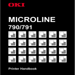
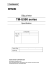
1.3Environmental specification
◆Temperature:
Operation: 0 - 55℃
Storage: -25 - 70℃ (without printing paper)
◆Humidity:
Operation: 10 - 80% RH (no coagulation)
(80% needs 34℃)
Storage: 19 – 90% RH (without printing paper)
7
Figure 1.4 The operation temperature and humidity range
1.4Operation specification
◆Supply voltage: DC +24.0 V ± 2.4 V
◆Current consumption(24V):
M-T530/T540(for 80 ㎜/82.5 ㎜ {3.15inch/3.25inch} paper width type)
High mode:
Average: about 9 A
Peak value: about 14 A
Two parts printing mode:
Average: about 7 A
Peak value: about 11.5 A
Four parts printing mode:
Average: about 4.5 A
Peak value: about 5.5 A
Waiting:
Average: about 0.1 A
M-T510/T520 (for 58/60 ㎜ {2.28inch/2.36inch} paper width type)
High speed mode:
Average: about 6.5 A
Peak value: about 10 A
Two parts printing mode:
Average: about 5 A
Peak value: about 8 A
Four parts printing mode:
Average: about 3.5 A
Peak value: about 5 A
Waiting:
Average: about 0.1 A
8
1.5Security
◆ Can’t impose the over max absolute fixed current and voltage on any
pins
Or, it will bring heat damage.
Max absolute fixed value
Item
Notation
Fixed Value
Unit
Input Voltage
VIN
24.0
V
Storage
Temperature
Tstg
-25 to 70
℃
Storage
Humidity
Hstg
0 to 90
%
◆Operates the printer in the following circumstances:
Recommendatory operation environment
Item
Notation
Standard Value
Unit
Min
Typical
Max
The voltage
supplied by
printer
Vp
21.6
24.0
26.4
V
Operation
temperature
Topr
0
-
55
℃
Operation
humidity(no
coagulation)
Hopr
10
-
80
%
◆Can’t take the power supply to short-circuit for any outputted pins
Takes a low impendence to short-circuit an output pin, maybe it will
bring heat damage because of surpassing circuit.
◆ There are no electric material(as paper etc.) which followed on the
circuit board.
Maybe it will bring heat damage to the pins on the short circuit board
because of the surpassing circuit.
◆Be sure to use the defined cable linker device.
Maybe it will bring fire or strike fire because of the incorrect
linker.
◆This product can’t be disassembled or modified.
The incorrect modification for this product will bring damage, fire or
electric shock.
◆Can’t be used on the high humidity and excessive dust environment.
Maybe it will bring damage, fire or strike fire because of high
humidity and excessive dust.
◆This product can’t be disassembled or modified.
The incorrect modification for this product will bring damage, fire or
9
electric shock.
Chapter II CONFIGURATION AND INSTALLATION
2.1General Configuration
2.1.1The figure of control board configuration
2.1.2Dimension
Height
Width
Depth
About 25 ㎜ {0.98 inch}
About 120 ㎜ {4.72 inch}
About 96 ㎜ {3.78 inch}
10
2.1.3Weight
Mass
About 122g
2.2 PCB installing method
In order to install the control board on the case, the designable case must be conformed to the
following requirements.
● Between the above of electrolytic condenser which on the control board and case, be sure
there are 3 ㎜ or more space.
● Be sure the installation pins of control board have 5 ㎜ or more space.
● Fixes the control board on the mental case.
11
Chapter III SYSTEM INSTALLATION AND OPERATION
3.1 System connection
3.1.1 Power connection
The power connection socket be used to connect printer with exterior
power.
3.1.1.1 Power requirement
24 VDC +/- 10%
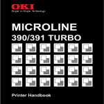
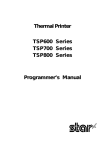
3.1.1.2 Power socket
There are installed power connection socket CN3 on the board, as the
figure 3.1.1.2.
Figure 3.1.1.2 24VDC power connection socket
3.1.1.3 Socket model
5195-04(MOLEX) plug model: 5194(MOLEX)
3.1.1.4 Pin definition
Pin Number
Signal Name
1
GND
2
+24 V DC
12
3
+24 V DC
4
GND
Form 3.1.1 Power socket pin definition
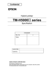
3.1.2 Interface connection
Parallel interface socket
Serial interface socket
Socket Panel Appearance
Illustration:
. For unused interface socket, closes the socket cover.
. If the control board installed on the mental case, needs to fix the two
ends
of serial interface on the case firmly.
3.1.3 Print head connection
3.1.3.1 Print head connection socket
Print head connection socket
13
3.1.3.2 FFC
The FFC cable which connected with the print head, needs to satisfy the
measure requirements as the following figure.
FFC Type(user)
Switch spacing
Switch width
Min connection length
Switch thickness
1.25±0.1 ㎜
0.8±0.05 ㎜
3.5 ㎜
0.25-0.4 ㎜
3.1.4 Operation board connection
The control board could connect single buttons and indicators through this
connection socket.
14
[TK500 Side]
The type of end-user connection:
[User Side]
Plug:
HER-06(JST)
Plug end: SHE-001T-P0.6(JST)
3.1.5 Paper near-end sensor connection
If the user needs to install paper near-end sensor, the connection needs
to according to the following figure. The paper near-end sensor which uses
the mechanical touch switch.
[TK500 Side]
The end-user linker type:
[User Side]
Plug: IL-S-2S-S.C2-S(JAE)
Plug end: IL-S-C2-S-1000(JAE)
3.2 Interface Connection
3.2.1 RS-232 serial interface
3.2.1.1 Specification
Data transmission:
Serial
Synchronization manner: Asynchronous
15
Handshaking signal:
Signal level:
CTS/RTS, DTR/DSR or XON/XOFF control
MARK=-3 to -15V:
Logic “1”/OFF
SPACE=+3 to +15V:
Logic “0”/ON
Baud rate:
4800, 9600, 19200, 38400bps (bps: transmits bit count per second)
Date word length:
8 bit fixed
Check-out manner:
No, Even, Odd
Stop bits:
1 bit or more than 1 bit
Socket(side of the printer): D-SUB9 male thread(positive)
Notes:
.Handshaking signal, baud rate and check-out manner decided by DIP switch
setting. (refer to section 3.3.2)
.The stop bits on the side of the printer fixed 1.
3.2.1.2 Switching between online and offline
The printer goes offline:
1) Between when the power is turned on (or the printer reset) and during
the printer have ready to receive the data.
2) During the self-test.
3) When the cover is open.
4) During paper feeding by taking the paper FEED button.
5) When the printer stops printing due to the paper-end.
6) On the macro execution ready conditions.
7) When an error has occurred.
3.2.1.3 Interface socket pin assignments and signal functions
Interface socket pin assignments and signal functions are described in the
following table:
Signal assignments and functions
Pin
number
Signal
name
Signal
direction
Function
2
RXD
Input
Receive data
3
TXD
Output
Transmit data
4
DTR
Output
1) When DTR/DSR control is selected, this
signal indicates whether the printer is
busy. SPACE indicates that the printer
have ready to receive data, and MARK
indicates that the printer is busy. The
busy condition can be changed by taking
the Memory Switch.(Refer to section
3.3.2.3)
Printer status
Memory Switch
1-3 status
16
O
ff
li
ne
On
Off
1. During the power
turned
on(including
resetting)
to
when the printer
have
ready
to
receive the data.
BUSY
BUSY
2. During the selftest.
BUSY
BUSY
3. When the cover is
open.
---
BUSY
4.
During
paper
feeding taking the
paper FEED button.
---
BUSY
5. When the printer
stops printing due
to a paper-end.
---
BUSY
macro
ready
---
BUSY
7. When an error has
occurred.
---
BUSY
8. When the receive
buffer
becomes
full.(*1)
BUSY
BUSY
6.
On the
execution
conditions.
2) When XON/XOFF control is selected:
The signal indicates whether the printer is
correctly connected and have ready to
receive the data. SPACE indicates that the
printer have ready to receive data. The
signal is always SPACE except in the
following cases:
·During the period from the power turned
on to the printer has ready to receive
data.
·During the self-test.
5
SG
------
Signal ground
Signal assignments and functions (continued)
Pin
number
Signal
name
Signal
direction
Function
6
DSR
Input
This signal indicates whether the host compu
17
ter can receive the data.
SPACE indicates that the host can receive
data, and MARK indicates that the host
can’t receive the data.
When DTR/DSR control is selected, the
printer transmits data after confirming this
signal.
When XON/XOFF control is selected, the
printer does not check this signal.(except
the command transmitted by DLE EOT and GS a)
When XON/XOFF control is selected, the
printer does not check this signal.
Changing DIP switch enables this signal to
be used as a reset signal for the printer.
7
RTS
Output
Same as DTR signal
8
CTS
Input
This signal indicates whether the host can
receive the data.
SPACE indicates that the host computer can
receive the data, and MARK indicates that
the host can’t receive the data.
When DTR/DSR control is selected, the
printer transmits data after confirming this
signal.
When XON/XOFF control is selected, the
printer does not check this signal.(except
the command transmitted by DLE EOT and GS a).
When XON/XOFF control is selected, the
printer does not check this signal.
*1: When the spare space in the receive buffer declined to 100 bytes, the
printer status turns to “buffer full” and keeps “buffer full” status
until the free space in buffer area increased to 140 bytes.
3.2.1.4 XON/XOFF transmission timing
When XON/XOFF control is selected, the printer transmits XON or XOFF signals
as follows. Transmission timing differs depending on the memory switch setting.
XON/XOFF Transmission Timing
Printer status
XON
Transmission
① When the printer goes online
after turning the power on
② When the receive buffer is rele
Memory Switch
ON
OFF
Transmit
Transmit
Transmit
Transmit
18
ased from the buffer full state
③ When the printer switches from
offline to online
④ When the printer recovers from
an error taking the DLE ENQ 1
or DLE ENQ 2 commands
XOFF
Transmission
Notes:
⑤ When the receive buffer becomes
full
⑥ When the printer switches from
online to offline
-----
Transmit
Transmit
Transmit
---
Transmit
Transmit
· The XON code is <11>H and the XOFF code is <13>H.
· In case ③, XON is not transmitted when the receive buffer is full.
· In case ⑥, XOFF is not transmitted when the receive buffer is full.
3.2.1.5 The example of serial interface socket
Could take the cable which have the following signal connections.
The sides of board(MB500)
The sides of user
D-sub9
Socket pin
number
Signal
name
Signal
name
D-SUB9
Plug pin number
1
(NC)
DCD
1
2
RXD
RXD
2
3
TXD
TXD
3
4
DTR
DTR
4
5
SG
SG
5
6
DSR
DSR
6
7
RTS
RTS
7
8
CTS
CTS
8
9
(NC)
RI
9
Couldn’t take the cable which have the following signal connections.
The sides of board(MB-500)
D-sub9
Socket pin
number
Signal name
The sides of user
Signal
name
D-SUB9
Plug pin number
19
1
(NC)
DCD
1
2
RXD
RXD
2
3
TXD
TXD
3
4
DTR
DTR
4
5
SG
SG
5
6
DSR
DSR
6
7
RTS
RTS
7
8
CTS
CTS
8
9
(NC)
RI
9
Note:
After turning the printer power on and initializing,
transmitting data to printer.
3.2.1.6 Notes on setting the memory switch 1-3
1) The printer only stops operating but not in busy conditions, when an
error has occurred, the cover opened, without paper, or paper fed .
2) When setting the memory switch “ON”, and enabling the handshaking
effectively, be sure to check the printer status taking “GS a” command
and ASB function. In such circumstances, the default value of n for “GS
a” is 2. The printer automatically transmits the printer status, it
decides by the change of online/offline status.
3) When taking DLE EOT, be sure that the receive buffer is empty.
· The host can’t transmit the data when the printer is in busy
conditions:
When the printer is busy because of the buffer area is full, If occurs
errors, DLE EOT can’t be used.
· The host can transmit the data when the printer is in busy conditions:
If the buffer area is full when transmitting the bit image, it is the
same as the DLE EOT which transmitted when dealing with bit image,
both are bit image data. When the receive buffer area is full, the
transmitted date could loss.
For example: When taking 4KB receive buffer, every time transmits a
line data, checks the printer conditions by “GS r 1”. Transmits one
line data to make sure the receive buffer won’t be filled.
3.2.1.7 Resetting the printer by the serial interface
Through changing the set of DIP switch, the printer could repost by
interface pin 6.
Reset Changed
Signal line
DIP switch
Reset condition
Pin 6(DSR)
DSW 2-8: ON
MARK level inputting
If needs to reset, the printer must be satisfied the following
20
requirements.
. DC characters:
Reposition DC Characters
Pin 6(DSR)
Positive reposition
voltage
VA
-15 to -3V
Negative reposition
voltage
AN
+3 to +15V
Positive reposition
voltage
IA
-5.3 mA (max)
Negative reposition
voltage
IN
-5.0 mA (max)
Input impedance
RIN
3KΩ(min)
.AC Characters:
The min reset plus width: TRS 1 millisecond (min)
.When taking pin 6(DSR) (DIP switch 2-8 is ON):
The min reposition plus width (pin 6)
When pin 6(DSR) and DIP switch 2-8 are ON, the printer resets.
Note: When the signal inputted which is not satisfied with the above
requirements, the printer operation can’t be confirmed.
3.2.2 IEEE 1284 Bidirectional Parallel Interface
Copyright (C) 1994 by the Institute of Electrical and Electronic Engineers,
Inc.
3.2.2.1 Compatible Mode
(The data sent to the printer by the host: Censorings Compatibility)
(1) Introduction
Compatible mode supports Censorings parallel interface compatibility.
(2) Specifications
Data transmission:
8-bit parallel
21
Synchronization:
Handshaking:
Signal levels:
Connector:
External supply nStrobe signal
nAck and Busy signal
TTL compatibility
ADS-B36BLFDR176(Honda) or equivalent
products(IEEE 1284 Type B)
(3) Switching between online and offline
The printer is not equipped with any online/offline switch. The printer
enters into offline status in the following conditions:
1) When the power turned on or initialized the printer by reposition
signal(nlnit) from the interface to the head that the printer has
ready to receive data.
2) During self-test.
3) When the cover is open.
4) During paper feeding by the paper FEED button.
5) When the printer stops printing due to paper-end(in cases when
without paper is detected by either the paper-end sensor or the
paper near-end sensor and stops printing which sets by “ESC c 4”).
6) On the macro execution conditions.
7) When an error has occurred.
3.2.2.2 Sending back data mode
Transmits the status data from the printer to the host by four bits
mode(nibble) or byte mode.
Note: At present only supports sending back data by nibble mode.
. Description
This mode allowed data transmission from the asynchronous printer under the
host control.
Transmits data by four bits mode which works through the existed control
line of four bits each group(a Nibble). In the eight bits mode, transmits
data which completed by dealing with the eight data line as the bidirectional.
Both modes can’t work at the same time as the compatible mode, Or, it will
cause half-duplex transmission.
3.2.2.3 The interface pin assignments under the each mode
Pin
Source
Compatibility Mode
Four Bits Mode
1
2
3
4
5
6
7
8
9
Host
Host/Ptr
Host/Ptr
Host/Ptr
Host/Ptr
Host/Ptr
Host/Ptr
Host/Ptr
Host/Ptr
nStrobe
Data0(LSB)
Data1
Data2
Data3
Data4
Data5
Data6r
Data7(MSB)
HostCIk
Data0(LSB)
Data1
Data2
Data3
Data4
Data5
Data6
Data7(MSB)
22
10
11
12
13
14
15
16
17
18
19
20
21
22
23
24
25
26
27
28
29
30
31
32
33
34
35
36
Printer
Printer
Printer
Printer
Host
Printer
Host
Printer
Printer
Printer
Host
nAck
Busy
Perror
Select
nAutoFd
NC
GND
FG
Logic-H
GND
GND
GND
GND
GND
GND
GND
GND
GND
GND
GND
GND
nlnit
nFault
GND
DK-STATUS
+5V
nSelectln
PtrCIk
PtrBusy/Data3,7
AckDataReq/Data2,6
Xflag/Data1,5
HostBusy
ND
GND
FG
Logic-H
GND
GND
GND
GND
GND
GND
GND
GND
GND
GND
GND
GND
nlnit
nDataAvail/Data0,4
ND
ND
ND
1284-Active
*NC: Not Connected
ND: Not Defined
Notes: 1.The letter “n” before signal names indicates that the low level is
effective.
2. If the host can’t provide all signal lines which lists as above,
all communication modes will be failed.
3. For interface, signal lines needed to use the twisted pair cable,
and the return sides connected to the signal ground.
4. Interface status setting are taking TTL level which is satisfy the
following characters. In addition, both rise time and fall time of
all signals should be no more than 0.5 microsecond.
5. Data transmission shouldn’t ignore the nAck or Busy signal.
Transmits data when ignoring nAck or Busy signal, it will cause the
data losing. (For printer, transmits data should at the behind of
checking nAck signal or when the Busy signal in low level.)
6. Interface cables should be the min length which is required.
23
3.2.2.4 Electrical Characters
DC Character (Except for Logic –H+5V)
Characteristics
Symbol
Specifications
Conditions
Min
Max
Output
voltage
Output
voltage
Output
current
Output
current
HIGH
VOH
*2.4V
5.5V
*LoH=0.32mA
LOW
VOL
-0.5V
*0.4V
LOL=12 mA
HIGH
LOH
0.32mA
-
VOH=2.4V
LOW
LOL
-12mA
-
VOL=0.4V
Input
voltage
Input
voltage
Input
voltage
Input
voltage
HIGH
VIH
2.0V
-
LOW
VIL
-
0.8V
HIGH
VIH
-
-0.32mA
VIH=2.0V
LOW
VIL
-
12mA
VIL=0.8V
Logic-H Signal Sender Characters
Characteristics Symbol
Output
voltage
Output
voltage
Specifications
Min
Max
HIGH
VOH
3.0V
5.5V
LOW
VOL
-
2.0V
Conditions
While the power
is OFF
+5V Signal Sender Characters
Characteristics Symbol
Specifications
Min
Output
voltage
Output
voltage
Output
current
Output
current
Conditions
Max
HIGH
VOH
*2.4V
5.5V
LOW
VOL
-
-**
HIGH
LOH
-
0.32mA
-
LOW
LOL
-**
* LOH =0.32mA
While the power
is OFF
VOH=2.4V
While the power
is OFF
24
**No guarantee offered to VOL and LOL while the power is turned off.
3.2.2.5 Parallel data receiving timing
Parallel interface signal timing graphic as follows (compatible mode)
3.2.2.6 Repositing printer by the parallel interface
At the compatible mode, the printer resets by the interface nlnit
signal(pin31), The nlnit signal brought by changing DIP switch setting. To
enable the printer reset, should be satisfied the following signal timing.
.DC characters
TTL level
.AC characters
The min reset plus width: TRS 50 microsecond (min)
Note: The character “n” before the signal name indicates that the low
is effective.
3.2.2.7 Receiving printer status through the bidirectional parallel interface
In the bidirectional parallel interface specifications, the printer
status transmission is available by the bidirectional communication
25
facility which operates in the 4 bits/8 bits modes accordance with the IEEE
1284 standard.
In such circumstances, as opposed to the RS-232 serial interface
specification, the real-time interruptions from the printer to the host are
disabled, and thus, precautions must be taken as the following.
1) Allowable capacity of the printer internal buffer is 99 bytes (except ASB
status). Status signals exceeding this capacity will be discarded. To
prevent possible loss of status, the host shall be ready for data
acceptance (Reverse Mode).
2) When ASB is used, the host is preferably in the wait state for data
acceptance(Reverse Idle Mode). When this state is not available, the host
shall enter the Reverse Mode to constantly monitor the presence of data.
3) When ASB is used, preference shall be given to the ASB state for
transmission over the other states signals. Any accumulated ASB statee
signals left for transmission from the last to the newest ASB status
transmission shall be transmitted together at one time as one ASB state
showing the presence of change, followed by the latest ASB state.
Example: In the normal (wait) state, the ASB status is configured as follows.
First Status
Second Status
Third Status
Fourth Status
0000 0000
0000 0000
0000 0000
0000 0000
When the following sequence of operations proceeds and near end is detected,
and the FEED button is pressed and released, the following pieces of data
are accumulated.
First Status
Second Status
Third status
Fourth Status
0001 0000
0000 0000
0000 0011
0000 0000
① Near end detection
0101 0000
0000 0000
0000 0011
0000 0000
0000 0011
0000 0000
② The printer board is opened
0001 0000
0000 0000
③ The printer board is closed
When the ASB status is received following this, a total of eight (8)
bytes of ASB will be transmitted as follows.
Accumulated ASB(①+②+③)
First Status
Second Status Third Status
Fourth Status
0101 1000
0000 0000
Accumulated ASB(①+②+③)
The latest ASB(④)
First Status
Second Status
0001 0000
0000 0000
0000 0011
0000 0000
Third Status
Fourth Status
0000 0011
0000 0000
Fourth Status
26
3.3 Panel Buttons and Indicators
3.3.1 Panel buttons
1) Feed button
Type: Non-locking push button
Function:
When BM sensor disabled, the printer feeds paper one line(based on the
line spacing which set by ESC 2 and ESC 3). When BM enabled, the length
which feeds by printer is the BM paper length unit.
Push feed paper button will not feed paper at the following states:
① Disabled the buttons when takes ESC 5 command.
② Paper-end sensor tests no paper.
③ Raises the print head bar.
·On the conditions of macro waiting execution, push feed paper and execute
the defined macro.
· At the process of self-test, push keys could stop self-test printing,
push again could self-test continued.
Note: ESC c 5 command could turn buttons function on/off. When push
buttons disabled, it is no effective when push the buttons.
3.3.2 Indicators
1) Power supply LED: Green
On: Power supply is stable.
Off: Power supply is not stable.
2) Roll paper end LED: Red
On: The roll paper near end or real end.
Off: Paper is loaded(normal condition).
Flashing: ·Self-test waiting state(refer to 3.4) or macro waiting
state.
· Execute macro waiting state(when use “executing
macro” command)
Table 3.3 waiting state indication
State
Waiting for selftest printing to be
continued or have
ready to execute
macro.
Paper
pattern
LED
flashing
about 320ms
Recovery conditions
Pressing
the
feed
button caused self-test
printing
to
be
continued or executed
macro.
Note: A macro could be executed r times(r means the times that the macro
27
be executed) as an definition. Macro could be executed continually,
and could push the paper feed button once. If execute the macro
pattern through pushing the button, the paper end indicator will flash
and indicates that have ready to execute macro.(Refer to Section 4:
command)
3) Error LED:
Red
On:
Offline (except during paper feeding using the feed button
and during the self-test)
Off: Normal operation
Flashing: Error state(Refer to 3.6)
Power Supply
Paper-end
Error
Paper carrier button
Figure 3.3.2 Panel buttons and indicators
3.4 Special operation mode
3.4.1 Self-test
Self-test could test whether the printer is normal operation. If can print
self-test list correctly, it indicates that the printer is normal except the
connection with host, Or needs to test.
1) The printer has a self-test function that checks the following:
·Control circuit functions
·The printer structure state when connecting to control board
·Print quality
·Interface type and operation conditions
·Control software version
·DIP switch settings
·Memory switch settings
2) Executing the self-test
Hold down the feed button and turn the printer on with the cover closed,
then the current printer state (*1) is printed.
(*1) · Control software version
· Interface type and communication state
· DIP switch settings
28
· Memory switch settings
3) Self-test standby state
After printing the current printer state, the printer prints the message
“Self-test printing, please press feeding button.” The paper out LED
indicator flashes and the printer enters the test printing (*2) standby
state. Press the feed button to start test printing.
(*2) · Prints a roll paper mode that only takes the internal character
set.
4) Ending the self-test
After a number of lines are printed, the printer indicates the end of
the self-test by print”*** completed***,”, and initializes and enters
into the standard mode.(Refer to section 3.9)
3.4.2 Hex Dump
1) Hexadecimal dumping function
This function prints the data transmitted from the host in
hexadecimal numbers and in their corresponding characters.
2) Starting hexadecimal dumping
Starting hexadecimal dumping has two patterns:
--Turns the power on while pressing the paper feed button
--Executes the GS ( A.
The printer first prints “Hexadecimal Dump”, and then prints the
received print data in hexadecimal numbers and in their corresponding
characters.
Notes:
1. If a character does not correspond to the data received, the
printer prints “.”.
2. During hexadecimal dumping, any commands other than DLE EOT,
DLE ENQ, and DLE DC4 do not function.
3. Insufficient print data to fill the last line can be printed
by mode of the printer is offline(for example press the paper
feed button).
3) Ending hexadecimal dumping
Hexadecimal dumping ends by turning the power off, pressing the paper
feed button three times, or resetting the printer after printing has
finished.
<Printing example>
29
3.5 DIP switch and memory switch settings
3.5.1 DIP switch setting
3.5.1.1 DIP switch
There are two DIP switches on the control board, and the number of DIP
switch prints on it, signs SW1 and SW2, the graphics as follows:
Note: The change of DIP switch setting only affects when the printer
turned the power on again or reset.
3.5.1.2 DIP switch 1
DIP switch 1(SW1)
Switch
No.
Function
ON
OFF
Default
1
Black mark
sensor
Enabled
Disabled
Off
2
Selects
communication
interface
Refer to table 3.5.2
4
RS232 serial
interface
handshaking
XON/XOFF
DTR/DSR or
RTS/CTS
Off(*)
5
Serial interface
parity checkout
Used
Unused
Off(*)
6
Serial interface
Even checko
Odd checko
Off(*)
3
Off
Off
30
checkout mode
7
ut
Selects serial
interface baud
rate
8
ut
Refer to table3.5.3
Off(*)
Off(*)
(*) only affects when selecting RS232 serial interface.
Communication-ports selecting
Port
DIP switch number
2
3
Parallel interface(IEEE1284
bidirectional parallel interface)
Off
Off
Serial interface(RS232)
Off
On
Baud rate selecting
Transmission speed(baud rateBPS)
DIP switch number
7
8
4800
On
On
9600
Off
On
19200
On
Off
38400
Off
Off
Note: BPS-bits per second
3.5.1.3 DIP switch 2
DIP switch 2(SW2)
Switch
number
Function
1
Print head model
selecting
2
3
ON
OFF
Default
Off
Off
Printing chroma
selecting
Refer to 3.5.6
5
Operation mode
selecting
Refer to 3.5.7
6
Manufacture using
Off(*1)
7
Serial interface DSR
signal SPACE level
reset, Logic 0
Off
4
8
Serial interface DSR
signal MARK level
reset, Logic 1
Off
Off
--
Off
-Off(*2)
Enabled
Disabled
*1: OFF is fixed
*2: only affects when selected RS232 serial interface.
Note: At present the set of bit8 is no effective.
31
Table 3.5.6 Printing chroma selecting
Chroma grade
Printing chroma
Switch number
3
4
1
Tiny
On
On
2
Normal
Off
Off
3
Thick
On
Off
4
Dense
Off
On
Table 3.5.7 Operation mode selecting
Operation mode
Switch number
5
Hex printing(*)
On
Normal
Off
Note: This operation mode prints the any one of receiving data by hex
value.
3.5.2 Set memory function switch
Except for DIP SW1 and SW2, Could use memory function setting switch to
take the other function settings, these settings confirmed by the specific
printing setting commands, the setting parameters will be stored in the printer
non-easy losing memory, and it will not lose when turning the power off.
The memory function switch 1
Switch
number
Function
ON(1)
OFF(0)
Default
Note
1
Reserved
---
0 is fixed
0
2
Reserved
---
O is fixed
0
3
BUSY
conditions
The receiving
buffer is full
The
receiving
buffer is
full or
offline
0
4
Receiving
error dealt
with
Ignored
Prints “?”
0
*1
5
Change a new
line
automatically
Enabled
Disabled
0
*2
6
Reserved
---
0 is fixed
0
7
Reserved
---
0 is fixed
0
32
8
Reserved
---
0 is fixed
0
Notes: *1 only affects under the serial interface.
*2 only affects under the parallel interface. Please refer to the
illustration of CR command.
Memory function switches 2,3,4,5,6,7
Switch
number
Function
ON(1)
OFF(0)
Default
1
Reserved
---
0 is fixed
0
2
Reserved
---
0 is fixed
0
3
Reserved
---
0 is fixed
0
4
Reserved
---
0 is fixed
0
5
Reserved
---
0 is fixed
0
6
Reserved
---
0 is fixed
0
7
Reserved
---
0 is fixed
0
8
Reserved
---
0 is fixed
0
Note
Memory function switch 8
Switch
number
Function
1
Printing mode
control
2
ON(1)
OFF(0)
Default
0
0
3
Retreats
paper
Enabled
Disabled
0
4
Installs
cutter-paper
automatically
Not installed
Installed
0
5
Reserved
---
0 is fixed
0
6
The step of
retreating
paper
88 steps
108 steps
0
7
Reserved
---
O is fixed
0
Initialized
0
8
Note
When up-elect, Not
initialized
initialized
black
mark
position
*1
*1: Takes this function when only retreating printing institution be used.
If takes the retreating function, the printer will take the following
operation:
. After taking GS V command to cut paper, will execute retreating
operation(when the black mark disabled).
. Set the printing starting position at the opposite direction of cutting
paper
position by GS ( F command.
Note: At present not supports the selecting function of Memory switch 8’s
33
bit 0, bit 1.
3.6 Error Processing
3.6.1 Error type
1) Error that recovers automatically
Automatically Recoverable Error
Error
Description
Print head over
temperature
error
The
temperature
of
the
print head
is over 57
℃
LED flashing pattern
Recovery
Recovers
automatically
when the print
head
cools
below 45℃.
2) Error can be recovered
Error can be recovered
Error
Description
LED flashing pattern
Recovery
The cover
open error
The printer
can’t work
because of
the print
head opened.
When
installing
cover on the
print head,
then restoring
by DLR ENQ 1
or DLE ENQ 2
Auto-cutter
error
Abnormality
in the autocutter.
If occur paper
jams, recovers
by DLE ENQ 1
or DLE ENQ 2
when the
jammed paper
be exclusion.
BM sensor
test error
Can’t test
BM even the
roll paper
BM printing
correct
Installed the
correct BM
paper again,
then restoring
by DLE ENQ 1
or DLE ENQ 2
3) Error can’t be recovered
Error can’t be recovered
Error
Description
CPU executin
CPU execute
LED flashing pattern
Recovery
Can’t recover
34
g error
s one error
address or
not
connects
I/F board
y
Memory or
dot list
read error
Tests an
error when
executing
read
checkout
Can’t
recovery
High voltage
error
The voltage
provides
too low
Can’t
recovery
Low voltage
error
The printer
not linkers
well or
inner
linker
error
Can’t
recovery
CPU linker
error
Can’t
recovery
Note: When occurring any one of the above error, please turns the power
off as soon as possible.
3.6.2 Operation when an error is detected
The printer executes the following operations when detecting an error:
. Stops all mechanical operations.
. Enter into “BUSY” state(DIP switch, when the memory switch 1-3 is
off).
. Flashes the error LED.
3.6.3 Data reception error
If any of the following data reception errors occur during serial interface
communication, the printer prints “?” or ignores the data, according to
the setting of Memory Switch 1.
.Checkout error
.Framing error
.Overrun error
35
3.7 Status test
3.7.1 Paper status test
The printer has the following two paper sensors:
1) Roll paper end sensor
This sensor tests whether there are paper in print head. When the printer
detects the paper end, stops printing.
2) Roll paper near-end sensor
This sensor tests whether the paper is near-end.
When the roll paper narrowed to some extent, the roll paper-end detector
tests “paper near-end” signal, paper-end detector (“no paper” light)
turns on. If this sensor to be used (use ESC c 4 command), when printer
test paper near-end signal, stop printing.
Notes: ·Installed the new roll paper and covered the bar, the printer will
print again.
·The paper near-end sensor set by user.
3.7.2 Print head bar status test
Print head bar sensor tests the open/close state of print head bar, there
are installing rubber stick which takes to feed paper on the bar. On the
waiting conditions, when the bar sensor tests that the bar has raised, the
printer enters into offline conditions, the printer recovered automatically
after closing the bar.
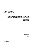
3.8 Notes on the BM function
It could take the printing paper which prints BM and to realize the
accurate orientation printing function.
The BM function which needs to move the DIP SW1-1 to ON, then resets the
printer, Refer to section 3.5.1.2.
The following graphic shows the relative connection of black mark testing
position, cutting paper position and printing starting position. (The
distance which from the BM testing sensor of M-T530/T540 printing framework
to print head is about 17.6 ㎜, to cutter blade 33.6 ㎜, these framework are
fixed.)
The connection of them could be understand like this: when carries paper to
the BM which under the BM sensor(meanwhile the printer detects BM), the
cutter is front of the BM which about 33.6 ㎜, At this moment, the print head
is front of the BM which about 17.6 ㎜, as the following graphic.
As the graphic, when the BM testing sensor tests the BM, the BM paper
36
passes the testing sensor about 2 ㎜. In order to repeat testing error, the
printer doesn’t test the BM at the following about 2 ㎝.
The default printing starting position and cutting paper position are the
opposite position as the following graphic, the user could adjust by GS ( F
command.
3.9 Page Mode
3.9.1 Introduction
The printer has two operation modes (only on the conditions of
selecting roll paper as the paper source): normal mode and page mode. Under
the normal mode, each time the printer receives the data or begins to print
and feeds paper after feeding paper command. Under the page mode, all the
printing data and feeding paper commands received by printer will be dealt
with and stored in a special memory, the printer does not to do any
operation. When received ESC FF or FF commands, all the stored data will be
printed.
For example: When received data “ABCDEF”<LF> under the normal mode, the
printer prints the characters “ABCDEF” and feeds the paper by one line.
Under the page mode, “ABCDEF” be wrote to a special printing data area in
the memory, at the same time the printing position descend one line of the
next printing data in data area. ESC L command makes the printer to the
page mode, all the following data and commands dealt with according to the
page mode. Executed ESC FF command which could print all the received data,
but executes FF command which may lead the printer to return to the normal
mode after printing all the data. Executes ESC S command which will lead
37
the printer to return to the normal mode directly but not to print the
received data under the page mode , these data will be deleted from the
memory.
Figure 3.9.1 Transform between normal mode and page mode
3.9.2 The setting value under the normal mode and page mode
1) The commands and parameters are the same under the normal mode and page
mode. But ESC SP, ESC 2, ESC 3 commands have the different setting
values under the normal mode and page mode , It will be recorded
respectively under the different mode.
2) Under the normal mode, If takes the roll paper which the width is 82.5
㎜ , the max printing width of printing dot image is 640 dots; But the
same roll paper under the page mode could be print 664 dots at the
direction of y(paper feeding direction). (The above needed to take the
following setting: the y direction printable area is 664 dots set by ESC
W command, the value of the printing direction parameters n set by ESC T
is 1 or 3.)
38
Chapter IV Printing Control Commands
4.1Command Table
Name
Command
Command
Type
Standard
Mode
Execute
command
Set
Command
Page
Mode
HT
Horizontal tab
○
○
○
LF
Print and line feed
○
○
○
FF
Print and turn to
standard mode(under the
page mode)
○
Ignored
○
CR
Print and carriage
return
○
○
○
CAN
Cancel printing data
under the page mode
○
Ignored
○
DLE EOT
Real-time status
transmission
○
○
○
DLE ENQ
Real-time request to
printer
○
○
○
ESC FF
Print data under the
page mode
○
Ignored
○
ESC SP
Set right-side character
spacing
○
○
ESC $
Set absolute printing
position
○
○
ESC %
Select/cancel userdefined character set
○
○
○
ESC &
Define user-defined
characters
○
○
○
ESC *
Select bit-image mode
○
○
ESC -
Turn underline mode
on/off
○
○
○
ESC 2
Select default line
spacing
○
○
○
○
○
○
39
ESC 3
Set line spacing
○
○
○
ESC ?
Cancel user-defined
character
○
○
○
ESC @
Initialize printer
○
○
○
ESC D
Set horizontal tab
positions
○
○
○
ESC E
Turn emphasized mode
on/off
○
○
○
ESC G
Turn double-strike mode
on/off
○
○
○
ESC i
Full cut
○
○
○
ESC J
Feed paper and printing
○
○
○
ESC L
Select page mode
○
(○)
Ignored
ESC m
Half cut
○
○
○
ESC M
Select character type
○
○
ESC R
Select an international
character set
○
○
ESC S
Select standard mode
Ignored
○
ESC T
Select printing
direction under the page
mode
○
▲
○
ESC V
Turn clockwise 90°
revolved on/off
○
○
▲
ESC W
Set printable area under
the page mode
○
▲
○
ESC ﹨
Set relative printing
position
○
○
ESC a
Select justification
○
(○)
○
ESC c 3
Select paper sensor to
output paper-end signal
○
○
○
ESC c 4
Select paper sensor(s)
to stop printing
○
○
○
ESC c 5
Enable/disable panel
buttons
○
○
○
ESC d
Printing and feeding n
lines
○
○
ESC t
Select character code
table
○
○
○
ESC {
Turn upside-down
printing mode on/off
○
(○)
○
FS p
Print NV bit image
○
○
FS q
Define NV bit image
(○)
○
○
○
○
○
○
○
○
40
GS FF
Carries the BM printing
paper to the printing
starting position
○
○
○
GS !
Set character size
○
○
GS $
Set absolute vertical
printing position under
the page mode
Ignored
○
GS *
Define download bit
image
○
○
GS ( A
Execute test print
○
○
Ignored
GS ( E
User setting command
○
○
(○)
Disabled
GS ( F
Set adjustable value
○
○
○
GS ( K
Select printing control
mode
○
○
○
GS ( M
User-defined printer
control value
○
(○)
▲
GS /
Print download bit image
○
●
○
GS :
Begin/finish macro
definition
○
○
○
○
GS B
Turn opposite blank
printing mode on/off
○
○
○
GS C 0
Set count value printing
mode
○
○
○
GS C 1
Select count mode(A)
○
○
○
GS C 2
Set count value
○
○
○
GS C ;
Select count mode(B)
○
○
○
GS H
Select HRI character
printing position
○
○
○
GS I
Transmit printer ID
○
○
GS L
Set left side blank
measure
(○)
○
GS T
Set printing position to
the start printing line
○
○
Ignored
GS V
Select cutting mode and
cut paper
○
(○)
○
GS W
Set printable width
(○)
▲
GS ﹨
Set relative vertical
printing position under
the page mode
○
Ignored
○
GS ^
Operate macro
○
○
○
GS a
Enable/disable automatic
status back(ASB)
○
○
○
○
GS b
Turn level and smooth on
○
○
○
○
○
○
○
○
○
41
/off
GS c
Printing count value
GS f
Select HRI character
type
GS h
Set bar code height
GS k
Print bar code
GS r
○
○
○
○
○
○
○
○
○
○
●
○
Transmit status
○
○
○
GS v 0
Print grating bit image
○
●
○
GS w
Set bar code width
○
○
Chinese commands table
Command
Name
Command Type
Execute
Command
Set
Command
Standard
Mode
Page
Mode
FS !
Set print mode(s) for
Chinese characters
○
○
○
FS &
Set Chinese mode
○
○
○
FS -
Turn underline mode
on/off for Chinese
characters
○
○
○
FS .
Cancel Chinese
character mode
○
○
○
FS 2
Define user-defined
Chinese characters
○
○
○
FS C
Select Chinese
character code system
○
○
○
FS S
Set left-and right-side
Chinese character
spacing
○
○
○
FS W
Turn quadruple size
mode on/off for Chinese
characters
○
○
○
Command type
Execute command: The printer executes this command, and changes the command
no affects the next data.
Set command:
The printer set through relative symbol, these set will
affect the next data.
Standard mode
○: Enabled
(○): This command only affects when the command stand at the beginning
of a line.
●: Only affects when there are no data in the buffer area.
Page mode
42
○: Enable
▲: Only could set data value.
Disabled: Parameter dealt with as the printable data.
Ignored: Ignored all the command codes, exclude parameters, and not
executes any operation.
4.2 Command Introduction
4.2.1 Command notation
〔Name〕
〔Format〕
The name of the command.
The code sequence.
〔 〕k indicates the contents of the〔 〕should be repeated
k times.
〔Range〕
Gives the allowable ranges.
〔Description〕
Describes the function of the command.
〔Specification〕
Specification describe the use of command.
〔Notes〕
Provides important information on setting and using the
printer command, if necessary.
〔Short data〕
If the command with the parameter, gives the parameter
short data.
〔Reference〕
Gives the relevant reference.
The data signed by <>A, is hexadecimal.
The data signed by<>B, is binary system.
4.2.2 Explanation of Terms
(1) Receive buffer
The receive buffer is used to store data from the host. All receive
data is stored in this buffer and processed in the order receiving.
Then solves by sequence.
(2) Print buffer
The print buffer is used to store image data for printing.
(3) Print full-buffer
The status indicates that the print buffer is full. When the print
buffer is full, If appears new print data, the data in the print
buffer area will be printed, and executed the operation of changing a
new line. The operation same as the LF command.
(4) Line starting point
Satisfied the following conditions defined starting point.
·There are no printing data in the print buffer area.
·Not passes the printing position which designated by ESC $ or ESC ﹨
command.
43
(5) The area could be printed
At the specification of printer, it can print the max area. The
printable area about this printer as follows:
Under the standard mode, the length of the horizontal direction:
①
82.5 ㎜ Paper width type:
about 80 ㎜ {640/203.2inch}
79.5 ㎜ Paper width type:
about 72 ㎜ {576/203.2inch}
60 ㎜ Paper width type:
about 56 ㎜{448/203.2inch}
58 ㎜ Paper width type:
about 54 ㎜ {432/203.2inch}
②
Under the page mode, the length of the horizontal direction:
82.5 ㎜ Paper width type:
about 80 ㎜ {640/203.2inch}
79.5 ㎜ Paper width type:
about 72 ㎜ {576/203.2inch}
60 ㎜ Paper width type:
about 56 ㎜ {448/203.2inch}
58 ㎜ Paper width type:
③
about 54 ㎜ {432/203.2inch}
Under the page mode, the length of the vertical direction:
82.5 ㎜ Paper width type:
about 83 ㎜ {664/203.2inch}
79.5 ㎜ Paper width type:
about 92 ㎜ {738/203.2inch}
60 ㎜ Paper width type:
about 119 ㎜ {949/203.2inch}
58 ㎜ Paper width type:
about 123 ㎜ {984/203.2inch}
(6) Printable area
The printable range is set by command , the printable area must be
not more than the area which could be printed.
(7) Ignored
All the command contains parameter on this condition, be read, then
be discarded, but not takes any operation.
(8) Inch
A unit of length. One inch is 25.4 ㎜
(9) MSB
The highest validity
(10)LSB
The lowest validity
(11) Baseline
The standard position of the character data which stored in the
printing
buffer . The normal character position under the standard mode and
page mode as the following graphics:
*
44
When the character selected A, the width is 21 dots.
When the character selected B, the width is 16 dots.
Revolve the character under the standard mode: (only when the character A
selected)
4.3 Command Specification
HT
[Name]
[Format]
Horizontal tab
ASCII
HT
Hex
09
Decimal
9
[Description]
The printing position moved to the next position.
[Specification]
.This command will be ignored, if haven’t set the next
horizontal anchor point position.
.If the next horizontal anchor point out of the
printable area , moves the printing position to
“printing width +1”.
.The horizontal anchor point position sets by ESC D
command.
.This command received when the printing position
located on “printable area width +1”, the printer
executes the full printing buffer area and prints the
current line, and deals with the anchor position at the
beginning of the next line.
[Reference]
ESC D
LF
[Name]
[Format]
[Description]
Print and line feed
ASCII
LF
Hex
0A
Decimal
10
Prints the data in the buffer and feeds one line, based on
45
[Notes]
[Reference]
the current line spacing.
The printing position set at the beginning position of the
line by this order.
ESC2, ESC3
FF
[Name]
① Print and turn to standard mode (under the page mode)
② Print and carry BM paper to the printing starting position
① When selects the page mode:
[Description]
Prints all the data in the printing buffer area and turns to
the normal mode.
[Notes]
.This command only affects under the page mode.
.The data in the printing buffer deleted after printing.
.Resets the printable area which sets by ESC W to default set.
.This command sets the printing position to the line starting
position.
[Reference]
ESC FF, ESC L, ESC S
② When BM sensor affects:
[Description]
Prints the data in the printing buffer area and carries the BM
paper to the printing starting position.
[Notes]
.This command only enables when the BM sensor setting is
effective by DIP SW1-1.
.This command sets that the printing position is the line
starting position.
.If executing this command at the printing starting position
which contains BM printing paper, the printer feeds the BM
printing paper to the next printing starting position.
[Reference]
GS ( F, GS FF, 3.5.1.2, DIP switch 1
CR
[Name]
[Format]
[Description]
[Specification]
Print and carriage return
ASCII CR
Hex
0D
Decimal 13
When automatic line feed is enabled, functions the same as LF.
When automatic line feed is disabled, this command will be
ignored.
.For serial interface mode, the function of feeding paper
will be ignored.
.For parallel interface mode , sets this command through
storage switch 1-5.
.The starting position sets to the printing starting position.
46
[Reference]
LF
CAN
[Name]
[Format]
[Description]
[Specification]
[Reference]
Cancel printing data under the page mode
ASCII
CAN
Hex
18
Decimal 24
Under the page mode, deletes all the printing data in the
current printable area.
.Enable this command only under the page mode.
.The data in the designated printable area to be deleted.
ESC L, ESC W
DLE EOT n
[Name]
[Format]
[Range]
[Description]
[Specification]
Transmit real-time status
ASCII
DLE
EOT
n
Hex
10
04
n
Decimal
16
4
n
1≤n≤4
Takes real-time status. Parameter n is used to designate the
transmission printable area, the definition as follows:
n=1: Transmits printer status.
n=2: Transmits offline cause status.
n=3: Transmits error cause status.
n=4: Transmits roll paper sensor status.
·Transmit the current status, each byte per status.
·Printer couldn’t be sure whether the host can receive data
when transmitting status.
·Printer starts to execute when received this command.
· Under the serial interface pattern, If the printer is
offline, the received buffer is full, or the error
occurred, also can execute this command.
. Under the parallel interface pattern, when the printer is
busy, can’t execute this command. When the printer is
offline, the Memory Switch 1-3 is on , the printer can’t
enter into BUSY condition.
. When return (ASB) through GS a command enabled conditions,
should be distinguished the condition sent by DLE EOT
command with ASB status. (Refer to appendix C, the
identified sending conditions.)
· If the external equipment command not be selected by
printer, the command selected by ESC= also affects.
47
[Notes]
·Whenever received <10>H<04>H<n>(1≤n≤4) data sequence, the
printer performs this command.
For example:
ESC * m nL nH d1...dK, d1=<10>H, d3=<01>H
·Do not embed this command within another command.
For example:
If want to transmit ESC 3 n to printer, before transmitting n,
DTR(for the host is DSR) is MARK, So, before n received, occurs
that DLE EOT 3 interrupted, the code<10>H of DLE EOT 3 will be
dealt with as the code<10> of ESC 3.
n=1 Printer status
Off/On
Hex
Decimal
Function
0
Off
00
0
No used. Off selected
1
On
02
2
No used. On selected
2
On
04
4
No used. On selected
3
Off
00
0
Online
On
08
8
Offline
4
On
10
16
No used. On selected
5
Off
00
0
No used. Off selected
6
Off
00
0
No used. Off selected
7
Off
00
0
No used. Off selected
Bit
Note: bit 5: the online error is the process of the printer executes macro
command period and self-test period which waited push buttons.
n=2: Offline cause status
Bit
Off/On
Hex
Decimal
Function
0
Off
00
0
No used. Off selected
1
On
02
2
No used. On selected
2
Off
00
0
The print head lever is closed
On
04
4
The print head lever is opened
3
Off
00
0
No used. Off selected
4
On
10
16
No used. On selected
5
Off
00
0
No used. Off selected
6
Off
00
0
No used. Off selected
7
Off
00
0
No used. Off selected
Bit 5: When the without paper detector test that the paper have used and
stopped printing, it is on.
n=3: Error cause status
Bit
Off/On
Hex
Decimal
Function
0
Off
00
0
No used. Off selected
1
On
02
2
No used. On selected
2
Off
00
0
No used. Off selected
3
Off
00
0
No used. Off selected
48
4
On
10
16
No used. On selected
5
Off
00
0
No used. Off selected
6
Off
00
0
No used. Off selected
7
Off
00
0
No used. Off selected
Bit 2: The printer put the bar raised during printing to mechanical error.
Bit 6: If the temperature of the print head is over during printing, the bit 6
beset
on , until the temperature declined effectively or the bar during
printing
opened .
n=4: Roll paper sensor status
Bit
Off/On
Hex
Decimal
0
Off
00
0
No used. Off selected
1
On
02
2
No used. On selected
2,3
Off
00
0
Roll
paper
near-end
sensor: paper adequate
On
0C
12
Roll
paper
near-end
sensor: paper near end
4
On
10
16
No used. On selected
5,6
Off
00
0
Roll
paper
near-end
sensor: with paper
On
60
96
Roll
paper
near-end
sensor: paper near end
Off
00
0
No used. Off selected
7
[Reference]
Function
DLE ENQ, GS a, GS r, Appendix C
DLE ENQ n
[Name]
[Format]
[Range]
[Description]
Send real-time request to printer
ASCII
DLE ENQ n
Hex
10
05
n
Decimal 16
5
n
n=2
.Responds to a request from the host computer. n designates
the following requests.
Request
n
1
Restart printing from the error recovered to appear
error.
2
Recovers from an error after clearing
print buffers.
receive and
[Specification] .Only on the state of auto-cutter which occurs error, or the
error happened to the print head bar, this command affects.
49
[Note]
.The printer deals with the data when receiving this command.
.Even if the printer is offline, the printing buffer is full or
the serial interface mode is error, always executing this
command.
.Under the parallel interface mode, this command can’t be
executed when the print is busy. When Memory Switch 1-3 is ON,
even the printer is offline, the printer not be set BUSY.
.DLE ENQ 2 enabled to printer after clearing received buffer and
prints the data in the buffer, which stored from the error
conditions. The printer reserves the set (For example ESC 1,
ESC 3 and so on) which is effective when the error occurred.
Could use this command and ESC @ initialize the printer
completely. This command only effects that the error could be
stored, and except for the print head temperature error.
.Whenever received <10>H<05>H<n>(1≤n≤2) data sequence, will be
on sending status.
For example:
ESC * m nL nH dK,dl=<10>H, d2=<05>H, d3=<01>H
.The command date which contains two or more bytes, can’t use
this command.
For example:
If want to send the ESC 3 n to the printer, before sending the n,
DTR(DSR for the host computer) will be changed to MARK, So, before
receiving the n, DLE ENQ 2 will be interrupted. The code<10>H of
DLE ENQ 2 will be dealt with as the code <10>H of ESC 3.
[Reference]
DLE EOT
ESC FF
[Name]
[Format]
Print data under the page mode
ASCII
ESC
FF
Hex
1B
0C
Decimal 27
12
[Description]
Under the page mode, concentrates all data in the printing
buffer.
[Specification] .This command only affects under the page mode.
.After printing, the printer not clear the data ESC T and the
setting value of ESC W in the printing buffer and the position
of character data in buffer area.
[Reference]
FF, ESC L, ESC S
ESC SP n
[Name]
Set right-side character spacing
50
[Format]
ASCII
ESC
SP
n
Hex
1B
20
n
Decimal 27
32
n
[Range]
0≤n≤255
[Description] Set right-side character spacing is 〔n×0.125 ㎜〕.
[Specification]
.The right-side character spacing is two times than the the
normal mode for the double width mode. When the characters
are broadened n times, the right-side character spacing is
n times than the normal mode.
.This command no affects the Chinese character settings.
.This command separately sets the right-side character
spacing under the normal mode and the page mode.
[Default]
n=0
ESC ! n
[Name]
[Format]
[Range]
[Description]
Select print mode(s)
ASCII
ESC !
n
Hex
1B
21 n
Decimal 27
33 n
0≤n≤255
Selects the printing mode through designating the value of n.
the definition of parameter n as follows:
Bit
Off/On
Hex
Decimal
Function
0
Off
00
0
Character type A(12 ×
24).
On
01
1
Character type B(9×17).
1
---
---
---
Undefined
2
---
---
---
Undefined
3
Off
0
Emphasized
selected.
On
8
Emphasized
selected.
Off
0
Double-height mode not
selected.
On
16
Double-height
selected.
Off
0
Double=width
selected.
On
32
Double-width
selected.
---
Undefined
4
5
6
---
---
mode
not
mode
mode
mode
not
mode
51
7
Off
0
On
128
[Specification]
[Default]
[Reference]
ESC $ nL
Underline
selected.
mode
not
Underline mode selected.
.When select double-height and double-width mode at the same
time , then printing four times size character.
.The printer could add the underline to all characters, But
couldn’t add the underline to the blank which causes by HT
command or the character of revolving 90°according to wise
clock direction.
.The thickness of the underline set by ESC -, it is not
relevant to the characters.
. When some of double-height or more height characters in a
line, all the characters in a line will be stayed at the
same level along baseline.
. ESC M could be set the font type of characters. At last
the set of the received command is effective.
. ESC E could be set or cancel the emphasize mode, At last
the set of the received command is effective.
. GS ! could be set the size of character. At last the set
of the received command is effective.
. The emphasize mode is effective for the English characters
and Chinese. The entire printing modes except for
emphasize mode only effects for the English character.
n=0
ESC -, ESC E, GS !
nH
[Name]
[Format
Set absolute printing position
ASCII ESC $
nL nH
Hex
1B
24 nL nH
Decimal 27
36 nL nH
[Range]
0≤nL≤255
0≤nH≤255
[Description]
Set the spacing from the beginning of a line to the position
of the printing character which will be printed.
. The spacing from the beginning of a line to the printing
position is 〔(nL+nH×256)×0.125 ㎜〕.
[Specification]
.Designated the set which out of the printable area that is
neglected.
.Under the normal mode , uses the horizontal unit(x).
.Under the page mode, with the difference of the printable
area starting position that the horizontal or vertical
52
[Reference]
moving unit is different, the specification as follows:
① When set the starting position to the printable area’s
up-left or down-right by ESC T , takes the horizontal
moving unit(x).
② When set the starting position to the printable area’s
up-right or down-left , takes the vertical moving unit(y).
ESC ﹨, GS $, GS ﹨
ESC % n
[Name]
[Format]
Select/cancel user-defined character set
ASCII
ESC
%
n
Hex
1B
25
n
Decimal 27
37
n
[Range]
0≤n≤255
[Description]
Selects/cancels user-defined character set
. When the LSB of n is 0, the user-defined character set is
canceled.
. When the LSB of n is 1, the user-defined character set is
selected.
[Specification] .When canceling the user-defined character set, selects inner
character set automatically.
. n only affects to the LSB.
[Default]
n=0
[Reference]
ESC &, ESC ?
x1 d1...d(y
x1)
...
xk d1...d(y
x)
ESC & y c1 c2 〔x1
d1...d(y×x1)
x1)〕...
...〔xk
d1...d(y×x)
x)〕
[Name]
[Format]
Define user-defined characters
ASCII
ESC & y c1 c2 〔x1 d1...d(y×x1)〕...〔xk d1...d(y×x)〕
Hex
1B 26 y c1 c2 〔x1 d1...d(y×x1)〕. . .〔xk d1...d(y×x)〕
Decimal 27 38 y c1 c2 〔x1 d1...d(y×x1)〕. . .〔xk d1...d(y×x)〕
[Range]
y=3
32≤c1≤c2≤126
0≤x≤12 (when Font A(12×24) is selected)
0≤x≤9 (when Font B(9×17) is selected)
0≤d1...d(y×xk) ≤255
[Description]
Defines user-defined characters.
. y specifies the number of bytes in the vertical direction.
. c1 specifies the beginning character code for the
definition, and c2 specifies the final code.
. x specifies the number of dots in the horizontal direction.
[Specification]
.The scale of defined character code: the ASCII code(95
characters) from <20> to <7E>H.
53
.Could define the continued character code of several
characters. When only needs one character, the c1=c2.
.d is the dot data of character. Dot mode is beginning from
the left in the horizontal direction. The right left dot is
bland.
.The data defined that the user-defined character is (y×x)
bytes.
.Set the relevant bit of the printing dot is 1 or the not
printing dot is 0.
.This command could define the different user-defined
character mode for each character type. When executing the
command, the down-load bit will be cleared.
.At the following states, the user-defined character will be
cleared.
① Executes ESC @.
② Executes GS *.
③ Executes ESC ? .
④ Resets the printer or turns off the power.
.When defining the user-defined character at the character
type(9×17), only the third highest bit is effective in the
vertical direction.
[Default]
Inner character set.
[Reference]
ESC %, ESC ?
[For example]
.When setting the character type A(12×24).
54
.When setting the character type B(9×17).
55
ESC * m nL nH d1...dk
[Name]
[Format]
Select bit-image mode
ASCII
ESC
*
m
Hex
1B
2A m
Decimal 27
42 m
m=0, 1, 32, 33
0≤nL≤255
0≤nH≤3
0≤d≤255
Selects bit-image mode
specified by nL and nH, as
[Range]
[Description]
m
Mode
Vertical
Direction
nL
nL
nL
nH
nH
nH
d1...dk
d1...dk
d1...dk
to use m, the dot of bit-image
the following table:
Horizontal Direction
Dot
Counts
Dot
Density
Dot Density
Data Number(K)
0
8-dot
single
density
8
67.7dpi
101.6 dpi
nL+nH×256
1
8-dot
double
density
8
67.7 dpi
203.2 dpi
nL+nH×256
32
24-dot
single
density
24
203.2
dpi
101.6 dpi
(nL+nH×256) ×
3
33
24-dot
double
density
24
203.2
dpi
203.2 dpi
(nL+nH×256) ×
3
Dpi: per 25.4 ㎜{1 inch}print dot count
[Notes]
· If the data of m over the specified range, then nL and the
56
following data dealt with as the general data.
· nL and nH specifies the dots of the horizontal direction up bit
image. Through nL+nH×256 and counts to dots.
· If the bit image date input overs one line which the dots be
printed, then the cover data will be neglected.
·d indicates bit image data. 1 sets by the relevance bit and prints
one of dots, or sets 0 and not prints one of dots.
.If the printing scale width which sets by GS L and GS W is less
than the requisite width which the data sends by ESC * command, so
executes the following operation for the error line(but the
printing can’t over the largest printing scale):
①
The width of the printable area enlarges to right and adapts to the
data amount.
②
If the step ① can’t provide enough width for data, then the left
will be decreased and adapted to data. For each bit data at the
single density mode (m=1, 32), The printer prints two dots: for each
bit data at the single density mode (m=1,33), the printer prints one
bit. When calculating the data account in a line, all these needs to
be considered.
.After printing one bit-image, the printer returns to the normal data
dealing mode.
.This command not be affected by the printing mode (bold, repetition,
underline, character size, or reverse blank printing), unless the
reversed printing mode.
·The following graphic described the relations between bit image data
and the dot which be printed.
When the 8-dot bit image be selected:
57
When the 24-dot bit image be selected:
ESC – n
[Name]
[Format]
Turn underline mode on/off
ASCII
ESC
n
Hex
1B
2D n
Decimal 27
45 n
58
[Range]
[Description]
on/off:
[Notes]
[Default]
[Reference]
0≤n≤2, 48≤n≤50
On the basis of the following value, turns underline mode
n
Function
0, 48
Turn underline off
1, 49
Turn underline on(one dot is boldfaced)
2,50
Turn underline on(two dots is boldfaced)
.The printer could print the underline for all characters
(contains right character spacing), but except for the blank
which sets by HT.
.The printer can’t print the underline for the characters
which revolved 90°according to clockwise and reversing blank
characters.
.Turns underline off through setting that the data of n is 0
or 48, the next data can’t be printed the underline, and
before turning the underline mode on, the degree of boldfaced
not be changed, the boldfaced default underline is 1 dot.
.Change the character size not affects the current underline
boldfaced degree.
.Use ESC ! also could turn underline on/off. But needs to
notice, the final received command is effective.
n=o
ESC !
ESC 2
[Name]
[Format]
[Description]
[Note]
mode.
[Reference]
Select the line spacing
ASCII ESC
2
Hex
1B
32
Decimal 27
50
Selects the line spacing 3.75 ㎜(30×0.125 ㎜).
.Line spacing could be set under the normal mode and the page
ESC 3
ESC 3 n
[Name]
[Format]
[Range]
Set the line
ASCII ESC
Hex
1B
Decimal 27
0≤n≤255
spacing
3 n
33 n
51 n
59
[Description]
[Notes]
mode.
[Short data]
[Reference]
Sets the line spacing to 〔n×0.125 ㎜〕.
.Line spacing could be set under the normal mode and the page
.Under the normal mode, uses the vertical moving unit(y).
.Under the page mode, according to the beginning position of
printable area, the function of this command as follows:
① When sets the starting position to the printable area’s
up-left or down-right by ESC T, uses the horizontal moving
unit(y).
② When sets the starting position to the printable area’s
up-right or down-left, uses the vertical moving unit(x).
n=30
ESC 2
ESC ? n
[Name]
[Format]
Cancel user-defined characters
ASCII
ESC
? n
Hex
1B
3F n
Decimal 27 63 n
[Range]
32≤n≤126
[Description] Cancels the user-defined characters
Notes:
[Reference]
.This command stops to use the mode which defined by using the
character code, the character code designated by n. After
canceling the user-defined character, prints according to the
inner character relevant mode.
.Selects the character mode by using ESC
! , This command
deleted the mode which defined by designating code.
.If a user-defined character not be defined, the printer ignored
this command.
ESC &, ESC %
ESC @
[Name]
[Format]
Initialize printer
ASCII
ESC
@
Hex
1B
40
Decimal 27
64
[Description] Clears the data in the print buffer and resets the printer modes
to the modes that affects when the power turned on.
[Notes]
·Not checks the DIP switch and the memory switch settings again.
·Not clears the data in the received buffer area.
.Not clears the macro definition.
60
ESC D n1...nk NUL
[Name]
[Format]
[Range]
[Description]
[Notes]
[Default]
[Reference]
Set horizontal tab positions
ASCII
ESC
D
n1...nk NUL
Hex
1B
44 n1...nk
00
Decimal 27
68 n1...nk
0
1≤n≤255
0≤k≤32
.Sets the horizontal tab positions.
.n specifies the number of digits from the setting position to
the left edge of the printing area.
.k is used to indicate the number of bytes set for the
horizontal tab position.
.The horizontal position stored as a value, the value is 〔the
character width×n〕which be tested from the beginning of the
line. The width of the character contains the character
right-side spacing, and the double width character to be
dealt with as the double width of normal character.
.This command deleted the advanced setting horizontal position.
.When setting n=8, the printing position be moved to ninth
through sending HT.
.Could be set to 32 position (k=32). The data over 32
positions which to be dealt with as the normal data.
.Transmits〔n〕k according to raise sequence and set a NUL code
0 on the end.
.ESC D NUL cancels all of the horizontal position.
.Even the character width changed, the advanced specified
horizontal position won’t be changed.
.For normal and page mode, the character width be memorized.
Default position is the 8 character spacing (for
example9,17,25...) of the type A(12×24).
HT
ESC E n
[Name]
[Format]
[Range]
[Description]
Turn emphasized
ASCII
ESC
Hex
1B
Decimal 27
0≤n≤255
Turn emphasized
When the LSB of
When the LSB of
mode on/off
E
n
45
n
69
n
mode on/off
n is 0, emphasized mode is turned off.
n is 1, emphasized mode is turned on.
61
[Notes]
[Default]
[Reference]
ESC
.Only the LSB of n enabled to use.
.This command and ESC ! turns emphasized mode on/off at the
same way. When this command and ESC ! to be used at the same
time, it needs to be careful.
n=0
ESC !
G n
[Name]
[Format]
[Range]
[Description]
[Notes]
[Default]
[Reference]
Turn double-strike mode on/off
ASCII ESC G n
Hex
1B
47 n
Decimal 27 71 n
0≤n≤255
Turn double-strike mode on/off
.When the LSB of n is 0, double-strike mode is turned off.
.When the LSB of n is 1, double-strike mode is turned on.
. Only the LSB of n enabled to use.
. It’s the same that the printer outputted in double-strike
mode and boldfaced mode.
n=0
ESC E
ESC J n
[Name]
[Format]
[Range]
[Description]
[Notes]
Print and feed paper
ASCII
ESC
J
n
Hex
1B
4A n
Decimal 27
74 n
0≤n≤255
Prints the data in the print buffer and feeds the paper〔n×
0.125 ㎜〕.
·After printing, this command sets the starting position of
printer to the beginning of line.
·Feeding paper quantity set by this command not affects the
data which set by ESC 2 or ESC 3 command.
.At the standard mode, the printer used the vertical moving
unit(y).
.At the page mode, according to the starting position of the
printable area, the function of this command as follows:
① When sets the starting position to the printable area’s
up-left or down-right by ESC T, uses the horizontal moving
unit(y).
② When sets the starting position to the printable area’s
62
up-right or down-left, uses the vertical moving unit(x).
ESC L
[Name]
[Format]
Select page mode
ASCII ESC
L
Hex
1B
4C
Decimal 27
76
[Description] Changes from the standard mode to page mode.]
[Notes]
.At the standard mode, this command only affects at the
beginning of the one.
.This commands no affects under the page mode.
.Finished printing by taking FF or executing ESC S command, the
printer returns to the standard mode.
.This command sets the position of the data buffer to the
position which specified by ESC T command at the printable
area. The printable area specified by ESC W.
.This command sets the following command (under this command,
the data of the standard mode and page mode could be set
respectively) to shift the relevant set of the page mode.
① Sets right character spacing: ESC SP
② Selects default line spacing: ESC 2, ESC 3
. Under the page mode, only could set the following command
data: but these command not executes.
① Sets/cancels the revolved clockwise 90°: ESC V
② Selects parallel mode: ESC a
③ Sets/cancels the reversed printing mode: ESC {
④ Sets the left side page spacing: GS L
⑤ Sets printable area width: GS W
. Turns the power on, resets the printer or uses the ESC @
command, the printer returns to the standard mode.
[Reference]
FF, CAN, ESC FF, ESC S, ESC T, ESC W, GS $, GS ﹨
ESC M n
[Name]
[Format]
Select character font
ASCII ESC M
n
Hex
1B
4D n
Decimal 27
77 n
n=0, 1, 48, 49
Selects character font.
[Range]
[Description]
n
Function
63
0,48
Character font A(12×24) selected
1,49
Character font B(9×17) selected
[Specification]
[Reference]
.ESC ! could select the character type. But, the set is
effective which only sets by the final received command.
ESC !
ESC R n
[Name]
[Format]
[Rang]
[Description]
[Default]
[Reference]
Select an international character set
ASCII
ESC R n
Hex
1B
52 n
Decimal 27
82 n
0≤n≤13
Selects the data of n according to the following table, sets
an international character set.
n
Character Set
0
U.S.A.
1
France
2
Germany
3
England
4
Denmark I
5
Sweden
6
Italy
7
Spain I
8
Japan
9
Norway
10
Denmark II
11
Spain II
12
Latin America
13
Korea
n=0
International Set
ESC S
[Name]
[Format]
[Notes]
Select standard mode
ASCII ESC
S
Hex
1B
53
Decimal 27
83
.This command only affects under the page mode.
.Under the page mode , clears the data in the buffer area.
.The starting of the line sets the printing position by this
command.
64
.Initialized the printable area setting and which sets by ESC
W.
.This command sets the following command (under this command,
the data of the standard mode and page mode could be set
respectively) to shift the relevant set of the standard mode.
① Sets right-side character spacing: ESC SP
② Selects default line spacing: ESC 2, ESC 3
[Reference]
FF, ESC FF, ESC L
ESC T n
[Name]
[Format]
[Range]
[Description]
Select printing direction under the page mode
ASCII
ESC
T
n
Hex
1B
54
n
Decimal 27
84
n
0≤n ≤3
48≤n≤51
Under the page mode, selects printing direction and starting
position
Parameter n used to be designated printing direction and
starting position, the figure as follows:
n
Printing
Direction
Printing
Position
0,48
From left to
right
Top
left
corner(figure
A)
1,49
From
bottom
to top
Bottom
left
corner(figure
B)
2,50
From right to
left
Bottom right
corner(figure
C)
3,51
From top
bottom
Top
right
corner(figure
D)
to
65
[Notes]
[Default]
[Reference]
.Inputs this command under the standard mode, the printer only
executes the inner mark operation. This command no affects the
printing under the standard mode.
.This command sets data buffer position on the scale of
printing area which set by ESC W.
n=0
ESC $, ESC L, ESC W, ESC ﹨, GS $, GS ﹨
ESC V n
[Name]
[Format]
[Range]
[Description]
[Notes]
[Default]
[Reference]
Turn clockwise 90°revolved on/off
ASCII
ESC
V
n
Hex
1B
56
n
Decimal 27
86
n
0≤n≤1, 48≤n≤49
Turns clockwise 90°revolved on/off
The use of n as follows:
n
Function
0,48
Turn clockwise 90 ° revolved
off
1,49
Turn clockwise 90°revolved on
.This command affects printing under the standard mode. And the
set always affects.
.For the character of clockwise 90 ° revolved, when sets the
underline mode, the printer doesn’t add the underline.
.Under the clockwise 90°revolved mode, the character direction
which be enlarged by double height and double width is
opposite to the character direction which sets under the
normal mode.
.If inputs this command under the page mode, the printer only
operates for inner mark position.
n=0
ESC ! , ESC –
ESC W xL xH yL yH dxL dxH dyL dyH
[Name]
[Format]
[Range]
Set printable area under the page mode
ASCII
ESC
W
xL xH yL yH dxL dxH dyL
Hex
1B
57 xL xH yL yH dxL dxH dyL
Decimal 27
87 xL xH yL yH dxL dxH dyL
0 ≤ xL xH yL yH dxL dxH dyL dyH ≤ 255(except
dyH
dyH
dyH
for dxL=dxH=0 or
66
dyL=dyH=0)
[Description]
.x0, y0, dx, dy separately specifies the horizontal starting
position, vertical starting position, printable area width
and printable area height.
Each setting data calculation for printable area as follows:
xo=〔(xL+xH×256)×0.125 ㎜〕
yo=〔(yL+yH×256)×0.125 ㎜〕
dx=〔(dxL+dxH×256)×0.125 ㎜〕
dy=〔(dyL+dyH×256)×0.125 ㎜〕
[Notes]
.If input this command under the standard mode, the printer only
executes the inner mark operation. This command no effects the
printing under the standard mode.
.If the horizontal starting position setting and vertical starting
position setting over the printable area, the printer stops
dealing with command and deals with continued data as the normal
data .
.If the setting of printable area width and height is 0, the
printer stops dealing with command and deals with continued data
as the normal data.
.This command set the position of data buffer area, the position
specified by ESC T in the printable area.
.If (horizontal starting position + printable area width) over the
printable area, the printable area width automatically set to
(horizontal printable area-horizontal starting position).
.If (vertical starting position + printable area width) over the
printable area, the printable area width automatically set to
(vertical printable area-horizontal starting position).
.Use 0.125 ㎜ spacing to set horizontal starting position and
printable area width, and use 0.125 ㎜ spacing to set vertical
starting position and printable area height.
. x0, y0, dx, dy separately specifies the horizontal starting
position, vertical starting position, printable area width and
printable area height.
The printable area set as follows.
67
[Default] According to DIP and push the switch 2-1 and 2-2 which selects
the type model dxL,dxH,dyL and dyH as follows:
Select model type
Horizontal
direction
dot count
Default
82.5 ㎜ paper width
type
640 dots
dxL=128, dxH=2,
dyL=152, dyH=2
79.5 ㎜ paper width
type
576 dots
dxL=64, dxH=2,
dyL=226, dyH=2
60 ㎜ paper width
type
448 dots
dxL=192, dxH=1,
dyL=181, dyH=3
58 ㎜ paper width
type
432 dots
dxL=176, dxH=1,
dyL=216, dyH=3
[Reference]
CAN, ESC L, ESC T
ESC ﹨ nL nH
[Name]
[Format]
[Range]
[Description]
[Notes]
Set relative printing position
ASCII
ESC
﹨ nL nH
Hex
1B
5C nL nH
Decimal 27
92 nL nH
0≤nL≤255
0≤nH≤255
The current position is base point, and uses the horizontal
and vertical moving units, set the printing starting position.
.This command set the printing position from the current
position to 〔(nL+nH×256) ×0.125 ㎜〕.
.Any set which over the printable area will be ignored.
.When the space N specified to the right:
nL+nH×256=N
68
When the space N specified to the left: (reverse direction),
uses added code 65536.
nL+nH×256=65536-N
.Under the standard mode , uses the horizontal moving unit.
. At the page mode, according to the starting position of the
printable area, the function of this command as follows:
① When set the starting position to the printable area’s up-left or
down-right by ESC T, uses the horizontal moving unit(x).
② When set the starting position to the printable area’s up-right or
down-left, uses the vertical moving unit(y).
[Reference]
ESC $
ESC a n
[Name]
[Format]
[Range]
[Description]
Select justification mode
ASCII
ESC
a
n
Hex
1B
61
n
Decimal 27
97
n
0≤n≤2, 48≤n≤50
According to specified position and justified one line data
Uses the following n to select the justification mode:
n
Justification
0,48
Left justification
1,49
Centered
2,50
Right justification
Notes:
.Under the standard mode, only dealing with the beginning of a line,
this command effects.
.If input this command under the page mode, the printer only executes
the inner mark operation.
.This commands no effects to the page mode.
.This command executes justification in the printable area.
.This command justified blank area according to HT, ESC $ or ESC ﹨.
[Default]
n=0
For example
Left justification
Centered
Right justification
69
ESC c 3 n
[Name]
[Format]
Select paper sensor to output paper-end signal
ASCII ESC
c
3
n
Hex
1B
63 33
n
Decimal 27
99 51
n
[Range]
0≤n≤255
[Description]
Selects paper sensor to output paper-end signal
.The use of each parameter n as the following table:
Bit
Off/On
Hex
Decimal
0
Off
-
-
Undefined
1
Off
00
0
Disable
sensor
paper
near-end
On
02
2
Enable
sensor
paper
near-end
2
Off
-
-
Undefined
3
On
00
0
Disable paper-end sensor
On
08
8
Enable paper-end sensor
-
-
-
Undefined
4-7
[Notes]
Function
.Inputs signal which could select several sensors. In such
circumstance, if any one of sensors detects no paper, it
will input the signal which means no paper.
.This command only affects to the parallel interface, under
the serial interface mode, this command will be ignored.
n=0
[Default]
ESC c 4 n
[Name]
[Format]
Select paper sensor(s) to stop printing
ASCII
ESC
c
4
n
Hex
1B
63 34
n
Decimal 27
99 52
n
0≤n≤255
When detecting no paper, selects paper sensors to stop
printing. The use of parameter n as follows:
[Range]
[Description]
Bit
Off/On
Hex
Decimal
0
Off
-
-
Undefined.
1
Off
00
0
Disable paper
end sensor.
On
02
2
Enable paper near-end
senor.
-
-
-
Undefined.
2-7
Function
near-
70
[Notes]
.When takes this command to enable a printing paper sensor, only
uses the relevant printing paper, the printer stops printing.
.When without paper sensor detects that the printing paper to
end,
[Default]
The printer stops printing and on offline conditions.
.When bit 1 is on , the printer selects paper near-end sensor
and stops Printing .
n=0
ESC c 5 n
[Name]
[Format]
Enable/disable panel buttons
ASCII ESC
c
5
Hex
1B
63
35
Decimal 27
99
53
[Range]
0≤n≤255
[Description] Enables or disables the panel buttons.
·When the LSB of n is 0, the panel buttons are enabled.
·When the LSB of n is 1, the panel buttons are disabled.
[Notes]
·Only uses the LSB of n.
· If disable the panel buttons, then all the buttons can’t be
used when closing the print head bar.
· For this printer, the only one panel button is feeding paper
button.
· When the printer on the wait, whatever this command set, the
feeding paper button will be affected. But can’t feed paper.
[Short data] n=0
ESC d n
[Name]
[Format]
Printing and feeding n lines
ASCII
ESC
d
n
Hex
1B
64
n
Decimal 27
100 n
[Range]
0≤n ≤255
[Description] Prints the data in the output printing buffer area, and feeds
paper n lines.
[Notes]
.This command sets the line starting point to the printing
starting
position.
.This command no affects the line spacing which set by ESC 2 or
ESC 3 command.
.The max quantity of feeding paper is 1016 ㎜ {40 inch}. If the
specified quantity of feeding paper{n × line spacing} is 1016 ㎜
71
{40 inch}.
[Reference] ESC 2, ESC 3
ESC t n
[Name]
[Format]
Select character code table
ASCII
ESC
t
n
Hex
1B
74
n
Decimal 27
116 n
[Range]
0≤n ≤5, 16≤n ≤19, n=255
[Description]
Selects page n from the character code table.
n
Page
0
PC437[America, Europe standard]
1
Katakana
2
PC850[Multi-language]
3
PC860[Portuguese]
4
PC863[Canada-France]
5
PC865[North Europe]
16
WPC1252
17
PC866[Yugoslavia2]
18
PC852[Latin2]
19
PC858[Europe]
255
Space page
[Default]
[Reference]
ESC {
n=0
Character table
n
[Name]
[Format]
Turn upside-down printing mode on/off
ASCII ESC
{
n
Hex
1B
7B
n
Decimal 27
123 n
[Range]
0≤n ≤255
[Description]
Turns upside-down printing mode on/off
.When the LSB of n is 0, turns upside-down printing mode off.
.When the LSB of n is 1, turns upside-down printing mode on.
[Notes]
.Only the LSB of n is effective.
.This command only affects when inputting at the beginning of
the line under the standard mode.
.This command no affects the printing under the page mode.
.At the upside-down mode, the printer firstly revolved the
printing line 180°, then printing.
72
[Default]
n=0
[For example]
Paper direction
FS p n m
[Name]
Print NV bit image
[Format] ASCII
FS
p
Hex
1C
70
Decimal 28 112
[Range]
1≤n≤255
0≤m≤3, 48≤m≤51
[Description] Prints NV bit
n
n
n
m
m
m
image n use the mode specified by m.
m
Mode
Vertical Density
Horizontal Density
0,48
Normal
203.2dpi
203.2 dpi
1,49
Double width
203.2 dpi
101.6 dpi
2,50
Double height
101.6 dpi
203.2 dpi
3,51
Four times
size
101.6 dpi
101.6 dpi
Dpi: per 25.4 ㎜{1 inch} printing dot count
.n is the quantity of NV bit image (defined by FS q).
.m specified bit image mode.
[Specification] .NV bit image is a bit image which defined at the not easy
losing memory. Defined by FS q , printed by FS q.
.This command will not affect when the specified NV bit image
not existed.
.Under the standard mode , this command affects when there are
no data in the printing buffer area.
.This commands no affects under the page mode.
.This command not be affected by the printing mode (bold,
repetition, underline, character size, or reverse blank
printing), unless the reversed printing mode.
.If the width of NV bit image printable area set by GS L and GS
W is less than a vertical line, then executing the following
73
operation only for the problem lines. At the NV bit image mode,
a vertical line means a dot under the normal mode (m=0,48) and
double height mode(m=2,50), two dots under the double width
mode(m=1,49) and four times size mode(m=3,51).
① Under the NV bit image mode, the width of printable area extends
to right a vertical line. In such circumstances, the print
can’t over the printable area.
② If the width of printable area can’t extend a vertical line,
then the left blank will be narrowed and to held a vertical line.
.If the printable download bit image over a line, then the over data
not to be printed.
.Under the normal and double width mode, this command feed paper n
dots, n is the height of NV bit image, Under the double height and
four times size mode, this command feeds paper 2n dots, n is the
height of NV bit image, it’s not relevant to the line spacing
which set by ESC 2 or ESC 3.
.After printing bit image, this command sets the printing position
at the beginning of a line, and deal with the continued data as the
normal data.
[Reference] ESC *, FS q, GS /, GS v o
FS q n [xL xH yL yH d1...dk] 1... [xL xH yL yH d1...dk]n
[Name]
Define NV bit image
[Format] ASCII
FS
q
n
[xL xH yL yH d1...dk]1...[xL xH yL
d1...dk]n
Hex
1C
71
n
[xL xH yL yH d1...dk]1...[xL xH yL
d1...dk]n
Decimal
28
113
n
[xL xH yL yH d1...dk]1...[xL xH yL
d1...dk]n
[Range] 1≤n≤255
0≤xL≤255
0≤xH≤3(when 1≤(xl+xh×256) ≤1023
0≤yl≤255
0≤yh≤1(when 1≤(yl+yh×256) ≤288
0≤d≤255
K=(xl+xh×256) ×(yl+yh×256) ×8
The total of defined data area=192k byte
[Description] Defines NV bit image which uses the specific value n.
.n specifies the quantity of NV bit image.
.xL, xH specifies the dot count of the horizontal direction
defined NV bit image,the dot count is (xL+xH×256) ×8.
.yL, yH specifies the dot count of the vertical direction
defined NV bit image, the dot count is (yL+yH×256) ×8.
yH
yH
yH
in
in
74
[Specification]
.This command cancels the NV bit image which defined by this
command. At the serial defined data, the printer can’t
define any one of data renewable. If renew to define certain
data, then all data needs to send again.
.From beginning to deal with this command to finish hardware
reset,
can’t
execute
mechanical
operation(contains
initialized print head position when opening the print head
bar, feed paper used the paper feeding button and so on.)
.During deal with this command, when writing data to user NV
memory, the printer is busy and stops receiving data. So,
Disabled sending
data during executing this command,
contains real-time command.
.NV bit image is a bit image which defined at the not easy
losing memory. Defines and prints FS p by FS q.
.Under the standard mode, this command only affects to deal with
the beginning of a line.
.This commands no affects under the page mode.
.This command affects after the seven bytes<FS ~ yH> be dealt
with normally.
.When the data quantity over the left capacity of the scale
which defined by xL, xH, yL, yH, the printer deals with xL, xH,
yL, yH out of the defined scale.
.At the first group bit image, when any parameters in xL, xH, yL,
yH over the defined scale, this command will be disabled.
.At any one of group bit image except for the first group, when
the printer meets that xL,xH, yL, yH over the defined scale,
then stops to deal with this command, and begins to write to NV
image. At this moment disabled the undefined NV bit image
(undefined), but any NV bit image defined before always affects.
.d indicates defined data. At the data (d), one bit specified
one printing dot and one 0 bit specified one couldn’t print
dot.
.n be defined the quantity of NV bit image by this command. The
quantity goes up according to the sequence which begins from
bit image 01H. Therefore the first data group [xL xH yL yH
dl...dK] is the NV bit image 01H. The last data group [xL xH yL
yH dl...dK] is the NV bit image n. The total count is
consistent with the NV bit image which set by FS p command.
.The definition data of one NV bit image formed by [xL xH yLl xH
dl...dK]. So, when only have one NV bit image n=1, the printer
only deals with the data group [xL xH yL yH dl...dK] one time.
The printer uses ([data:(xL+xH × 256) × (yL+yH × 256) ×
8]+[header:4]) bytes of the NV memory.
.The definition area of this printer is 192K bytes (max). This
75
command could define several bit images, but can’t define the
bit image which the total capacity [bit image data + head]
over 192K bytes.
.Whatever the set of DIP switches 2-1, the printer turns to
“busy” before writing into NV memory.
.Though set ASB, the printer not send the ASB status or executer
conditions test during dealing with this command.
.When received this command during macro definition, the printer
stops macro definition and executes this command.
.Once defines one NV bit image, it can’t be executed ESC @
command, and deleted when resets and turns power off.
.This command only executes the definition of NV bit image, not
executes printing. The printing of NV bit image executed by FS
p command.
.Frequently executes the written command which could be broken
the NV memory. So, suggests that executes the written operation
not over ten times for NV memory in a day.
.After the process of putting one bit image into NV memory, the
printer executes one hardware reset operation. So, defines the
user-defined character, downloads bit image and macro after
finishing this command. The printer clears receiving and
printing buffer area, and resets to the effective mode when
connecting the power supply. At this moment, the switch DIP
device be checked once again.
[Reference]
FS p
[For example]
When xL=64, xH=0, yL=96, yH=0
76
GS FF
[Name]
[Format]
Carry the BM printing paper to the printing starting position
ASCII
GS
FF
Hex
1D
0C
Decimal 29
12
[Description] Carry the BM printing paper to the printing starting position.
[Notes]
.This command enabled only when the BM sensor setting is
effective by DIP SW1-1.
.This command sets the next printing position to the starting of
a line.
.Even if this command executes at the printing starting position
of the BM printing paper, the printer doesn’t carry the paper
to the next printing starting position.
[Reference]
GS ( F, FF, 3.5.1.2 DIP switch1 Memory Switch 6
GS !
n
[Name]
Set character size
[Format] ASCII
GS
!
n
77
Hex
1D
21 n
Decimal 29
33 n
[Range] 0≤n≤255
(1≤vertical double counts≤8, 1≤horizontal double counts≤8)
[Description]
Sets the height of character and uses 0 to 2, sets the width
of character and uses 4 to 6. The description as follows:
Bit
Off/On
Hex
Decimal
Function
0
1
Sets the height of character. See table 2.
2
3
4
Sets the width of character. See table 1.
5
6
7
Hex
Decimal
Width
00
0
1(normal)
10
16
2(double
width)
20
32
3
30
48
4
40
64
5
50
80
6
60
96
7
70
112
8
Hex
Decimal
00
0
1(normal)
01
1
2(double
height)
02
2
3
03
3
4
04
4
5
05
5
6
06
6
7
07
7
8
Table 1
Character width setting
[Notes]
Width
Table 2
Character height setting
.This command affects to all characters (English characters and
Chinese) except for HRI character.
78
.If n is out of the definition scale, this command will be
ignored.
.Under the standard mode, the vertical direction is the paper
feeding direction. However, when the character direction
revolved clockwise 90 ° , the relation of vertical direction
and horizontal direction will be reversed.
.Under the page mode, the vertical direction and horizontal
direction is based on the character direction.
.When enlarges the characters in a line and use the different
size, all characters in a line will be paralleled along the
baseline.
.Uses ESC ! command could open and close the double width and
double height mode. The set of command which received at last
will be affected.
[Default]
n=0
[Reference]
ESC !
GS $ nL nH
[Name]
[Format]
Set absolute vertical printing position under the page mode
ASCII
GS
$
nL nH
Hex
1D
24 nL nH
Decimal 29
36 nL nH
[Range]
0≤nL≤255, 0≤nL≤255
[Description]
. Under the page mode, sets absolute vertical printing
starting position for buffer data.
.This command sets the absolute printing position in [(nL+nH
×256)×0.125 ㎜].
[Notes]
.This command only affects under the page mode.
.If [(nL + nH×256) ×(vertical or horizontal moving unit)] over
the specified printing area, this command will be ignored
.The position of horizontal starting buffer area won’t be moved.
.The reletive starting position specified by ESC T.
.The operation of this command as follows, decided by the
printable area starting position which set by ESC T:
When the starting position sets at the up-left or down-right,
this command sets the absolute position in the vertical
direction.
① When the starting position sets at the up-right or down-left,
this command set the absolute position in the parallel
direction.
[Reference]
ESC $, ESC T, ESC W, ESC ﹨, GS ﹨
79
GS ( A pL pH n m
[Name]
[Format]
Execute test print
ASCII GS (
A
pL
pH n
m
Hex
1D 28 41 pL
pH n
m
Decimal 29 40 65 pL
pH n
m
[Range] (pH+(pH×256)=2
(pL=2,pH=0)
0≤n≤2,
48≤n≤50
1≤m≤3,
49≤m≤51
[Description]
.Executes the test print at the specified printing paper and
uses the specifying mode.
.pL and pH sets that the parameter quantity is (pL+(pH ×
256))bytes.
n specifies the near-test printing paper
n
Printing paper
0,48
Basic sheet(roller paper)
2,50
Roller paper
m specifies the test mode
Test mode
m
[Specification]
1, 49
Hex dump
2, 50
The printer conditions
3, 51
The roll paper printing
.This command only affects at the beginning of a line under
the standard mode.
.This commands no affects under the page mode.
.When received this command during macro definition, the
printer finishes the macro definition and begins to execute
this command.
.The printer will reset automatically after finishing
printing. Therefore, the defined data before executing this
command, For example, the user-defined character, download
bit image and macro will change to be undefined; Receiving
buffer area and printing buffer area be cleared; all set
returned to default data. The printer read the set of
switch DIP again.
.The printer cuts the paper when finishing test printing.
.During executes this commands, the printer enters into
“BUSY” conditions.
80
GS ( E pL pH m
[Name]
[Description]
User-defined command
The user-defined command controls the value which stored in the
user NV memory.
The function sets by m as follows:
m
Format
Function
1
GS ( E pL pH p d1 d2
1
Start user-defined mode
2
GS ( E pL pH p d1 d2 d3
2
End user-defined mode
3
GS ( E pL pH m [a1
b18...b11]...[ak bk8...bk1]
3
Set memory switch and
customize data
4
GS ( E pL pH m a
4
Transmit the customized
data in the memory
switch
[Notes]
.pL, pH specified that the byte which behinds of pH ( m and the
parameter is (pL+(pH×256)).
.m specifies the functions.
.d1, d2, d3 specified the parameters to select mode.
.a specifies the type of memory data.
.a specifies the value of memory data which sets by bk8...bk1.
.The user-defined mode is a special mode, under this mode, could
take this command to change the data in the user NV memory.
.At the function 2, the printer executes soft reset. So, the
printer clears the receiving buffer area and printing buffer
area, and resets all sets(user-defined characters, down-load
bit image, macro and character type) to the up-electric
effective mode.
.Frequently executes NV memory to write commands(FS q, GS ( E)
which may bring damage for NV memory. So, suggests that the
written operation for NV memory a day doesn’t over 10 times.
.When dealing with this command, if writing data in the user NV
memory, the printer enters into busy conditions and stops
receiving data. So, during executing this command, forbidden
transmitting the data which contains real-time commands.
GS ( E pL pH m d1 d2(when m=1)
[Format]
[Range]
ASCII
GS
Hex
1D
Decimal 29
pL=3, pH=0
m=1
d1=73
(
28
40
E
45
69
pL
pL
pL
pH
pH
pH
m
01
1
d1
d1
d1
d2
d2
d2
81
d2=78
[Description] Starts user-defined mode and sends the following data:
Head: Hex=37H/Decimal=55(1 byte)
Mark: Hex=20H/Decimal=32(1 byte)
NUL: Hex=00H/Decimal=0 (1 byte)
.Under the user-defined mode, only the following commands could
be executed.
The function 2, function 3 and function 4 of this command. and
command GS I
GS ( E pL pH m d1 d2 d3
[Format]
ASCII
Hex
Decimal
[Range]
[Description]
(when
GS
1D
29
m=2)
(
E
28 45
40 69
pL
pL
pL
pH
pH
pH
m
02
2
d1
d1
d1
d2
d2
d2
d3
d3
d3
pL=4,pH=0
m=2
d1=79
d2=85
d3=84
Finishes the user-defined mode and executes the software reset.
So, the printer clears the receiving buffer area and printing
buffer area, and resets all sets(user-defined characters, download bit image, macro and character type) to the effective mode
settings when turning the power on.
.This command m=2 function only affects to the user-defined.
GS ( E PL PH m [m1 b18..b11]..[ak bk8..bk11] (when m=3)
[Format]
[Range]
[Description]
ASCII GS ( E pL pH m [a1 b18..b11]...[ak bk8...bk1]
Hex
1D 28 45 pL pH 03 [a1 b18..b11]...[ak bk8...bk1]
Decimal 29 40 69 pL pH 3 [a1 b18..b11]...[ak bk8...bk1]
10≤(pL+pH×256)≤65530
(here (pL+pH×256)= 9×k+1: 0≤pL≤255; 0≤pH≤255)
m=3
1≤a≤8
b=48, 49, 50
1≤k≤7281
Through the value of b, changes the memory switch settings
which specified by a.
b
Function
48
Set the specified bit to off
49
Set the specified bit to on
82
50
Not change the specified conditions
.The total data bit of memory switch is 8.
.Deals with the value of 8 according to the sequence from the
bit 8 to bit 1.
.If occurs the error during writing the data, executes that
dealing with the memory error.
.For memory switch, referss to section 3.5.2.
.Sets the reserved bit to “2”(50).
.If changes the settings. These settings only affects when
resets the printer or repeatly turns the power on.
.Checkout the setting value by executing self-test.
GS ( E pL pH m a (when m=4)
[Format]
ASCII GS (
E
pL pH
m
a
Hex
1D 28 45 pL pH
m
a
Decimal 29 40 69 pL pH
m
a
[Range]
(pL+pH×256)=2 (pL=2, pH=0)
m=4
1≤a≤8
[Description] Sends the setting value of memory switch which specified by a.
.The transmission data contents as follows:
Transmitting Hex code
data
Decimal
code
Data byte
① Head
37H
55
1 byte
② Mark
21H
33
1 byte
③ Data
30H, 31H
48, 49
8 bytes
④ NUL
00H
0
1 byte
The above ③ indicates the following contents.
Memory switch on/off sets that the definition is [off: hex
code=30H/decimal code=48] or [on: hex=31H/hex=49]. For each
byte of 8 memory switches, transmits according to the sequence
from
Bit 8 to bit 1.
Example: Transmits data: “10110001”
(31H, 30H, 31H, 30H, 30H, 31H):
Switch No.
8
7
6
5
4
3
2
1
Status
On
Off
On
On
Off
Off
Off
On
.If selects a memory switch number which not supported[a
surpasses the range], this command will be ignored. In such
circumstances, <G S~ a>(7 byte) will be discarded.
.If ignores this command, the printer won’t transmit any data.
.The memory switch number(a) and the memory switch number (a) in
83
the function 3 have the same meanings.
GS ( pL pH a m nL nH
[Name]
[Format]
Set the adjustable value
ASCII
GS ( F pL pH a m nL nH
Hex
1D 28 46 pL pH a m nL nH
Decimal 29 40 70 pL pH a m nL Nh
[Range]
(pL+(pH×256))=4 (here pL=4, pH=0)
1≤a≤2
m=0, 48 or 1, 49
0≤nL+nH×256≤1600
(here 0≤nL≤255, 0≤nH≤6)
[Description] This command only affects when enabling BM sensor.
Sets the printer operation adjustable value which specified by
parameter.
. pL and pH specified that the number of parameter is ‘a’ ~
(pL+(pH×256)) bytes.
. a be taken to specify the setting value of starting printing
position and cutting paper position.
a
Function
1
Set the setting value of starting printing
position
2
Set the setting value of starting cutting paper
position
. m specified the adjustable direction.
m
Function
0,48
Specifies that the forward direction is the
feeding paper direction
1,49
Specifies that the backward direction is the
feeding paper direction.
. nL and nH specifies that the setting value is [(nL+nH×256) ×
0.125 ㎜].
Note: When sets the starting cutting paper position, only
supports m=0, 48, that’s to say, only supports forward
feeding paper.
[Specification] . If executes this command(for GS ( F is three bytes) during
macro definition, the printer will stop macro definition and
start executing process by this command.
. The adjustable value of the printing starting position(n=1)
affected by the following command:
FF, GS FF
84
[Default]
[Reference]
. The adjustable value of the cutting paper position(a=2)
affected by the following command:
GS V m n
. Receives this command from host, First, stores it in the
receiving buffer area, then, executes this command at the
process of executing the normal command. Therefore, after
the printer received the data, maybe executing this command
after extending a period time. The extended time decided by
the status of receiving buffer area.
. Starts the starting printing position by GS ( F and about
the setting method of cutting paper position adjustable
value and specification, please refer to appendix I.
All adjustable value sets “0”.
(When the default be set from BM sensor testing to BM, the
separate position of print head and cutter are the printing
starting position and cutting paper.)
FF, GS FF, GS V
GS ( K pL pH n m
[Name]
[Format]
[Range]
[Description]
[Specification]
Select printing control mode
ASCII
GS ( K pL pH n m
Hex
1D 28 48 pL pH n m
Decimal 29 40 75 pL pH n m
(pL+(pH×256))=2 (here pL=2, pH=0)
1≤n≤255
For parameter m, refer to the per function description of this
command.
. pL, pH specifies that the byte behind of the parameter n is
(pL+(pH×256)).
. n specifies the setting value of printing density and the
printer mechanical operation.
n
Function
number
Function
48
Function
48
Select printing control mode
49
Function
49
Set printing density
. In the following circumstances, deals with the nonsupport
reference, this command will be ignored:
. (pL+pH×256)<2.
. n doesn’t relative any one of the printer functions.
. At the every function, m surpasses the scale.
85
. If satisfies all the specified parameters, the printer
starts to deal with the specified functions.
If the printer is offline, not executing this command,
because the printer doesn’t read the data at this moment.
. Receives this command from the host, First stores it in
the receiving buffer area, then executes this command at
the process of executing another normal commands.
Therefore, after the printer received this command, maybe
executing this command after executing a period time. The
extended time decided by the status of receiving buffer
area.
GS ( K pL pH n m (when n=480<function 48>
[Format]
ASCII
GS
(
K
pL
pH
n
m
Hex
1D
28 4B
02
00
30 m
Decimal 29
40 75
2
0
48 m
[Range]
(pL+(pH×256))=2 (here pL=2, pH=0)
n=48
n≤m≤3, 48≤m≤51
[Description] * m specifies the printing control mode.
[Default]
M
Function
0,48
Specifies the printing control mode when the
first turns the power on
1,49
Specifies the not divided printing print head
electric mode
2,50
Specifies the two parts print head electric mode
3,51
Specifies the four parts print head electric mode
. The printing control mode and the print head electric mode
which specified by 0, 48 are the same.
Note: At present, only supports m=1, another 3 conditions
doesn’t support.
m=0
GS ( K pL pH n m (when n=49)<function 49>
[Format]
[Range]
ASCII GS
(
K
pL pH
n m
Hex
1D
28
4B 02 00
31 m
Decimal 29
40
75
2
0
49 m
(pL+(pH×256))=2 (here pL=2, pH=0)
n=49
-10≤m≤10(the relative printing grey degree from 50 to 150%)
86
[Description] . n specifies the printing density.
. If 10≤m≤-1, the printing density setting is lighter than the
standard density.(“-10” is the lightest)
. If m=0, the printing density setting sets to the standard value.
. If 1 ≤ m ≤ 10, the printing density setting is deeper than the
standard density.(“10” is the deepest)
[Specification] .If selects the normal mode, even sets the different density,
the printing density always is the same in a line. In such
circumstances, the last specified printing density is
effective.
.If selects the page mode, all data specified by FF or ESC FF
takes the same desity. If sets the different printing density
under the page mode, the last specified printing density is
effective.
[Default]
m=0
GS ( M pL pH a n m
[Name]
[Format]
Customize the printer control value
ASCII GS ( M pL pH n m
Hex
1D 28 4D pL pH n m
Decimal 29 40 77 pL pH n m
[Range]
(pL+(pH×256))=2 (here pL=2, pH=0)
1≤n≤3, 49≤n≤51
0≤m≤1, 48≤n≤49
[Description] Stores or takes the data which defined by command.
[Notes]
n
Function
1,49
Stores the data which sets by GS ( F command to the
user NV memory.
2,50
Takes the data which sets by GS ( F command fromm
user NV memory.
3,51
Enables or disables the data which be taken to the
procedure automatically at the beginning of the
setting.
.m specified the data as follows:
m=0, 48: It’s the same as the first setting value of GS ( F
command.
m=1, 49: Will be stored to storage.
. Frequently executes the command(FS q, GS ( E, or GS ( M) may
be brought damage to NV memory. So, suggests that write to NV
memory is less than 10 times.
. When the printer turns to busy conditions during dealing with
this command, forbidden to transmit the data.
87
[Default]
[Reference]
It’s the same that storage area(at the beginning) which will be
reserved and the first setting value of GS ( F command.
ESC @
GS ( M pL pH n m (n=1,49) <function 1>
[Format]
ASCII
GS
(
M pL pH
n
m
Hex
1D
28 4D pL pH
n
m
Decimal 29
40 77 pL pH
n
m
[Range]
(pL+(pH×256))=2 (here pL=2, pH=0)
n=1, 49
m=1, 49
[Description] . The data which set by GS ( F command will be stored to the
user NV memory.
If have wrote the data to the user NV memory, then writing the
same data to the NV memory again, not executing the operation
of storing the data.
. If occurs error when writing data, the printer executes the
error disposal.
[Specification] . The printer executes the following procedures:
. Before writing the data to the NV memory, the printer sets
the interface to BUSY. In such circumstances, whatever the
memory switch settings, the printer enters into busy
conditions.
. Even enables the ASB function, the printer aslo doesn’t
transmit the ASB conditions. But, If occurs the conditions
which be changed during data transmission, the printer
transmits the ASB conditions after finishing the data
transmission.
[Default]
No
[Reference]
The <function 2> and <function 3> of this command.
GS ( M pL pH n m (n=2, 50) <function 2>
[Format]
ASCII
GS
(
M
pL
pH
n
m
Hex
1D
28 4D
pL
pH
n
m
Decimal 29
40 77
pL
pH
n
m
[Range]
(pL+(pH×256))=2 (here pL=2, pH=0)
n=2, 50
0≤m≤1, 48≤m≤49
[Description]
.m=0 or 48, Set the setting value of GS ( F command to the
default which described in the reference manual.
.m≠0 or 48, Stores setting value on the m area of memory.
[Specification] .Under the standard mode, this command only deals with the
88
[Default]
[Reference]
beginning of a line.
.Under the page mode, this command is ineffective.
.If receives this command during defining macro command, the
printer finishes the macro definition, and starts to executing
this command.
.About the setting value of this function, please refer to this
command <function 1>.
No
<Function 1>
GS ( M pL pH n m (n=3, 51)<function 3>
[Format]
ASCII
GS ( M pL pH n m
Hex
1D 28 D pL pH n m
Decimal 29 40 77 pL pH n m
[Range]
(pL+(pH×256))=2 (here pL=2, pH=0)
N=3, 51
0≤m≤1, 48≤m≤49
[Description]
.When m=0 or 48, when initializing the printer, not takes data
from the user NV memory.
After initializing, the setting value of GS ( F is the
initialized value as before.
.When m ≠ 0 or 48, when initializing the printer, takes data
from the user NV memory.
After initializing, the setting value of GS ( F is the
setting value which stored in the memory m area.
.The setting data of this command which stored in the NV
memory.
When writing the data to the NV memory, If the memory have
wrote the same data, then not executes the data memory
operation.
.If occurs the error when writing data, then the printer
executes the memory error disposal operation.
[Specification] .When the data loaded automatically, executes any one of the
disposal procedure, will be executed the initialization
disposal.
. Executes the added electric disposal by power switch.
. When resets the hardware through the interface, executes the
added electric disposal.
. Executes ESC @.
[Default]
m=0
[Reference]
ESC 2, <function 1> of this command.
89
GS
* x y d1...d(x y 8)
[Name]
Define download bit image
[Format] ASCII
GS
* x y d1...d(x× y× 8)
Hex
1D
2A x y d1...d(x× y× 8)
Decimal 29
42 x y d1...d(x× y× 8)
[Range] 1≤x≤255
1≤y≤48(x× y×1536)
0≤d≤255
[Description] Specifies dot counts by taking x and y and defines the download
bit image.
.x specifies the horizontal dot counts.
.y specifies the vertical dot counts.
[Notes]
.The dot counts of horizontal direction is x×8; the dot counts of
vertical direction is y×8.
.If x × y over the specified scale, then this command will be
disabled.
.d indicates the bit image data. The data (d) specifies the
printing bit is 1 , the not printing bit is 0.
.At the following conditions, clears the download bit image
definition:
① Executes ESC @.
② Executes ESC &.
③ The printer reset or turns the power off.
.The connection between download bit image and printing data as
follows.
[Reference]
GS
/
90
GS
/
m
[Name] Print download bit image
[Format] ASCII
GS
/
m
Hex
1D
2F
m
Decimal 29
47
m
[Range] 0≤m≤3, 48≤m≤51
[Description]
Prints the download bit image through the mode which specified
by m.
m sets the mode from the following table:
[Notes]
ignored.
m
Mode
Vertical
density
dot
Horizontal
density
0,48
Normal
203.2 dpi
203.2 dpi
1,49
Double width
203.2 dpi
101.6 dpi
2,50
Double height
101.6 dpi
203.2 dpi
3,51
Four times size
101.6 dpi
101.6 dpi
dot
Dpi: per 25.4 ㎜{one inch} printing dot count
.If the bit image data have not defined, then this command will be
.Under the standard mode, this command affects only when there are no
data in the printing buffer area.
.This command is not effective under the printing mode [bold, overlap,
underline, character size or reverses blank printing], except for
up-down printing mode.
.If the near-printing download bit image over the printable area,
then the over data is not printing.
.If the printable width which set by GS L and GS W is less than the
width needed by GS command to send the data, then executes the
following continued operation for the problem lines [the print not
over the max printable area].
① The width of the printable area which extends to the right and
holds the data capacity.
② If the step ① haven’t provided enough width for data, then
narrows the left blank to hold the data.
Each data under the normal mode (m=0, 48) and double height mode
(m=2,50), the printer prints one dot;
Each data under the double width mode (m=1, 48) and four double
mode (m=3, 51), the printer prints two dots.
[Reference]
GS *
91
GS
:
[Name]
[Format]
Begin/finish macro definition
ASCII
GS
:
Hex
1D
3A
Decimal 29
58
[Description] Begins and finishes the macro definition.
[Notes]
.When received this command under the normal operation, begins the
macro definition. When received this command during the macro
definition, finishes the macro definition.
.During macro definition, when received GS ^, the printer stops macro
definition and clears the macro definition.
.When turns the power on, not defined macro.
.ESC @ does not clear the content of the macro definition. So ESC @
could contain in macro definition.
.If the printer received GS : before receiving GS : again, then the
printer stays on the macro definition conditions.
.The content of macro definition could reach to 2048 bytes. If the
content of macro definition is over 2048 bytes, then not stores over
the part of data.
[Reference]
GS ^
GS B n
[Name]
[Format]
Turn opposite blank printing mode on/off
ASCII
GS
B
n
Hex
1D
42
n
Decimal 29
66
n
[Range]
0≤n≤255
[Description] Turns opposite blank printing mode on/off
.When the LSB of n is 0, turn opposite blank printing mode off.
.When the LSB of n is 1, turn opposite blank printing mode on.
[Notes]
.Only the LSB of n is effective.
.This command effects to inner set characters and user-defined
characters.
.When turning the opposite blank mode on, it affects the blank area
which set by ESC SPL
.This command no affects to bit image, user-defined bit image, bar
code, HRI character, and the space skipped by HT, ESC $ and ESC ﹨.
.This commands no affects to line spacing.
.The opposite blank mode is surpassing than the underline mode.
When setting opposite blank mode, even though opening the
underline mode which will be disabled [but not to cancel].
92
[Default]
n=0
GS C 0 n m
[Name]
[Format]
Set count value printing mode
ASCII
GS
C
0
n
m
Hex
1D
43 30 n
m
Decimal 29
67 48 n
m
[Range]
0≤n≤5
0≤m≤2, 48≤m≤50
[Description]
Sets printing mode for the continued counter.
.The near-printing figures set by n as follows:
When n=0, the printer prints the actual figure value.
When n=1 to 5, this command sets the figures which is near to
print.
.m sets printing position at the whole scale of printing figures,
the table as follows:
m
[Notes]
[Default]
[Reference]
[For example]
Printing
position
Deal with the figures which is
less than the specified bit
counts
0,48
Flush right
Add blank at the left
1,49
Flush right
Add 0 at the left
2,50
Flush left
Add blank at the left
.If n or m over the defined scale, the advanced defined printing
mode not changed.
.If n=0, then m have no any meaning.
n=0, m=0
GS C 1, GS C 2, GS C :, GS c
GS C 1
[Name]
Select count mode (A)
93
[Format] ASCII GS
C
1
aL
aH aL
bH
n
r
Hex
1D
43 31
aL
aH aL
bH
n
r
Decimal 29
67 49
aL
aH aL
bH
n
r
[Range] 0≤aL≤255
0≤aH≤255
0≤bL≤255
0≤bH≤255
0≤n≤255
0≤r≤255
[Description]
Selects count mode for counter.
.aL,aH or bL,bH specifies the scale of counter.
.When taking count to increase or decrease by degrees, n
specified the walking value.
.When the counter value is fixed, r indicates repeat times.
[Notes]
.If satisfied the following conditions, then setting count to
increase by degrees:
[aL+aH×256]<[bL+bH×256] and n≠0 or r≠0
.If satisfied the following conditions, then setting count to
decrease by degrees:
[aL+aH .256]>[bL+bH.256] and n.0 or r.0
.If satisfied the following conditions, then stopping counting:
[aL+aH .256]= [bL+bH.256] and n.0 or r.0
.When setting count to increase by degrees, the min of counter
is [aL+aH×256], the max is [bL+bH×256] . If the count value
increased over the max value, then returns to min and count
again.
.When setting count to decrease by degrees, the max of counter
is [aL+aH×256],the min is [bL+bH×256] . If the count value
decreased less than the min value, then return to max and
count again.
.When executes this command, clears the inner counter which
indicates repeat count and specified by r.
[Default]
aL=1, aH=0, bL=255, bH =255, n=1, r=1
[Reference]
GS C 0, GS C 2, GS C :, GS c
GS C 2 nL nH
[Name]
[Format]
Set count value
ASCII GS
C
2
nL
Hex
1D
43
32 nL
Decimal 29
67
50 nL
[Range]
0≤nL≤255
n≤nH≤255
[Description]
Sets the serial count
nH
nH
nH
value.
94
[Notes]
[Default]
[Reference]
.nL and nH confirms the serial count value is [nL+nH×256].
.At the mode of increasing by degrees, If the command sets
the counter value which increased over the counter
operation scale specified by GS C 1 or GS C, then changing
to min value through GS c.
.At the mode of decreasing by degrees, If the command set
the counter value which decreased over the counter
operation scale specified by GS C 1 or GS C, then changing
to max value through GS c.
nL=1, nH=0
GS C 0, GS C 1, GS C :, GS c
GS C; sa; sb; sn; sr; sc;
[Name]
[Format]
Select count mode (B)
ASCII GS C
: sa :
sb :
sn :
Hex
1D
43
3b sa
3B
sb
3B
sn
Decimal 29
sr
3B
:
sr
sc
3B
:
sc
59
sr
59
sc
3B
67
59
sa
59
sb
59
sn
59
[Range]
“0”≤sa≤ “65535”
“0”≤sb≤ “65535”
“0” ≤sn≤ “255”
“0” ≤sr≤ “255”
“0”≤sc≤ “65535”
These date are serial characters.
[Description]
Selects a count pattern for the counter, and specifies the data
of counter.
.sa, sb, sn, sr and sc are ASCII code characters, takes the code
from “0” to “9”.
.sa and sb specifies the count scale.
.sn indicates the walking spacing of increasing or decreasing by
degrees count.
.sr indicates the repeat times, the count value is fixed.
[Notes]
.When satisfied the following conditions, it is the increase by
degrees mode:
sa<sb and sn≠ “0” and sr≠ “0”
.When satisfied the following conditions, it is the increase by
degrees mode:
sa>sb and sn≠ “0” and sr≠ “0”
.When satisfied the following conditions, it stops counting:
sa=sb or sn=“0” or sr=“0”
.When specifies the mode of increase by degrees, sa is the min
count value, sb is the max count value. If the increase counts
95
[Default]
[Reference]
value over the max value, the count value returns to the min
value and begins again. If the count value set by sc over the
counter operation scale, will change the count value to min
value through executing GS c.
.When specified the mode of decrease by degrees , sa is the max
count value, sb is the min count value. If the decrease count
value over the min count value , the count value returns to the
max value and begins again. If the count value set by sc over
the counter operation scale, will change the count value to max
value through executing GS c.
.Could omit parameter sa to sc. If omitting, then these parameter
value won’t change.
.The parameter sa to sa can’t contain another characters out of
the “0” to “9”.
.If the grammar is incorrect, then the relevant parameters
setting is not effective , and deals with the following data as
the normal data.
sa= “1”, sb= “65535”, sn= “1”, sr= “1”, sc= “1”
GS C 0, GS C 1, GS C 2, GS c
GS H n
[Name]
[Format]
Select the printing position of HRI character
ASCII
GS
H
n
Hex
1D
48
n
Decimal 29
72
n
[Range]
0≤n≤3, 48≤n≤51
[Description]
When prints bar code, selects the printing position of HRI
character.
n selects the printing position, the table as follows:
n
Printing position
0,48
Not printing
1,49
Above the bar code
2,50
Below the bar code
3,51
Above and below the bar code
Note: The position of the printer prints HRI characters is not set according
to the standard position.
.HRI (Human Readable Interpretation) indicates the readable bar code
relevant characters .
[Note]
.Takes the characters which specified by GS f to print HRI characters.
[Default]
n=0
[Reference]
GS f, GS k
96
GS I n
[Name]
[Format]
Transmit the printer ID
ASCII GS I
n
Hex
1D 49 n
Decimal 29 73 n
[Range]
1 ≤n≤3, 49≤n≤51
[Description] Transmits the specifying printer ID.
.n specifies the type of printer ID.
The printer ID types
ID
n
1,49
The printer model ID
Model: T80, Hex code: 21H
2,50
Type ID
See the following table
3,51
Fixed version ID
43H
[Type ID]
Off/On Hex
Decimal
Function
Bit
0
OFF
00
0
Not supports double byte
character code.
ON
01
1
Supports double byte character
code.
OFF
00
0
Uninstalled auto cut paper
machine.
ON
02
2
Installed auto cut paper machine.
2
-
-
-
Undefined.
3
-
-
-
Unused.
4
-
-
-
Unused.
5
-
-
-
Undefined.
6
-
-
-
Undefined.
7
-
-
-
Unused.
1
[Specification]
.Under the serial interface mode, when selecting DTR/DSR
control, be sure that the host computer have ready to receive
data(DSR signal is SPACE), The printer only transmits one byte.
If the host computer have not ready to receive data (DSR
signal is MARK), the printer will be waited, until the printer
have ready.
.Under the serial interface mode, when selecting XON/XOFF
control, the printer only transmits one byte, and not be sure
that the conditions of DSR signal.
.When spreading the data in the receiving buffer area,
transmits printer ID. After receiving this command, could be
waited a period of transmitting conditions, it decided by the
97
conditions of receiving buffer area.
.When taking GS a to enable automatically restoring(ASB), must
be distinguished the conditions of transmitting by GS I and
ASB.
Note: At present no the conditions changing information of bit0.
GS L nL nH
[Name]
Set left-side blank quantity
[Format] ASCII
GS
L
nL nH
Hex
1D
4C nL nH
Decimal 29
76 nL nH
[Range] 0≤nL≤255
0≤nH≤255
[Description] Sets the left side blank quantity by nL and nH
.The left side blank quantity set [(nL+nH×256) ×0.125 ㎜]
Printable area
The left side blank
The width of printable width
[Notes]
.Under the standard mode, this command only affects when dealing with
at the starting of a line.
.If input this command under the page mode, the printer only executes
inner marked operation.
.Under the page mode, this commands no effects printing.
.If the set over the printable area , then taking the max value of the
printing unit.
.When executing the light bit image command (GS v o), sets the left
side blank quantity through this command, and only could take the
unit of 8 bits. If the left side blank quantity which wanted be set
can’t divide by 8, then omit the remainder counts.
For example: If (nL+nH×256)=20, the data set by 16.
Note: Takes this command and others, likes GS /, ESC * , when combining to
use, the printing outcome may be not the expected.
[Default]
nL= 0, nH=0
[Reference]
GS W
GS
T
n
m
Printing mode
98
1,49
Partial cut(reserve a little)
66
Feeds paper to (cutting paper position+[n×0.125 ㎜]), and
takes partial cut(reserve a little), p type cutter.
[Name]
Set printing position to the start printing line
[Format] ASCII GS T n
Hex
1D 54
n
Decimal 29 84
n
[Range]
n=0, 1, 48, 49
[Description] The printing position set to the start printing line.
.n specifies the data solving method in the printing buffer area.
n
Printing position
0,48 After deleting all data in the printing buffer area, set
the printing position to the starting of printing line.
1,49 After printing all data in the printing buffer area, set
the printing position to the starting of printing line.
GS V m n
GS V m ②GS
[Name] Select cut paper mode and cut paper
[Format] ①ASCII GS
V
m
Hex
1D
56
m
Decimal 29
86
m
②ASCII GS V
m
n
Hex
1D 56
m
n
Decimal 29 86
m
n
[Range] ①m=1, 49
② m=66, 0≤n≤255
[Description]
Selects a cut paper mode, and executes cut paper operation.
Selects model by taking the value of m, as follows:
[The description for ① and ② ]
.According to the different of the auto-cut paper machine type,
the cut paper conditions is different.
.This command effects only when dealing with this command at the
beginning of a line.
[The specification for ①]
.Only partial cut paper; not full cut paper.
[The specification for ②]
.When n≠0, the printer feeds paper to (cutting paper position+[n
×0.125 ㎜{0.0049inch}] and cut paper.
99
GS W nL nH
[Name]
Set printing area width
[Format] ASCII GS
W
nL
nH
Hex
1D
57 nL
nH
Decimal 29
87 nLl nH
[Range] 0≤nL≤255
0≤nH≤255
[Description]
nL and nH sets the printing area width.
.The printable width set by [(nL+nH×256) ×0.125 ㎜].
Printable area
The left side blank
[Notes]
The width of printable width
.This command only effects when dealing at the beginning of the line.
.If input this command under the page mode , the printer executes the
inner marked operation.
.This commands no effects printing under the page mode.
.If the setting value over the printable area, takes the max printable
area.
.The setting PRI of GS L is surpass than the setting PRI of GS W. If
[the left side blank + printable area width] is over the printable
area, the printer takes [printable area width-the left side blank].
However, not takes the set which sets through GS W even if at the
current printing, reserves the set which sets through GS W.
.If the width which sets in the printable area is smaller than the
width of one character, when printing character data, executes the
following disposals:
① The printable area width extends to right and to adapt one character.
Printable area
The left side
Extends to right
The printable area width set by nL and nH
② If extends the printable area width not enough, then narrows the right
spacing.
.If the width which sets by the printable area is narrower than a
vertical line, when printing non-character data (for example, bit image,
100
the bit image of user-defined), only for the problem lines to the
following disposals:
① Extends the printable area width to right and adapts a vertical
line of bit image in the printable area.
② If extends the printable area width not enough, then narrows the
left spacing to adapt a vertical line.
[Default]
The mode
selected
types
to
be Horizontal
dot count
Default
(82.5 ㎜ paper width model)
640dots
nL=128, nH=2
(79.5 ㎜ paper width model)
576dots
nL=64, nH=2
(60 ㎜ paper width model)
448dots
nL=192, nH=1
(58 ㎜ paper width model)
432dots
nL=176, nH=1
[Reference] GS L
GS ﹨ pL pH
[Name]
Set relative vertical printing position under the page mode
[Format] ASCII
GS
﹨
nL
nH
Hex
1D
5C
nL
nH
Decimal 29
92
nL
nH
[Range]
0≤nL ≤255
0≤nH≤255
[Description]
Under the page mode, sets from the current position, and
relative vertical printing starting position. The space sets
by this command from the current position to [(nL+nH × 256) ×
0.125 ㎜].
[Notes]
If not selects the page mode, this command will be ignored.
When N specified to the downward moving:
nL+nH×256=N
When N specified to the upward moving (negative direction),
takes 65536 added code.
When N specified to the upward moving:
nL+nH×256=65536-N
.Any set which over the specified printable area will be
ignored.
.According to the printing starting position which sets by ESC
T, the function of this command as follows:
① When set the starting position to the printable area’s
up-left or down-right by ESC T, uses the horizontal moving
unit(y).
② When set the starting position to the printable area’s
up-right or down-left, uses the vertical moving unit(x).
101
[Reference]
ESC $, ESC T, ESC W, ESC ﹨, GS $
GS ^ r t m
[Name]
[Format]
Operate macro
ASCII GS
^
r
t
m
Hex
1D
5E
r
t
m
Decimal 29
94
r
t
m
[Range]
0≤r≤255
0≤t≤255
m=0,1
[Description] Operates macro
.r specifies the times of operating macro.
.t specifies the waiting time of operating macro.
.m specified the macro operating mode.
When the LSB of m is 0:
Macro continues to execute r times at the specified time
spacing.
When the LSB of m is 1:
After the waiting time which specifies by t, PAPER OUT LED will
be flashed, and the printer be on waited, FEED button will be
pushed. After the button to be pushed, the printer executes one
macro. The print operates r time’s repeat.
[Notes]
. For executing macro every time, the waiting time is t×100ms.
. If received this command when defining a macro, then the macro
definition will be failed and the definition will be cleared.
. If not defined the macro or r is 0, not executing any operation.
. When operating macro’(m=1), feeding paper can’t take the FEED
button.
[Reference] GS :
GS a
n
[Name]
[Format]
Enable/disable automatic status back (ASB)
ASCII
GS a
n
Hex
1D 61 n
Decimal 29 97 n
[Range]
0≤n≤255
[Description] Enable/disable ASB and contained conditions specified by n,
As follows:
102
Bit
Off/On
0
Off
1
Off
On
Decimal
code
ASB status
00
0
Not takes the off which is
fixed.
00
0
Disable
conditions.
online/offline
02
2
Enable
conditions.
online/offline
Off
On
00
0
Error conditions disabled.
04
4
Error conditions enabled.
Off
On
00
0
Disable the printing
sensor conditions.
paper
08
8
Enable the printing
sensor conditions.
paper
4
-
-
Undefined.
5
-
-
Undefined.
00
0
Disable printing paper
button conditions.
FEED
40
64
Enable printing paper
button conditions.
FEED
-
-
Undefined.
2
3
6
7
[Notes]
Off
On
-
Hex code
.If any one of conditions in the above table is enabled, then
the printer transmits conditions when executing this command.
Once the enabled conditions changed, the printer transmits
conditions automatically. Because every condition transmission
means the current conditions, So, the disabled conditions
could be changed.
.If all conditions are disabled, the ASB function also be
disabled.
.If put ASB enabled as the default set, then when the printer
opened at the first time and could receive and transmit the
printer data, the printer is transmission conditions.
.Transmits the following four condition bytes, not be sure
whether the host computer have ready to receive data. The four
condition byte needs to be continued, except for the XOFF code.
.Because executes the command data in the receiving buffer area,
so there are a period of stopping time between date receiving
and condition transmission.
.When takes DLE EOT or GS r, needs to distinguish the
conditions and ASB status which transmits by these commands,
according to appendix C, the process of transmission
conditions in read.
.The conditions needs to transmit as follows:
103
The first byte (the printer information)
Bit
Off/On
Hex code
Decimal
code
0
Off
00
0
Unused. Off is fixed.
1
Off
00
0
Unused. Off is fixed.
2
On
04
4
Undefined. On is fixed.
3
Off
00
0
Online.
On
08
8
Offline.
4
On
10
16
Unused. On is fixed.
5
Off
00
0
Close the print head bar.
On
20
32
Open the print head bar.
Off
00
0
Button
feeding
paper
couldn’t
be
through
taking the printing paper
FEED.
On
40
64
Button feeding paper could
be through taking the
printing paper FEED.
Off
00
0
Unused. Off is fixed.
6
7
ASB status
The second byte(the printer information)
Bit
0
Off/On
Hex code
Decimal
code
ASB status
Off
00
0
Offline waiting conditions.
On
01
1
Online waiting conditions.
Off
00
0
Turn the
FEED off.
printing
paper
On
02
2
Turn the
FEED on.
printing
paper
Off
00
0
No mechanical error.
On
04
4
Occurred
that
mechanical error.
Off
00
0
No auto cut paper error.
On
08
8
Occurred
error.
4
Off
00
0
Unused. Off is fixed.
5
Off
00
0
Any
error
restored.
On
20
32
Occurred that the error
which can’t be restored.
Off
00
0
1
2
3
6
auto
cut
could
the
paper
be
No error could be restor
104
ed automatically.
7
On
40
64
Occurred that the error
which could be restored
automatically.
Off
00
0
Unused. Off is fixed.
Bit 0: Could see the relative explanation of DLE EOT.
Bit 2: Could see the relative explanation of DLE EOT.
Bit 6: When stops printing because of the print head over temperature, bit
6 is ON(open), until the print head temperature declines to enough
low or the cover of roller paper will be opened during printing
roller paper.
Printing restored, Bit 6 changed to OFF.
The third byte (the printing paper sensor information)
Bit
0,1
Off/On
Hex code
Decimal
code
ASB status
Off
00
0
Printing paper near-end:
enough printing paper.
On
03
3
Printing paper near-end:
the printing paper nearend.
Off
00
0
Printing paper end sensor:
printing paper existed.
On
0C
12
Printing paper end sensor:
printing paper not existed.
4
Off
00
0
Unused. Off is fixed.
5,6
-
-
-
Undefined.
7
Off
00
0
Unused. Off is fixed.
2,3
The fourth byte (the printing paper sensor information)
Bit
Off/On
Hex code
Decimal
code
ASB status
0-3
-
-
-
Undefined.
4
Off
00
0
Unused. Off is fixed.
5,6
-
-
-
Undefined.
7
Off
00
0
Unused. Off is fixed.
[Default]
.When memory switch 1-3 is off n=0
.When memory switch 1-3 is on n=2
[Reference] DLE EOT, GS r
105
GS
b
n
[Name]
Turn level and smooth on/off
[Format] ASCII
GS
b
n
Hex
1D
62 n
Decimal 29 98
n
[Range] 0≤n≤255
[Description] Turn level and smooth mode on/off
When the LSB of n is 0, turn level and smooth mode on.
When the LSB of n is 1, turn level and smooth mode off.
[Notes]
.Only the LSB of n is effective.
.The level and smooth mode for the inner set user-defined
character is useful.
.Even setting the level and smooth mode, when the width of
character or the height of character is not the normal size,
not executes level and smooth.
[Default]
n=0
[Reference]
ESC !, GS !
Note: The enlarged level and smooth arithmetic of characters and Chinese is
complex, At present, there are no practical realization method, takes this
command now can’t reach to the printing result that you expects.
GS c
[Name]
[Format]
[Description]
[Notes]
Printing count value
ASCII
GS
c
Hex
1D
63
Decimal 29
99
Sets a serial count value, and sets the increase or decrease of
count value in the printing buffer area.
.After setting the current counter value to the printing data
(one character font) in the printing buffer area, on the
basis of the count mode setting the printer counts increase
or decrease by degrees. When the printer received a printing
command or on the conditions of the full printing buffer area,
prints the count value in the printing buffer area.
.At the count mode of increasing by degrees, If the count value
which sets by this command is over the count operation scale
which sets by GS C 1 or GS C, then the count value to be
changed to min value.
.At the count mode of decreasing by degrees, If the count value
which sets by this command is over the count operation scale
which sets by GS C 1 or GS C, the count value to be changed to
106
max value.
GS C 0, GS C 2, GS C :
[Reference]
GS f n
[Name]
Select HRI (Human Readable Interpretation) character type
[Format] ASCII GS
f
n
Hex
1D
66
n
Decimal 29
102 n
[Range] n=0, 1, 48, 49
[Description]
When printing bar code, selects one font for the HRI character
which to be used.
n used to be selected one font as the following table
n
Font
0, 48
Font A(12×24)
1, 49
Font B(9×17)
[Notes]
.HRI Human Readable Interpretation indicates the relative characters
of
readable bar code.
.Prints HRI characters on the position of specifying by GS H.
[Default] n=0
[Reference] GS H, GS K
GS
h
n
[Name]
[Format]
Set the bar code height
ASCII GS h
n
Hex
1D 68
n
Decimal 29 104 n
[Range]
1≤n≤255
[Description] Sets the bar code height
n sets the dot counts in the vertical direction.
[Default]
n=162
[Reference]
GS k
GS k m n d1...n
GS k m d1...dk NUL ②GS
[Name]
Print bar code
[Format] ①ASCII GS
k
m d1...dk NUL
Hex
1D
6B m d1...dk 00
Decimal 29 107 m d1...dk 0
②ASCII GS
k
m n
d1...dn
Hex
1D
6B m n
d1...dn
107
Decimal 29 107 m n
d1...dn
[Range] ① 0≤m≤6 (k and d decided by the used bar code system)
②65≤m≤73 (n and d decided by the used bar code system)
[Description] Selects bar code system and prints bar code.
m selects the bar code system as follows
m
Bar
system
code Character units
Notes
0
UPC-A
11≤k≤12
48≤d≤57
1
UPC-E
11≤k≤12
48≤d≤57
2
JAN13(EAN13)
12≤k≤13
48≤d≤57
3
JAN8(EAN8)
7≤k≤8
48≤d≤57
4
CODE39
1≤k
48≤d≤57, 65≤d≤
90,32,36,37,43,45,46,47
5
ITF
1≤k(k is even)
48≤d≤57
6
CODABAR
1≤k
48≤d≤57, 65≤d≤
68,36,43,45,46,47,58
7
Standard EAN13
12≤k≤13
48≤d≤57
8
Standard EAN8
7≤k≤8
48≤d≤57
65
UPC-A
11≤n≤12
48≤d≤57
66
UPC-E
11≤n≤12
48≤d≤57
67
JAN13(EAN13)
12≤n≤13
48≤d≤57
68
JAN8(EAN8)
7≤n≤8
48≤d≤57
69
CODE39
1≤n≤255
48≤d≤57, 65≤d≤
90,32,36,37,43,45,46,47
70
ITF
1≤n≤255(n is
even)
48≤d≤57
71
CODABAR
1≤n≤255
48≤d≤57, 65≤d≤
68,36,43,45,46,47,58
72
CODE93
1≤n≤255
0≤d≤127
73
CODE128
1≤n≤255
0≤d≤127
74
Standard EAN13
12≤n≤13
48≤d≤57
75
Standard EAN8
7≤n≤8
48≤d≤57
Notes ①
.This commands be finished by NUL.
.When the used bar code system is UPC-A or UPC-E, prints the bar code
and deals with the continued data as the normal data after the
printer received 12 bytes bar code data.
.When the used bar code system is JAN13 (EAN13) , prints the bar code
and deals with the continued data as the normal data after the
printer received 13 bytes bar code data.
.When the used bar code system is JAN8 (EAN8) , prints the bar code
and deals with the continued data as the normal data after the
printer received 8 bytes bar code data.
.The units of ITF bar code data must be the even. When the input data
108
is odd, the printer ignores the last received data.
Notes ②
.n specified the data bytes, and the printer deals with the n byte
data as the bar code data from the next character.
.If n over the specified scale, then the printer stops to deal with
this command, and deals with the continued data as the normal data.
The notes under the standard mode
.If d over the specified scale, the printer only feeds paper and deals
with the continued data as the normal data.
.If the size in the horizontal direction over the printable area, the
printer only feeds paper.
.This command feeds paper according to the printing bar code, In spite
of the line spacing which sets by E∑X2 or E∑X3.
.This command effects only when there are no data in the printing
buffer area. When there are data in the printing buffer area, the
printer deals with the continued data of m as the normal data.
.After printing the bar code, this command sets the printing position
to the beginning of a line.
.This command no effects by the printing mode(over-striking, overlap,
underline, character size, opposites blank printing, or character 90
°revolved and so on.), except for the reversed printing mode.
The notes under the page mode
.This command makes the bar code data in the printing buffer area, but
not printing. After dealing with the bar code data, this command moves
the printing position to the right side of bar code.
.If d over the specified scale, the printer stops to deal with this
command and deals with the continued data as the normal data. In such
circumstance, the position of data buffer area not changed.
.If the bar code width over the printable area, the printer doesn’t
print the bar code, but moves the position of data buffer area to left
and out of the printable area.
.Refers to the section 3.9 the page mode.
When takes thermal mark:
.If the bar code width is not fit for the current mark, the over part to be
printed on the next mark.
When takes CODE93 (m=73):
.The printer prints a HRI character at the beginning of the HRI character
font(□), as the starting character of HRI character font.
. The printer prints a HRI character at the end of the HRI character
font(□), as the ended character of HRI character font.
. The printer prints HRI character( ■ +one character) as the control
character(<00>H to <1F> and <7F>H):
Control character
ASCII
Hex
HRI
Decimal character
Control character
ASCII
Hex
HRI
Decimal character
109
NUL
00
0
■U
DLE
10
16
■P
SOH
01
1
■A
DC1
11
17
■Q
STX
02
2
■B
DC2
12
18
■R
ETX
03
3
■C
DC3
13
19
■S
EOT
04
4
■D
NAK
14
20
■T
ENQ
05
5
■E
SYN
15
21
■U
ACK
06
6
■F
ETB
16
22
■V
BEL
08
7
■G
CAN
17
23
■W
BS
09
8
■H
EN
18
24
■X
HT
09
9
■I
EN
19
25
■Y
LF
0A
10
■J
SUB
1A
26
■Z
VT
0B
11
■K
ESC
1B
27
■A
FF
0C
12
■L
FS
1C
28
■B
CR
0D
13
■M
GS
1D
29
■C
SO
0E
14
■N
RS
1E
30
■D
SI
0F
15
■O
US
1F
31
■E
DEL
7F
127
■T
[For example] Prints GS k 72 7 67 111 100 101 13 57 51
When takes CODE128 (m=73):
.About CODE128 bar code and code table information , refers to the
appendix E.
.When the printer takes CODE128, please considers the following which
about the data transmitting data:
① The head of bar code data font needs to be the code font
selected character(CODE A, CODE B, or CODE C), takes to be
selected the first using code fond.
② Defines the special character by character “{” and a
character group. Defines ASCII character “{” through
continuing transmitting “{” twice.
Special
characters
Transmit data
ASCII
Hex
Decimal
SHIFT
{S
7B, 53
123,83
CODE A
{A
7B, 41
123,65
CODE B
{B
7B, 42
123,66
CODE C
{C
7B, 43
123,67
FNC1
{1
7B, 31
123,49
FNC2
{2
7B, 32
123,50
110
FNC3
{3
7B, 33
123,51
FNC4
{4
7B, 34
123,52
“{”
{ {
7B,7B
123, 123
[For example]
Prints the actual example data of “No. 123456”
At this actual example, first the printer takes CODE B to print
“No.”, then takes CODE C to print the following figures.
.If the data font head of bar code is not the code fond selected character, the
printer stops to command disposal, and deals with the continued data as the
normal data.
.If the combined of “{” and continued characters is not fit for the any
special characters, the printer stops to command disposal, and deals with the
continued data as the normal data.
.If the printer received characters which can’t be used to special code font,
the printer stops to command disposal, and deals with the continued data as the
normal data.
.The printer doesn’t print the HRI characters which relatives to shift
characters or code font selected characters.
.The HRI characters of function character is blank.
.The HRI characters is the blank which about control characters (<00>H to <7F>H).
[Others]
Be sure to reserve spacing at the left and right of bar code.
[Reference] GS H, GS f, GS h, GS w
GS r n
[Name]
Transmit status
[Format] ASCII
GS
r
n
Hex
1D
72
n
Decimal
29
114 n
[Range] n=1, 49
[Description] Transmits the status n which specified by n as follows:
n
1,49
[Notes]
Function
Transmits the printing paper sensor status
.When taking serial interface, If sets DTR/DSR control, the printer
only transmits one byte after be sure that the host have received the
date (DSR signal is SPACE). If the host haven’t ready to receive
111
data (DSR signal is MARK), the printer waited until the host have
ready to.
If sets SON/XOFF control, the printer only transmits one byte, and be
not sure the DSR signal status.
.Executes this commands when the data affects in the printing buffer
area. So, between receiving this command and transmitting status, may
be have a time spacing, it decided by the status of receiving buffer
area.
.When takes ASB by GS a, distinguished the transmitting status of GS r
and ASB status which refers to the table in the appendix C.
.The transmitting status types as follows:
The printing paper sensor status (n=1,49)
Bit
Off/On
Hex
Decimal
ASB status
0,1
Off
00
0
Paper
near-end
sensor:
printing paper enough.
On
03
3
Paper
near-end
sensor:
printing paper enough.
Off
00
0
Paper-end
sensor:
paper enough.
On
(0C)
(12)
4
Off
00
0
Unused. Off is fixed.
4,6
-
-
-
Undefined.
7
On
00
0
Unused. Off is fixed.
2,3
Paper-end
paper.
sensor:
printing
without
Bit 2 and 3: When the paper-end sensor tests the printing paper-end, the
printer enters into offline. So, bit 2 and 3 not transmits without
paper status.
[Reference] DLE EOT, GS a
GS v 0 m xL
xH yL yH d1...dk
[Name]
Print grating bit image
[Format] ASCII GS v 0 m xL xH yL yH
Hex
1D 76 30 m xL xH yL yH
Decimal 29 118 48 m xL xH yL yH
[Range] 0≤m≤3, 48≤m≤51
0≤xL≤255
0≤xH≤255 here 1≤(xL+xH×256) ≤128
0≤yL≤255
0≤yH≤8
here 1≤(yL+yH×256) ≤4095
01≤d≤255
K=(xL+xH×256) ×(yL+yH×256) (k≠0)
d1...dk
d1...dk
d1...dk
112
[Description] Sets grating bit image m as follows:
m
Mode
Vertical
Density
Dot
Horizontal
Density
0, 48
Normal
203.2 dpi
203.2 dpi
1, 49
Double width
203.2 dpi
101.6 dpi
2, 50
Double height
101.6 dpi
203.2 dpi
3, 51
Four times size
101.6 dpi
101.6 dpi
Dot
(dpi: per 25.4 ㎜{one inch} printing dots)
·xL, xH, sets bit image horizontal direction data bytes(xL+xH×256)
·yL, yH, sets bit image vertical direction data bytes(yL+yH×256)
[Notes]
·Under the standard mode, this command only affects when there are
no data in the printing buffer area.
.For the grating bit image printing, this command no affects by the
printing mode(character size, over striking, overlap, up-down
printing, underline, reverses blank printing mode and so on).
.If the printable area width which sets by GS L and GS W is
narrower than the min width , the printer only extends the problem
line to the nine width. The min width for normal mode (m=0,48) and
double height mode(m=2, 50) is a dot, for the double width
mode(m=1,49) and four times size mode(m=3,51) is two dots.
. The data out of the printing area be read, and discarded one by
one.
. If the printing position of continued character is the multiple
of 8. The continued will be the character printing position of
grating bit image, sets by HT(horizontal table), ESC $(set
absolute printing position), ESC ﹨(set relative printing position)
and GS L(set left side spacing).
.The set by ESC a (set justification) for the grating bit image is
effective.
.Receives this command during macro definition, the printer
finishes the macro definition, and begins to execute this command.
Should clear the definition of this command.
. d designates bit image data. Set the printing dot 1, no printing
dot 0.
[For example] When xL+xH×256=64
113
GS w n
[Name]
[Format]
[Range]
[Description]
Set bar code width
ASCII
GS
w
n
Hex
1D
77
n
Decimal 29
119 n
2≤n≤6
Set bar code horizontal size.
n set the bar code width as follows:
n
Multi-bar code unit
Width(㎜)
Two-bar code
Narrow width(㎜)
Wide width(㎜)
2
0.250
0.250
0.625
3
0.375
0.375
1.000
4
0.560
0.500
1.250
5
0.625
0.625
1.625
6
0.750
0.750
2.000
·The following is the multi-bar code:
UPC-A, UPC-E, JAN13 (EAN13), JAN8(EAN8), CODE93, CODE128
·The following is the two-bar code:
CODE39, ITF, CODABAR
[Short data]
n=3
[Reference]
GS k
4.4Chinese control command
FS ! n
[Name]
[Format]
[Range]
Set character print mode(s)
ASCII
FS
!
n
Hex
1C
21
n
Decimal 28
33
n
0≤n≤255
114
[Description]
Sets the character print mode, set n as follows:
Bit
Off/On
Hex
Decimal
Function
0
--
--
--
Undefined
1
--
--
--
Undefined
2
Off
00
0
Prohibit double width
mode
On
04
4
Permit double width
mode
Off
00
--
Prohibit double height
mode
On
08
8
Permit double height
mode
4
--
--
--
Undefined
5
--
--
--
Undefined
6
--
--
--
Undefined
7
Off
--
--
Undefined
On
--
--
Undefined
3
[Specification]
[Short data]
[Reference]
· On the conditions of setting the double wide and height
mode(contains the right and left character spacing),
will print the four times size character.
.
The
printer
can
add
underline
for
all
characters(contains right-side and left-side character
spacing), but can’t add underline for the blank which
set by HT command, and clockwise 90°revolved characters.
· The width of underline designated by FS. It is not
relevant to the size of character.
· When some of characters in a line is double height
characters or more, all characters in this line will
stand at the same level along datum line.
· Enlarge Chinese character could use FS W or GS ! command,
the set is effective when received finally.
· The command which received finally is effective, the set
is effective when received finally.
n=0
FS -, FS W, GS !
FS &
[Name]
Format
Set Chinese mode
ASCII
FS
&
Hex
1C
26
115
Decimal 28
38
Selects Chinese characters mode.
·This command only affects when selects GB18030 code system.
·GB18030 only affects double byte 1,2,3,4,5 area.
·When selects Chinese character mode, the printer deals with
all the Chinese code, two bytes each time.
·The sequence arranged the Chinese code according to the first
and the second byte.
·When turn on the power, the printer enter into Chinese mode
automatically.
· When selects Chinese character mode, at first the printer
check the code whether the Chinese: If it is the Chinese,
then deals with the first and the second bytes of Chinese
code.
FS . .FS C
[Description]
[Specification]
[Reference]
FS – n
[Name]
[Format]
Turn underline mode on/off for Chinese characters
ASCII
FS
n
Hex
1C
2D n
Decimal 28
45 n
[Range]
0≤n≤2,48≤n≤50
[Description] For the receipt and appendix, according to the following n value,
turn underline mode on/off for Chinese characters.
n
Function
0,48
Turn underline mode off for Chinese characters
1,49
Turn underline mode on for Chinese characters(1-dot
width)
2,50
Turn underline mode on for Chinese characters(2-dot
width)
[Specification]
. The printer can add underline for all characters(contains
right-side and left-side character spacing), but can’t
add underline for the blank which set by HT command, and
clockwise 90°revolved characters.
. Through setting n which is 0, after turning the
underline off for Chinese characters, won’t execute the
underline printing, but the underline width which be
specified before not be changed. The default underline
width is 1 dot.
. Sets or cancel the underline mode through FS !, and the
116
[Default]
[Reference]
FS
.
[Name]
[Format]
[Description]
[Specification]
[Reference]
FS
final received command is effective.
. When selecting appendix, even n is 2 or 50, the width of
underline is 1 dot.
n=0
FS !
2
Cancel Chinese character
ASCII
FS
.
Hex
1C
2E
Decimal 28
46
Cancel the Chinese character mode
· This command only affects when selects GB18030 code system.
· When not selects the Chinese character mode, all character
code is ASCII code, per character dealt with each time.
· When turns the power on, the printer enters into Chinese mode
automatically.
FS &, FS C
[c11 c12 d1...d1k] 1...[cn1 cn2 d1...dnk]n NULL
[Name]
[Format]
Define use-defined Chinese
ASCII FS 2 [c11 c12 d1...d1k]1...[cn1 cn2 d1...dnk]n NULL
Hex
1C 32 [c11 c12 d1...d1k]1...[cn1 cn2 d1...dnk]n NULL
Decimal 28 50 [c11 c12 d1...d1k]1...[cn1 cn2 d1...dnk]n NULL
[Range]
c1, c2 is the area and bit code in user-defined Chinese which
confirmed by FS 2, needs to confirm the used yard area. K=72, n
is the units of the defined Chinese, d1...dk is the user-defined
Chinese data. Not on the scale of the selected user-defined
Chinese, it will be as the ineffective definition.
[Description]
.c1 is an area code, c2 is a bit code. User-defined Chinese
hold in FLASH, it won’t loss if power off.
.Before defining user-defined Chinese by FS 2 command, needs to
confirm the used code area. (takes FS C command, the
specification please refer to the FS C command.)
.After transmitting FS 2
[c11 c12 d1...d1k]1...[cn1 cn2
d1...dnk]n, finishes definition by transmitting NUL finally.
.Repeat [note] to define the character frequently, It may break
FLASH MEMORY, so suggests that it is less than ten times each
day.
.Defining several characters, finishes by one command and makes
definition together.
[Specification] This command could define n characters, after finishing FS 2
117
[Default]
[Reference]
[For example]
[c11 c12 d1...d1k]1...[cn1 cn2 d1...dnk]n, to end the
definition by transmitting NUL finally. You could define all
characters in the scale of user-defined area and bit code
according to this command. Repeat definition, that’s to say,
takes the definition for the same area and bit code which
selected the scale of user-defined more than two times.
Complete blank.
FS C
FS C n
[Name]
[Format]
[Range]
[Description]
Select user-defined character area
ASCII FS
C
n
Hex
1C
43 n
Decimal 28
67 n
n=0, 1, 2, 48, 49, 50
118
N
User-defined area
Code scale
0,48
User area 1
AAA1~AFFE
1,49
User area 2
F8A1~FEFE
2,50
User area 3
A140~A7A0
Notes:
1.Changes the user area , will clear all characters which
defined before.
2. When taking user-defined characters, notes that the selected area as
the same as the defined area, Or, may print incorrectly.
3. Before using that FS 2 defined, firstly ensure
[Default]
n=0
FS
S n1
n2
[Name]
[Format]
Set Chinese right and left character spacing
ASCII FS
S
n1 n2
Hex
1C
53 n1 n2
Decimal 28
83 n1 n2
[Range]
0≤n1≤255
0≤n2≤255
[Description]
Respectively sets left side and right side Chinese character
spacing is n1 and n2.
.The left side character spacing is [n1×0.125 ㎜], the right
character spacing is [n2×0.125 ㎜].
[Specification]
.This command sets the left side and right side character
spacing of normal size character. When setting double width
mode, the left side and right side character spacing is twice
than the normal mode.
.Could set the spacing by this command respectively under the
standard mode and page mode.
.Under the standard mode, takes the horizontal moving unit.
.Under the page mode, takes the horizontal moving unit or
vertical moving unit changed by page mode, depends on the
difference of printable area starting position. The
specification as follows:
①When set the starting position to the printable area up-left
or down-right by ESC T, uses the horizontal moving unit(y).
②When set the starting position to the printable area up-right
or down-left, uses the vertical moving unit(x).
③For appendix, the widest right side spacing about 32 ㎜(255×
0.125 ㎜ ). Any set which over the max will change to the max
value automatically.
[Default]
n1=0, n2=0
119
FS W n
[Name]
[Format]
Turn quadruple-size mode on/off for Chinese characters
ASCII
FS W
n
Hex
1C 57 n
Decimal 28 87 n
[Rang]
0≤n≤255
[Description]
Turn quadruple-size mode on/off for Chinese characters.
.When the LSB of n is 0, quadruple-size mode is turned off.
.When the LSB of n is 1, quadruple-size mode is turned on.
[Specification] .Only the LSB of n is effective.
.Under the quadruple-size mode, the printing character size is
the same as the printing character size when sets double
width and double height.
.When taking this command to turn the quadruple-size mode off,
prints the following characters according to the size of
normal characters.
.When the different of some characters height in a line, all
characters in this line will flush on the basis of baseline.
.When the characters enlarged along the horizontal direction,
the character enlarged to right, and the baseline according to
the left side of characters.
.Turn the quadruple-side mode on/off by FS ! or GS ! which
could through selecting double width and double height mode.
The command set which receives at last is also effective.
[Default]
n=0
[Reference]
FS !, GS !
Chapter VI MALFUNCTION ANALYSIS AND EXCLUSION
5.1 Malfunction and exclusion
Malfunction Phenomenon
Exclusion Method
If the external objects, for exampl
If the problem isn’t serious, The
120
e clip, which fallen to the autocutter machine, and led to lock
about the auto-cutter machine, then
the printer enters into error
status
and
restores
operation
automatically.
auto-cutter
machine
could
be
restore to the normal position and
needn’t to restore by manual, (The
error indicator flashed continually,
but the error could be corrected
by itself)
If the auto-cutter machine doesn’t
restore to the normal position by
itself, then please revolves the
auto-cutter machine motor wheel to
make
it
restore
to
starting
position.
Auto-cutter machine locked, and
couldn’t revolve the motor wheel.
Reserve to run and loose the wheel,
then push the paper feeding button.
Next checkout the error indicator,
if the error indicator flashes, and
repeat the same process, until
confirming the error indicator
turned off. When the error indictor
turned off, the cutter of autocutter machine have restored to the
normal position. Open the cover,
and move the paper which be jammed,
and install the roll paper again.
Finally close the cover.
、Storage
5.2 Transport
Transport、
1) During transport and storage, store the sets to the electric sponge,
lead,
Be sure to protect the equipments.
2) The electric materials(clips and so on) fallen to the circuit board.
The pins on the short circuit board may bring heat damage or blowout
fuse because of the over circuit.
3) During transport and storage, store the sets to the electric sponge,
lead,
Be sure to protect the equipments.
4) Be sure to put this set to the fixed, steady horizontal surface.
If the set be fallen, may lead to break or another damages.
5) The set can’t be used to the high humid and dusty environment.
The over humid and dusty may be brought damage, fire or strike fire to
set.
6) The heavy objects can’t be put on this set, stand or lean against this
set
121
forbidden.
This set fallen or collapsed which will be brought broken and damaged.
7) Be sure to safe, please pull the plug down if you won’t use this set
for
a long time.
Appendix A: Miscellaneous Notes
Notes on printing and feeding paper
1) The printer is line printer, so it can feed paper automatically after
printing the data. So, when a line spacing set value is smaller than the
printing data, maybe the quantity of feeding paper is larger than the
quantity which be set, and print the data.
For example, when the line spacing be set 10 dots(10/180inch), only
executes feeding paper, the paper moved ahead 10 dots, if print the bit
image character, will feed paper 24 dots.
When only printing revolved characters in a line, executes feeding paper
as the table A.1
The feeding paper quantity to
be needed(dot)
Normal
characters
Revolved
characters
Character type A
24 × vertical
multiple
enlargement
Character type B
17 × vertical
multiple
enlargement
Chinese
24 × vertical
multiple
enlargement
Character type A
12 × vertical
multiple
enlargement
Character type B
9 × vertical
multiple
enlargement
Chinese
Bit image (ESC *)
24×vertical enlargement
multiple
24
2) When the printer enter into waited conditions (data waited) in the
printing period, then it stops printing and feeding paper for the moment.
When executing that the data transmitted and printed , the paper will
offset one to three dots from the starting position, it mainly effects
the bit image printing.
3) The space time of auto-cutting operation in bill parts.
For the auto-cutting machine of the driving bill parts, the narrowest
122
space is ten printing lines or feeding paper lines (avoid that the slice
paper fallen into the auto-cutting paper machine).
Notes on the external power connection
· Connect the external power supply to the power supply connector of the
printer.
Then plug in the external power supply and turn it on if necessary. Be sure
not to connect the external power supply with the wrong polarity. If it is
connected incorrectly, the internal circuit fuse of the printer may be
blown or the external power supply may be damaged.
· The power supply voltage is within the range of 24V ± 2.4V. If the power
supply voltage drops to a value outsides the range above during printing,
the printer stops printing and waits until the voltage returns to normal
and then automatically begins printing again. If the voltage does not
return to normal, the printer generates an error. Therefore, printing speed
may slow, the print pitch may not be correct, and some dots in some
characters may not be printed.
· The error of high or low voltage listed on the table 3.7.3. The flashing
mode listed on the table.
· When either a high or low voltage error occurs, turn off the power as soon
as possible.
· The power capacity of the printer to be suggested over the 150W.
Appendix B: Recovery from an auto-cutter error
· If a external object such as a push pin or paper clip drops in the autocutter and caused the auto-cutter to lock up, the printer enters an error
state and begins the recovery operation automatically.
If the problem is not serious, the auto-cutter returns to its normal
position without any intervention by the user. (The error LED blinks
continuously, but it is possible for the error to be corrected
automatically.)
If the auto-cutter does not return to its normal position by itself, please
rotate the motor until it recovers to the starting position.
·
If the cutter blade knob can’t be rotated, rotate it in the reverse
direction to loosen it; Next, check the error LED . If the error LED is not
off, repeat the same procedure and confirm that the error LED is off. When
the error LED is off, the auto-cutter blade has returned to its normal
position and the roll paper cover can be opened. Open the roll paper cover,
remove the jammed paper, and reinstall the roll paper. Then close the roll
paper cover.
123
Appendix C: The transmission status mark
Because the transmission special status bit from this circuit board to the
printer is fixed, the user could confirm the status belonged command.
Table C.1 transmission status mark
Command and Function
Reply status
GS r
<0**0****> B
XON
<00010001> B
XOFF
<00010001> B
DLE EOT
<0**1**10> B
ASB(1st byte)
<0**1**00> B
ASB(2nd to 4th byte)
<0**0****> B
Appendix D: The page mode printing example
Takes the page mode printing example and which notes in this appendix.
Under the page mode, the type process of transmitting command as follows:
① Transmits ESC L to enter into the page mode.
② Defines printable area by ESC W.
③ Specifies the printing direction by ESC T.
④ Transmits the printing data.
⑤ Sends FF to print data together.
⑥ After printing, the printer back to the standard mode automatically.
The example 1: BASIC procedure example (when opening the #1 document,
could transmit the data to printer)
At the procedure of example 1, sets a 200×400 dots printable area which
begins (0,0), and the characters prints at the first line in the
printable area, the picture as follows.
124
Printing paper
The page mode example 1
Note: As the above picture plugs a feeding paper line between “lesson” and
“TEST 1”. Because at the horizontal scale of 200 × 400 printable area,
behind the word “lesson” there are no position to capacity the blank
mark “”, so plug this feeding paper line automatically. The feeding
paper quantity at this position sets by ESC 3. Before executing FF, could
set any one of quantity printable area. If there are any one of printable
area overlaps, so the logical sum of the overlapping part data prints as
the final data.
The data which have been made could be deleted partly. Takes ESC W to
specify a printable area, this area will be made the deleted part; then deletes
data by CAN. All data in the specified printable area will be deleted, even if
it’s the only part of characters.
The example 2: BASIC procedure example
The procedure of this example as follows:
At first, changes to the page mode (100 lines) by transmitting ESC L. Then,
specifies the printable area which sends eight parameters from n1 to n8 by
ESC W. Specifies a printable area from (0,0), x direction is 200 dots, y
direction is 400 dots, Transmits the parameters according the sequence of
0,0,0,0,200,0,144,1(the line number is 110 and 120). In addition, 0 be set
the printing direction by ESC T(the line number is 130).
After setting these items, transmits the printing data “Page mode lesson
2 CAN command” and “ABCDEFGHIJKLMNOPQRST1234567890”(the line number from
140 to 160). Brings the following printing result through transmitting FF
125
(the line number is 170).
Printing paper
The page mode example 2
If contains the following procedure lines before transmitting FF, the part of
data will be deleted:
If contains the above procedure, the character font “GHI” will be deleted,
and lead to the following printing result. When an area deleted by CAN, the
deleted part will be reserved blank.
Printing paper
The page mode example 3
Appendix E: CODE 128 bar code
E.1 The description of CODE128 bar code
At the CODE128 bar code system, using one bar code character fond, it
could indicate 128 units ASCII characters and 2 bit counts.
These bar code characters defined by 103 units bar code characters and 3
units code fond, Per code fond indicates the following characters:
126
·Code fond A: ASCII character 00H to 5FH
·Code fond B: ASCII character 20H to 7FH
·Code fond C: Use one character indicates 2 bits natural characters (100
units numerals from 00 to 99)
There are other special characters among CODE128:
·SHIFT character
At the code fond A, the code which followed with SHIFT be treated as
the code B character. At the code fond B, the code which followed with
SHIFT be treated as the code A character. SHIFT character can’t be
used at code fond C.
·Code fond chosen character(CODE A, CODE B, CODE C)
This character changes the following code fond to code fond A B or C
·Function character(FNC1, FNC2,FNC3,FNC4)
The use of function character depends on the application software. In
the code fond C, only FNC 1 in practical.
E.2 Code Table
Printing character among code fond A
127
Printing character among code fond B
128
Printing character among code fond C
129
Appendix F: Switch on online and offline
At the following conditions, the printer switches from the offline to online or
from the online to offline:
1) Turns the power on or takes to self-test by paper feeding button FEE
During turning the printer power on (or resets the printer) to that the
printer have ready to receive the data, the printer be offline status.
If enables ASB, the printer transmits per status as the error occurs. Even the
130
printer be offline status, when the printer sensor tests the changes, the
printer also sends ASB.
As the above description, when the printer initializing, If the status of
sensor have changed, the printer transmits the offline information which can’t
be analyzed the reasons.
If occurs this phenomenon, then waiting that the printer deals with a change of
status or the printer restores online.
2) Executes self-test(by a command):
The printer enters into offline status during self-test. When finished selftest, the printer resets automatically.
When executes self-test through commands, even enables ASB, the printer also
doesn’t transmit the offline status.
3) Discharges
the
print
head
bar(on
standby
condition)
initialized the installing of printing paper
If the printer be on standby condition, takes the print head bar off, the
printer enters into offline condition(this is not sure that the error has
occurred). If installs the print head bar again, the printer enters into online
condition.
If enable ASB, when occurs matters, the printer will transmit a condition.
When the printer sensor tests the change of condition, even it is on offline
condition, the printer will also transmit ASB.
If at the period of printing paper installed initialization, the change of
sensor condition, the printer transmits the unknown reasons about offline
information. (If the offline which doesn’t brought by error or without paper.)
If the offline because of the printing paper near-end, then waiting that the
printer deals with a status change or the printer restores to online.
4) Discharge the print head bar(during printing)
131
If during printing, discharges the print head bar, the printer will enter into
offline condition and it will lead to error.
Only installed the print head bar, can’t restore the printer to the normal
from offline condition. It needs to transmit error to restore command(DLE ELQ)
or reset.
5) When feeding paper by paper feeding button
When feeding paper through pushing FEED button, the printer be offline status.
When finished feeding paper, lose the FEED button, the printer enters into
offline status. If enables ASB, when happened one matter, the printer will
transmit every status item.
When the printer sensor tests the condition change, even on the offline status,
the printer always transmits ASB.
6) When testing without paper:
When testing without paper, the printer enters into offline status,
and halt printing(it not be sure the error).
If installed and initialed the printer, when the printer have ready
to receive data, and restored to online status.
If enables ASB, when happened one matter, the printer will transmit
each status item. The printer sensor tests the status change, even on
the offline status, the printer will always transmit ASB.
During installed printing paper and initials, the sensor tests the
status change, the printer may enter into offline status and not take
the reason distinguish.
If occurs this condition, then waiting that the printer deals with a
condition change or the printer restores to online status.
7) Occurs the error which could be restored automatically
132
When the printer tests the error which could be restored automatically,
After the printer tests the error which could be restored
automatically, automatic restore to online. If enables ASB, and occurs
errors, the printer transmits the ASB. Then the printer won’t
transmit ASB, until the printer restores to offline. For this product,
the print head high temperature error is the one of automatic
restoring error.
8) When occurs restored error
When the printer tests the error which could be restored, transmits
a restored error status, and offline.
When the printer could be restored to online status, restores
offline through restored error command or reset.(for the resetting
time, refer to the first point of this section)
If enables ASB, the printer transmits ASB when occurs error.
Then, the printer doesn’t transmit ASB, until the printer restores
to online status.
For this product, automatic cutting paper error is one of the
restored error.
9) When occurs an error which couldn’t be restored:
When the printer tests an error which couldn’t be restored, the
printer transmits this error status and changes to offline status. The
only one method is to reset again or turn the power off then opening
again.(If a malfunction brings an error, the printer won’t restore
until the printer have adjusted.)
(As for RESET time, refer to the first part of this section.)
133
If ASB is enabled, when occurs an error, the printer will transmit ASB.
Next, the printer won’t transmit ASB until the printer restored to
online status.
Among these products, the high voltage is one of the errors which
couldn’t be restored.
However, When tests an strong error, as CPU executing error or memory
error, the printer won’t transmit ASB.
10) When the printer enters into offline status but have no specific reason:
If the printer temporarily tests a low voltage when printing, the
printer halts printing and turns to offline under the condition of
haven’t distinguished the reasons.
After the printer tests a normal standard voltage, the printer
restores to offline and starts to printing automatically. If the printer
tests a low voltage again, the printer sends low voltage error
status(the error couldn’t be restored)
If the printer turns to offline which have no any distinguished
reasons(the offline which is not brought by one error or without paper),
When monitors the printer status, suggests that not to judge the printer
status until the printer restores to online or the printer turns to
offline under the distinguished reasons(the offline which is brought by
one error or without paper).
Appendix G: Status transmission disposal
This product transmitted status according to the following sequence.
At this manual, Supposes that the ASB is enabled, and the memory switch
8-5 is on(disuses the data in the special offline status).
Only when the memory switch 8-5 is on, one buffer area clears the
relevant transmission 3 bytes (-37H, 24H, and 00h)
1) When the printer is offline which brought by an error or without paper.
When feeds paper by FEED button, the printer is offline. Looses the
134
printing paper FEED button and finishes to feed paper, the printer backs to
online.
If ASB is enabled, the printer transmits every status item when occurs one
matter.
When the printer tests a status change by sensor, even the printer is
offline. The printer also transmits ASB.
2)When the printer is offline because of one error which could be restored
automatically, this error brought by an temporary low voltage.(Because the
printer can’t disuse the data under the automatic restored offline status, so
the printer also can’t input buffer area clearing response.)
3) When the printer is offline because of an automatic restored error, this
error is brought by the high temperature of a print head. ( Because the
printer can’t disuse the data under the automatic restored offline status,
so the printer also can’t input buffer area clearing response.)
4) When the printer is offline because of without paper or occurring an error.
5) When the printer restores to online.
(For example: the printing paper from without paper to enough paper)
When installed the printing paper again, the printer with the BM sensor turns
to offline when initial BM sensor.
An error has occurred during the error restores, the printer transmits
ASB(offline because of certain reason)and doesn’t restore to online, when the
print head bar is from open to close under the standby condition, the operation
135
of the printer as the above description.
6) Limited
If the printer hasn’t ready to receive the data, the printer stores data
in the data transmission buffer area, but doesn’t transmit the data until
the host has ready to receive data.
At the parallel mode, if ASB and other status data are stored in the data
transmission buffer area, the printer transmits them firstly. So, this is
the different sequence which compares with the above. When doesn’t take
the data transmission, suggests that inputs the vertical data for parallel
interface.
If the printer statues have been changed, such as when initialing the BM
sensor, tests that the paper near-end, the printer transmits the ASB at any
moment.
Appendix H: The calculation method that GS ( F sets the adjustable value
1. When the distance L from the cutting/tearing position to BM printing
position is the same as the printer fixed mechanical value Lo, and
the distance Q from the cutting/tearing position to starting
printing position is the same as the printer fixed mechanical value
“Qo” (as the figure 1), the offset which sets by GS ( F is 0.
2. When the distance L from the BM printing position to cutting/tearing
position is shorter than the printer mechanical value Lo(as the
figure 2), The offset calculation about cutting/tearing position of
GS ( F command sees formula 1:
Cutting/tearing paper position offset distance=(Lo-L) (㎜)
Cutting/tearing paper position offset=(Lo-L)×8 (dots)
...(1)
When the distance L from the BM printing position to cutting/tearing
position is longer than the printer mechanical value Lo(as the figure 2),
The offset calculation about cutting/tearing position of GS ( F command
sees formula 2:
Cutting/tearing paper position offset distance=(Lo + the distance of
two conjoint BM-L) (㎜)
Cutting/tearing paper position offset=(Lo + the distance of two
conjoint-L) ×8 (dots)
.........(2)
Note 1: When sets cutting/tearing position offset, the parameter a
of GS ( F command is 2.
Note 2: Cutting/tearing position offset which needed to select m=0
and calculated along the feeding paper direction.
3. When cutting/tearing offset is not 0 or the distance Q from each
starting printing position to cutting/tearing position is larger
than
the printer mechanical value(Qo)(as figure 4), The offset
calculation about cutting/tearing position of GS ( F command sees
136
formula 3:
The offset distance of starting printing position=(Q-Qo)+tearing
position offset record (㎜)
The offset distance of starting printing position=(Q-Qo) × 8+
tearing position offset record (dot)
........(3)
Note 1: When sets the starting printing position offset, the
parameter a of GS ( F is 1. selects m=0 and calculates along the
feeding paper direction.
Note 2: When the setting BM printing position L is near to printer
mechanical Lo+ and L < Lo, If the distance Q from setting
cutting/tearing position to starting printing position is small,
needs that the retreating paper can reach to the requirement
starting printing position, the calculation value may be happened:
the conditions of (Q-Qo)+cutting/tearing paper position offset
distance < 0, Only this moment, setting according to the retreating
paper direction, and the starting printing position offset
calculation see the formula 4:
m=1
starting printing position offset distance=-[(Q-Qo)+cutting/tearing
paper position offset distance] (㎜)
starting
printing
position
offset
distance=-[(Q-Qo)
×
8+cutting/tearing paper position offset] (dot)
........(4)
Note 3: When the setting BM printing position L is near to printer
mechanical Lo+ and L>Lo, If the distance Q of cutting/tearing paper
position starting printing position > L which needed to feed paper
that can reach to the requested starting printing position, then the
calculation may be happened: (Q-Qo)+ cutting/tearing paper position
offset distance > the distance of two conjoint BM, here the needed
starting printing position offset as the formula 5:
Starting printing position offset distance=(Q-Q3)+cutting/tearing
position offset distance-the distance of two conjoint BM
Starting printing position offset=[(Q-Q3)+cutting/tearing position
offset distance-the distance of two conjoint BM]×8 ........(5)
4. Fixed mechanical value of printer (refer to 2.5.3)
Lo=A ㎜, the distance from cutting/tearing paper position to the BM
testing switch.
Qo=C ㎜ , the distance from cutting/tearing paper position to the
starting printing position.
137
Figure 1
Figure 2
Figure 3
Figure 4
The example for BM position control command which specifies the printing
notes
The following examples sets the tearing paper position to the printer
tearing paper blade, Lo=33.6 ㎜, Qo=16 ㎜ (refer to 2.5.3)
[example 1] Note demanded: the cutting/tearing paper position on the
printing BM position,
Each printing starting position on the 20 ㎜
of
cutting/tearing paper position.
138
. Calculates cutting/tearing paper position offset
Because the BM on the cutting/tearing paper position, L=0, so,
Cutting/tearing paper position offset=(33.6-0)×7=269 dots.
. Takes the following commands to set the cutting/tearing paper offset
GS ( F <4><0><2><0><D><1>
. Calculates the offset of starting printing position
(20-16)×8+269=301 dots
.Takes the following commands to set cutting/tearing offset
GS ( F <4><0><1><0><2D><1>
.After finishing the above settings, when printing each note:
Feeds paper to the starting printing position by GS FF command:
Sends the printing data of each one, and prints these data line by line:
Feeds paper to cut/tear paper position by GS V m, and cut/tear the note.
[Example 2]Notes remanded: the distance from cutting/tearing paper position
to BM is 8 ㎜.
The distance of starting printing position to
cut/tear paper position is 11 ㎜.
.Calculates the offset of cutting/tearing paper position
Because the distance from BM to cut/tear paper line < Lo(45 ㎜ ), so the
offset of cutting/tearing paper position is:
139
(33.6-8)×8=205 dots
.Takes the following command to set cutting/tearing paper offset
GS ( F <4><0><2><0><205><0>
.Calculates the starting printing position is:
(11-16) ×8+205=165 dots
.Takes the following command to set starting printing position offset
GS ( F <4><0><1><0><165><0>
[Example]Notes remanded: the length of note 140 ㎜.
The distance from cutting/tearing paper position
to BM is 132 ㎜.
The distance from starting printing position to
cut/tear paper position is 20 ㎜.
.Calculates the offset of cutting/tearing position
Because the offset from BM to cut/tear paper line>Lo(45 ㎜), so the offset
of starting position is:
(33.6+140-132)×8=333 dots
.Takes the following commands to set cutting/tearing offset
GS ( F <4><0><2><0><4D><1>
.Calculates the starting printing position offset
(20-16) ×8+333=365 dots
.Takes the following commands to set starting printing position offset
GS ( F <4><0><1><6D><1>
.Finishes the above settings, when printing each of notes, the commands
which be used is the same as the example 1.
Notes:
1. On the conditions of the offset of cutting/tearing paper position
and starting printing position is 0, only needs GS V m to finish
each of position printing.
2. Only needs the cutting/tearing paper position offset is not 0, needs
GS ( F to set cutting /tearing paper position offset(a=2) and
starting printing position offset(a=1) separately.
140
3. Only after setting the starting printing position, can feed paper to
starting printing position by GS FF command, Or, may be occurred
incorrect position or fed an empty note.
4. When changed the last time setting offset by GS ( F, maybe when
printing the first note, occurred incorrect position or fed an empty
note, but the following notes is correct.
141