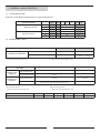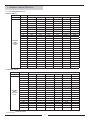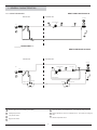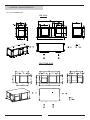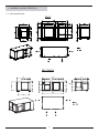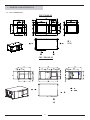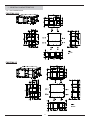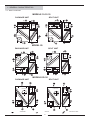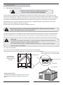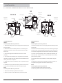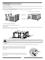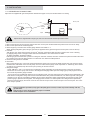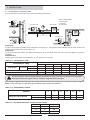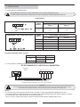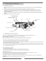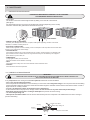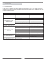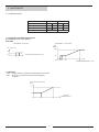
1
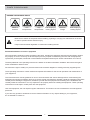
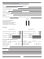
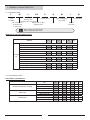
Installation, operating
and maintenance
FLATAIR R410A FMC-H/ FIC-H/ FSC-H
Providing indoor climate comfort
MIL115E-1011 10-2011
Original manual translation
WARNING: Read this manual before installation, reparation o maintenance works.
TABLE OF CONTENTS
POINTS TO BEAR IN MIND PAGE 2
DATA PAGE FOR COMMISSIONING UNIT PAGE 3
1.- GENERAL CHARACTERISTICS
PAGE
4
4-5
5
6
7-8
9-14
15
1.1.- PHYSICAL DATA
1.2.- ELECTRICAL DATA
1.3.- OPERATING LIMITS
1.4.- FAN PERFORMANCES
1.5.- PIPING DRAWINGS
1.6.- UNIT DIMENSIONS
1.7.- DUCT POSITION
2.- INSTALLATION
2.1.- PRELIMINARY PREPARATIONS
2.2.- UNIT ACCEPTANCE
2.3.- OPTIONAL OPERATIONS PRIOR TO UNIT INSTALATION
2.4.- UNIT LOCATION
2.5.- INSTALLATION CLEARANCES
2.6.- DRAINS
2.7.- REFRIGERANT CONNECTIONS
2.8.- ELECTRICAL CONNECTIONS
3.- COMMISSIONING AND OPERATION
3.1.- PRELIMINARY CHECKS
3.2.- PRELIMINARY CHECKS AT FIRST INSTALLATION
PAGE
16
16
18
18
18
19-20
21
PAGE
22
22-23
4.- MAINTENANCE
PAGE
24
24-25
26
27
4.1.- PREVENTIVE MAINTENANCE
4.2.- CORRECTIVE MAINTENANCE
4.3.- FAILURE DIAGNOSIS
4.4.- REGULATION
Lennox have been providing environmental solutions since 1895, our COMPACTAIR range continues to meet the standards that have made LENNOX a household name. Flexible design solutions to meet YOUR needs and uncompromising attention to detail. Engineered to last, simple to maintain and Quality that comes as standard.
For information on local contacts at www.lennoxeurope.com.
All the technical and technological information contained in this manual, including any drawing and technical descriptions provided by us, remain the property of Lennox and must not be used (except in the operation of this product),
reproduced, issued to or made available to third parties without the prior written agreement of Lennox.
POINTS TO BEAR IN MIND
DANGER AND WARNING SIGNS
Abrasive
surfaces
Low
temperatures
High
temperatures
Risk of injury by
moving objects
Electrical
voltage
Risk of injury by
rotating objects
ELECTRICAL CONNECTIONS
Make sure to switch off the power before installing, repairing or carrying out maintenance on the unit,
in order to prevent serious electrical injury.
Keep local and national legislation in mind when installing the unit.
Standard Guidelines to Lennox equipment
All technical data contained in these operating instructions, including the diagrams and technical description remains
the property of Lennox and may not be used (except for the purpose of familiarizing the user with the equipment),
reproduced, photocopied, transferred or transmitted to third parties without prior written authorization from Lennox.
The data published in the operating instructions is based on the latest information available. We reserve the right to
make modifications without notice.
We reserve the right to modify our products without notice without obligation to modify previously supplied goods.
These operating instructions contain useful and important information for the smooth operation and maintenance of
your equipment.
The instructions also include guidelines on how to avoid accidents and serious damage before commissioning the
equipment and during its operation and how to ensure smooth and fault-free operation. Read the operating instructions
carefully before starting the equipment, familiarize yourself with the equipment and handling of the installation and
carefully follow the instructions. It is very important to be properly trained in handling the equipment. These operating
instructions must be kept in a safe place near the equipment.
Like most equipment, the unit requires regular maintenance. This section concerns maintenance and management
personnel.
If you have any queries or would like to receive further information on any aspect relating to your equipment,
do not hesitate to contact us.
DATA PAGE FOR UNIT COMMISSIONING
UNIT:
SERIAL Nr:
CONTROL PANEL IDENTIFICATION CODE:
INSTALLATION ADDRESS:
INSTALLER:
INSTALLER TEL:
INSTALLER ADDRESS:
DATE OF COMMISSIONING:
CHECKS:
SUPPLY VOLTAGE:
RATED VOLTAGE OF THE UNIT:
YES NO
UNIT ON SHOCK ABSORBERS
DRAINAGE WITH TRAP
MAIN POWER SUPPLY CONNECTION
CONTROL PANEL CONNECTION
COMPRESSOR OIL LEVEL INDICATOR
DATA INPUT:
COOLING CYCLE
Air intake temperature to the outdoor coil:
Air output temperature to the outdoor coil:
HEATING CYCLE
1
2
1
2
ºC
ºC
ºC
ºC
Air intake temperature to the outdoor coil:
Air output temperature to the outdoor coil:
High pressure:
circuit 1
circuit 2
High pressure:
circuit 1
circuit 2
Low pressure:
circuit 1
circuit 2
Low pressure:
circuit 1
circuit 2
ELECTRIC POWER CONSUMPTION (Amps)
Compressor 1
Compressor 3
Outdoor fan section 1
Compressor 1
Compressor 2
Compressor 3
Outdoor fan section 1
Outdoor fan section 2
Outdoor fan section 2
Options installed:
Comments:
Compressor 2
1
2
1
2
ºC
ºC
ºC
ºC
1.- GENERAL CHARACTERISTICS
1.1.- PHYSICAL DATA
F
M
C
015
S
N
C: Cooling only
S: One Circuit
H: Heat pump
X: Cooling only / Heat pump
M: Compact unit
Approximate cooling
S: Outdoor unit
capacity in kW
I: Indoor unit
M
Unit
FLATAIR
1
M
Type of refrigerant
M: R-410A
---
M: 400V/3/50
Number
of revision
FMC: Cooling only unit R-410A.
FMH: Heat pump unit R-410A.
WEIGHTS OF THE UNITS AND OPTIONS
MODELS
010
012
015
020
025
030
Cooling only FMC
170
174
250
268
322
338
Heat pump FMH
175
179
255
273
327
343
Package unit
Outdoor unit
Net weight
Kg.
Cooling only FSC
112
116
165
159
202
208
Heat pump FSH
117
121
170
164
207
213
Cooling only FIC
58
58
85
109
121
131
Heat pump FIH
58
58
85
109
121
131
Free-cooling 1 damper
12
12
12
14
15
15
Free-cooling 2 dampers
24
24
24
28
30
30
Electrical heater
7
7
7
7
8
8
Indoor unit
Opcions
1.2.- ELECTRICAL DATA
ELECTRICAL CONSUMPTION
UNIT
PACKAGE UNIT (INDOOR+ OUTDOOR)
INDOOR UNIT
OUTDOOR UNIT
10
230V I
10
12
15
20
25
30
Maximum power (KW)
5,5
5,3
6,6
7,8
10,4
12,6
14,2
Maximum current (A)
31,7
13,7
16,0
18,6
23,6
30,0
31,0
Starting current (A)
90,2
34,1
39,7
49,0
75,3
82,3
86,9
Maximum power (KW)
0,4
0,4
0,4
0,8
1,0
1,3
1,3
Maximum current (A)
2,6
2,6
2,6
2,8
4,3
4,3
4,3
Starting current (A)
1,7
1,7
1,7
1,8
2,8
2,8
2,8
Maximum power (KW)
5,1
4,9
6,1
7,0
9,4
11,3
13,0
Maximum current (A)
29,1
11,1
13,4
15,8
19,3
25,7
26,7
Starting current (A)
87,6
31,5
37,1
46,2
71,0
78,0
82,6
1.- GENERAL CHARACTERISTICS
1.2 .- ELECTRICAL DATA
Electrical consumptions to add to the unit indoor and to the set
10
230V I
10
Standard
3
3
4,5
7,5
Medium
6
6
6
9
9
9
12
Standard
13,0
7,5
11,3
18,8
Medium
26,1
15
15
22,5
High
-
22,5
22,5
30
ELECTRICAL HEATER
Maximum power (KW)
High
Maximum current (A)
12
15
20
25
30
1.3.- OPERANTING LIMITS
OPERATING LIMITS (COOLING ONLY)
MAXIMUM TEMPERATURES
MINIMUM TEMPERATURES
32ºC BS / 23ºC BH
21ºC BS / 15ºC BH
Table 1
+15ºC UNIDAD ESTÁNDAR
0ºC (*) -15ºC (**)
INDOOR TEMPERATURE
COOLING CYCLE OPERATION
OUTDOOR TEMPERATURE
(*) With option kit low temperature 0ºC.
(**) With option kit low temperature -15ºC.
OPERATING LIMITS
MAXIMUM TEMPERATURES
MINIMUM TEMPERATURES
32ºC BS / 23ºC BH
21ºC BS / 15ºC BH
Table 1
+15ºC STANDARD UNIT
0ºC (*) -15ºC (**)
27ºC BS
15ºC BS
25ºC (With 20º indoor temperature. Models 10-15-20-30)
23ºC (With 20º indoor temperature. Models 12-25)
-12ºC
(HEAT PUMP)
COOLING CYCLE
OPERATION
HEATING CYCLE
OPERATION
INDOOR TEMPERATURE
OUTDOOR TEMPERATURE
INDOOR TEMPERATURE
OUTDOOR TEMPERATURE
DB: Dry bulb temterature
WB: Wet bulb temperature
(*) Active CL40 parmeter to operate at 0º
(**) With option kit low temperature -15ºC.
Table 1
10
12
15
20
25
30
Maximum outdoor temperature
45
43
45
44
44
41
1.- GENERAL CHARACTERISTICS
1.4.- FAN PERFORMANCES
INDOOR UNITS
Airflow (m3/h)
Available
static
pressure
(Pa)
UNITS
10
12
15
20
25
30
0
2350
2300
3575
4850
5750
5500
10
2275
2250
3495
4785
5730
5455
20
2240
2200
3410
4715
5705
5405
30
2190
2150
3330
4645
5670
5350
40
2140
2100
3250
4575
5630
5285
50
2080
2040
3170
4500
5580
5220
60
2025
1975
3095
4425
5530
5140
70
1975
1925
3020
4345
5470
5060
80
1925
1860
2945
4260
5405
4965
90
1840
1800
2875
4175
5330
4870
100
1775
1730
2800
4090
5250
4765
110
1625
1650
2735
4000
5165
4655
120
1500
2665
3910
5075
4540
130
2600
3815
4975
4415
140
2535
3720
4870
4285
150
2470
3620
4755
4150
160
2410
3520
4640
4005
170
3415
4515
3855
180
3310
4380
3695
190
3200
4245
200
3090
4100
210
3945
220
3790
230
3625
240
3455
OUTDOOR UNITS
Airflow (m3/h)
Available
static
pressure
(Pa)
UNITS
10
12
15
20
25
30
0
3500
3400
4500
5650
6000
5850
10
3410
3325
4460
5550
5920
5755
20
3300
3160
4410
5450
5840
5665
30
3190
3075
4360
5350
5760
5575
40
3080
2980
4310
5250
5680
5485
50
2970
2890
4250
5150
5600
5400
60
2840
2790
4190
5050
5520
5315
70
2700
2690
4125
4945
5445
5235
80
2560
2580
4055
4840
5365
5155
90
2410
2400
3980
4735
5290
5075
100
2350
5000
3905
4630
5210
110
3825
4525
5135
120
3740
4420
5060
130
4315
4985
140
4205
4910
150
4095
4835
160
4760
Nominal airflow
1.- GENERAL CHARACTERISTICS
COOLING ONLY UNITS 10-12-15
1.8.- PIPING DRAWINGS
INDOOR UNIT
OUTDOOR UNIT
Fan motor
Scroll compressor
LP
HP
PT
Fan
CH
IS
Coil
Coil
Orifice
OS
OPTION ELEMENT
HEAT PUMP UNITS 10-12-15
INDOOR UNIT
OUTDOOR UNIT
Fan motor
LP
Scroll compressor
HP
4-way valve
PT
Fan
IS
Coil
Coil
Suction
Acumulator
Orifice
Filter drier
Orifice
OS
Pressure gauge. (5/16” to be fitted by the installer).
CH
Crank case heater. (Low ambient 0ºC or -15ºC option for cooling only units).
IS
Liquid-gas pipe sensor
PT
Pressure transducer (Low ambient 0ºC or -15ºC option for cooling only units).
LP
Low pressure switch
OS
Outdoor temperature sensor
HP
High pressure switch
1.- GENERAL CHARACTERISTICS
HEAT PUMP UNITS 20-25-30
1.8.- PIPING DRAWINGS
OUTDOOR UNIT
INDOOR UNIT
Fan motor
Scroll compressor
LP
HP
PT
Fan
CH
IS
Coil
Coil
OS
Expansion valve
Filter drier
(ELEMENTO OPCIONAL)
OPTION ELEMENT
HEAT PUMP UNITS 20-25-30
OUTDOOR UNIT
INDOOR UNIT
Fan motor
Fan
LP
Scroll compressor
HP
4-way valve
PT
Fan
IS
Coil
Coil
Suction
Acumulator
Scroll compressor
OS
Expansion valve
Filter drier
Filter drier
Expansion valve
Check valve
Check valve
Pressure gauge. (5/16” to be fitted by the installer).
CH
IS
Liquid-gas pipe sensor.
PT
LP
Low pressure switch.
OS
HP
High pressure switch.
Crank case heater. (Low ambient 0ºC or -15ºC option for cooling only units).
Pressure transducer, circuit 1.(Low ambient 0ºC or -15ºC option for cooling only
units).
Outdoor temperature sensor
1.- GENERAL CHARACTERISTICS
1.5.- UNIT DIMENSIONS
FIX 10-12
FSC / FSH 10-12
1.- GENERAL CHARACTERISTICS
1.5.- UNIT DIMENSIONS
FIX 15
FSC / FSH 15
10
1.- GENERAL CHARACTERISTICS
1.5.- UNIT DIMENSIONS
FIC / FIH 20
FSC / FSH 20
11
1.- GENERAL CHARACTERISTICS
1.5.- UNIT DIMENSIONS
FIC / FIH 25-30
FSC / FSH 25-30
12
1.- GENERAL CHARACTERISTICS
1.5.- UNIT DIMENSIONS
FMC/FMH 10-12
FMC/FMH 15
13
1.- GENERAL CHARACTERISTICS
1.5.- UNIT DIMENSIONS
FMC/FMH 20
FMC/FMH 25-30
14
1.- GENERAL CHARACTERISTICS
1.5.- DUCT POSITION
MODELS 10-12-15
SPLIT UNIT
PACKAGE UNIT
OUTDOOR
FAN
OUTDOOR
FAN
INDOOR
FAN
INDOOR
FAN
E.H.
E.H.
O
O
UT
IL
R
CO
IL
COMPRESSOR
IN
IN
DO
IL
COMPRESSOR
O
CO
CO
OR
DO
DO
R
CO
O
OR
DO
IL
UT
MODEL 20
SPLIT UNIT
PACKAGE UNIT
COMPRESSOR
COMPRESSOR
IL
R
O
O
TD
IL
CO
R
O
E.H.
O
TD
CO
E.H.
U
U
IL
O
DO
IN
OR
DO
MODELS 25-30
PACKAGE UNIT
COMPRESSOR
OUTDOOR
FAN
IN
OUTDOOR
FAN
OR
CO
CO
IL
O
INDOOR
FAN
INDOOR
FAN
SPLIT UNIT
INDOOR
FAN
COMPRESSOR
OU
E.H.
OU
OPTION
15
CO
IL
IN
OUTDOOR
FAN
DO
O
R
IN
DO
O
IL
R
CO
STANDARD
R
IL
CO
OUTDOOR
FAN
CO
I
L
OO
R
OO
TD
TD
E.H.
INDOOR
FAN
ELECTRICAL BOX
2.- INSTALLATION
2.1.- PRELIMINARY PREPARATIONS
All INSTALLATION, SERVICE and MAINTENANCE work
must be carried out by QUALIFIED PERSONNEL.
The unit must be transported in a HORIZONTAL POSITION on its metal mounting frame. Any other position may
cause serious damage to the machine. When the unit is received, it should be checked to assure that it has received
no shocks or other damage, following the instructions on the packaging. If there is damage, the unit may be rejected
by notifying the LENNOX Distribution Department and stating why the machine is unacceptable on the transport
agent’s delivery note. Any later complaint or claim made to the LENNOX Distribution Department for this type of
damage cannot be considered under the Guarantee.
Sufficient space must be allowed to facilitate installation of the unit.
When positioning the unit, be sure that the Rating Plate is always visible since this data
will be necessary to ensure correct maintenance.
The units are designed to be installed with ducts designed by qualified technical staff. The joints to be used between
ducts and openings in the unit should be Elastic Joints. Avoid the use of BYPASS joints between the extraction air
and input air. The structure where the unit is placed must be able to support the weight of the unit during operation.
Defrosting:
To avoid ice accumulation in the driptray , it may be necessary to install an electrical heater and
inside the drainage connection , to drain correctly the water
The drainage must be always accessible through the indoor part , in order to remove easily the
dirty than may be accumulated.
2.2.- UNIT ACCEPTANCE
All the units have metal bedplate profiles and wooden blocks for transportation.
These wooden blocks must be removed when positioning the unit in its final position.
Para extraer los tacos de transporte, quite el
tornillo y deslice el taco por el perfil metálico
Bedplate profile
PLACEMENT OF
BEDPLATE AND
TRANSPORTATION
BLOCKS
Securing screw
Wood block
Use separators
Wood block
How to hoist the unit
If unloading and placement require the use of a crane,
then secure the suspension cables as shown in the
figure.
16
2.- INSTALLATION
2.3.- OPTIONAL OPERATIONS PRIOR TO UNIT INSTALATION
20
Service panel
10-12-15
Supply panel
Service panel
with opening
Supply panel
with opening
25-30
Intake opening
Supply panel
Air filter panel
Supply panel
with opening
with opening
Service panel
Supply panel
with opening
Intake opening
Air filter panel
Service panel
Service panel
Air filter panel
OUTDOOR SECTION
INDOOR SECTION
SUPPLY
SUPPLY
From the position A0 to the position A1
From the position C0 to the position C1
1.-Remove the ceiling of the unit, the supply panel with opening and
1.-Remove the ceiling of the unit, the supply panel with opening and the
the service panel.
service panel.
2.-Remove the motor-fan assembly from the unit unscrewing the
2.-Remove the motor-fan assembly from the unit unscrewing the suppor-
supports from the base, and throwing away the extension collar, if
ts from the base, and throwing away the extension collar, if there is one.
there is one.
3.-Unscrew the supports taht have been left on the fan-motor assembly.
3.-Unscrew the supports taht have been left on the fan-motor
4.-Turn the fan-motor assembly to its new position 90º horizontally and
assembly.
180º on its shaft. The motor should now be accessible from the service
4.-Turn the fan-motor assembly to its new position 90º horizontally
panel in this new position.
and 180º on its shaft. The motor should now be accessible from the
5.-Screw down the fan-motor assembly in its new position using the
service panel in this new position.
supports.
5.-Screw down the fan-motor assembly in its new position using the
6.-Assembly the supply panel with opening and the service panel in its
supports.
new position, taking special care with the weather striping.
6.-Assembly the supply panel with opening and the service panel in
INLET:
its new position, taking special care with the weather striping.
From the position D0 to the position D1
INLET:
1.-Remove the intake air filter and the service panel.
From the position B0 to the position B1
2.-Switch the position of the air filter and service panels.
1.-Remove the intake opening and the service panel.
2.-Switch the position of the intake opening and service panels.
17
2.- INSTALLATION
2.4.- UNIT LOCATION
The bedplate is made up of three galvanized metal channels, capable of withstanding the weight of the units whether hung from the
ceiling or mounted on the floor.
If the unit is floor mounted, then the profiles should be isolated with shock absorbing material such as anti-vibration or pads. Keep in
mind that fans rotate at approximately 850 rpm.
If the unit is hung, M-10 threaded rods should be used along with shock absorbing ceiling supports.
UNIT HUNG WITH RODS
UNIT INSTALLED ON SHOCK ABSORBERS
Ceiling supports
(shock absorbers)
Floor supports
(shock absorbers)
2.5.- INSTALLATION CLEARANCES
Clearance around the unit for service and maintenance
SERVICE SPACE
Space should be left free for access or servicing, to ease the installation of cables, drainage connections, electric installation and
cleaning filters, as well as easy access to the unit.
1m
1m
1m
1m
For the unit with option FREECOOLING, it should be kept in mind that bedplate anchors cannot be used to hang
the unit.
2.6.- DRAINS
All the indoor and outdoor sections of these units have a 3/4” steel threaded drain pipe welded to the condensation tray.
Drainage pipes will be fitted for each tray through a siphon with a height
difference of 80 mm. to avoid drainage problems from the depression formed
by the fans. The pipes should have an inclination of 2% to ease drainage of
condensation.
Mín. 80 mm.
2%
Also slightly tip the unit (2%) toward the drainage side. Check that the condensation
trays are clean and free from dirt and other debris from the works and that water
drains correctly.
Inspection and cleaning stopper
18
2%
2.- INSTALLATION
2.7.- REFRIGERANT CONNECTIONS
Split units are supplied with gas and liquid lines sealed with copper covers, and located 60mm from casing.
Service ports
Gas
Cupper cover
Terminal
block
Brazing
Liquid
Split units are supplied with nitrogen gas, this must be removed and then proceed as folow:
1. Remove the nitrogen gas through the high and low 5/16” service ports located inside and provide a low vacuum for safety.
2. Remove the caps from the connecting lines.
3. Braze the piping connection lines. Select piping diameter from table 2.7.1.
(When brazing refrigerant pipes, nitrogen gas must be supplied into the pipes through the service ports to remove the air).
4. Leak test:
Add nitrogen gas, check that a pressure of 5 kg/cm2 has been reached and that there are no leaks in the circuit or brazing
by applying soapy water to the pipes which will cause the bubbles to form where there are leaks.
To detect small leaks, proceed as follows:
Add nitrogen gas and check that a pressure of 25 kg/cm2 has been reached, there are no leaks if the pressure remains the same for at least 24 hours and the final pressure is not less than 10% below the initial pressure.
5. Ensure that the gas line is insulated.
6. Evacuation:
Remove the nitrogen gas, connect the gauge manifold and vacuum pump to both the liquid and gas lines, fully open the gauge
manifold valve and switch on the vacuum pump. Check to make sure the gauge shows a pressure of -750mm Hg. Once a level
of -750mm Hg is reached, keep the vacuum pump running for at least one hour.
7. Refrigerant charge:
- Check TABLE 3.1. and 3.2. for the amount of refrigerant charge, depending on the length and size of the pipe connections.
- Disconnect the vacuum pump and connect to the refrigerant-charging bottle. Open the charging pump and purge the air from
the hose at the pressure gauge manifold.
- Set up the amount of additional refrigerant on the weighing scale, open the high pressure and charged in the liquid state. If the
total amount of refrigerant charge has not been reached because the pressure is balanced, turn off the high side of the gauge
manifold, turn on the unit, and add the remaining amount of the refrigerant charge required slowly through the low side of the
pressure gauge. (With R-410A refrigerant, the charging bottle must be in a vertical position and charged in the liquid state).
Close the pressure gauge, disconnect it from the from the service port of the unit and fit caps on the service ports. The unit is
then ready to operate.
During installation operations, keep gas and liquid pipes covered, in order to prevent humidity and dirt,
get into them.
Take special concern about refrigerant pipes are isolated.
Avoid collapse on line installation.
19
2.- INSTALLATION
2.7.- REFRIGERANT CONNECTIONS
To locate the outdoor and the indoor units, refer to the following information:
OUTDOOR UNIT
INDOOR UNIT
A,B,C: Units positions
L: Total length
1: Gas line
2: Liquid line
OUTDOOR UNIT
INDOOR UNIT
OUTDOOR UNIT
INDOOR UNIT
POSITION A:
A syphon suction must be installed on the vertical line of the gas line 1, and syphons must be installed every 8 meters upward. The
minimum speed suction must not be below 6 m/s.
POSITION B:
Tip the lines toward the outdoor unit. Make special attention to the line length longer than 10m and avoid collapse on pipe lines
installation.
DISPOSICIÓN C:
Install a syphon at the base of the vertical line, no more syphons are necessary.
TABLE 2.7.1.: REFRIGERANT LINES
REFRIGERANT LINES
Liquid
Total length
0 to 30m
Gas
Maximum vertical line length (m)
Maximum number of bends
10
3/8”
3/4”
15
12
UNIT-MODEL
15
20
1/2”
1/2”
7/8”
7/8”
15
15
12
12
12
3/8”
3/4”
15
12
25
5/8”
1 1/8”
15
12
30
5/8”
1 1/8”
15
12
For other positions and lines lengths between 30 and 50m or longer, consult the commercial-technical department, pipe dimensions, syphon suction, isolations, refrigerant load, line lengths.
Split units are supplied with nitrogen gas.The installer should remove this gas and charge the units with the charge of refrigerant
R410A , shown in the table 2.7.2 plus the charge by additional meter shown in the table 2.7.3.
TABLE 2.7.2.: REFRIGERANT CHARGE
MODELS
Refrigerant charge R-410A
10
12
15
20
25
30
Cooling only
2,14
2,57
3,55
4,46
5,38
6,15
Heat pump
2,5
2,93
4
4,9
6,3
7
TABLE 2.7.3.: EXTRA REFRIGERANT CHARGE R410A BY METER
Liquid
Gas
3/8”
3/4”
57
1/2”
7/8”
108
5/8”
1 1/8”
177
20
g/m
2.- INSTALLATION
2.7.- ELECTRICAL CONNECTIONS
- BEFORE MAKING ANY ELECTRICAL CONNECTIONS, ENSURE THAT ALL CIRCUIT BREAKERS ARE OPEN.
- IN ORDER TO MAKE THE ELECTRICAL CONNECTIONS, FOLLOW THE ELECTRICAL DIAGRAM SUPPLIED WITH THE UNIT.
POWER SUPPLY
POWER SUPPLY 230V SINGLE PHASE UNITS
Nº DE CABLES X SECCIÓN (mm2)
UNIDAD
MODELO
Alimentación sin batería
eléctrica
Alimentación con batería
eléctrica
3x4
3 x 16
10
POWER SUPPLY 400V THREE-PHASE UNITS
UNIDAD
MODELO
Nº DE CABLES X SECCIÓN (mm2)
Alimentación sin batería
eléctrica
Alimentación con batería
eléctrica
10
5 x 2,5
5x4
12
5 x 2,5
5x4
15
5x4
5x6
20
5x4
5 x 10
25
5x6
5 x 10
30
5x6
5 x 10
VOLTAGE OPERATING LIMITS: 342-462V
MODELS
10
12-15-20-25-30
VOLTAGE
LIMIT
230V-1Ph-50 Hz
198-264 V
400V-3Ph-50 Hz
342-462 V
400V-3Ph-50 Hz
2.7.- ELECTRICAL CONNECTIONS
DC 40 THERMOSTAT, ELECTRICAL CONNECTION
CONTROL
PANEL
GND TX+ TX- GO
90
GND
TX+
TX-
91
92
93
G
94
GO
G
DC 40
2 x Shielded twisted pairs AWG 20. 100 m maximum.
1x Shielded twisted pair AWG20 + 2 x 1,5 mm. 200m maximum.
IMPORTANT
THE SHIELDED CONNECTING CABLE BETWEEN THE CONTROL PANEL AND THE UNIT MUST BE SEPARATED FROM ANY OTHER
TYPE OF ELECTRICAL WIRING. CONNECT IT TO THE ELECTRIC PANEL LOCATED IN THE OUTDOOR UNIT.
NOTES:
- For securing and connecting the Control Panel, consult the control panel Manual supplied with the unit.
- Connection between the DC40 and the unit must be made using shielded twisted pair cables (where the screens
are connected to the control panel and the unit Electrical box).
- The Tx+ and Tx- polarity must strictly comply with the electrical diagram supplied with the unit.
21
3.- COMMISSIONING AND OPERATION
3.1.- PRELIMINARY CHECKS
. Check that drain pipe connections and their fixtures are secure and that the level of the unit is tipped toward the
drain.
2. Inspect the state of the ducts and grilles 8clean and open grilles, no breaks in the duct, etc.)
3. Check that the power supply is the same as stated on the firm plate which is in agreement with the electrical
diagram for the unit and that cable sizes are correct. Check that tightness of the electrical connections to their
terminals and to ground.
4. Inspect the air filter, which should be in its housing and correctly positioned (the metal grille should be toward the
inside)
5. Check with your hand that the fans turn freely.
INDOOR SECTION
OUTDOOR SECTION
Air filter
Return air duct
Supply air duct
Outdoor air inlet duct
Trap
Fan access
Flexible joint at openings
Trap
Drain pipe
Outdoor discharge duct
Power supply
3.2.- PRELIMINARY CHECKS AT STARTUP
To start the unit, follow the instructions given in the User Manual for the control supplied with the unit
(requiring operation in any of the modes, cooling, heating, or automatic).
After a time delay, the unit will start.
With the unit operating, check that the fans are turning freely and in the correct direction.
CHECK THAT THE COMPRESSOR IS ROTATING IN THE CORRECT DIRECTION.
- If you have the option phase rotation indicator, use it to check the correct rotation.
- If you do not have three phase return lock, check the correct direction of rotation. The suction pressure decreases and the discharge
pressure increases when the compressor is started.
- If the connection is incorrect, rotation will be reversed, causing a high noise level and a reduction in the amount of current consumed.
If this occurs, the compressor’s internal protection system will operate to shut down the unit. The solution is to disconnect, reverse
two of the phases and connect again.
WITH OPERATING UNIT, CHECK:
- Low pressure and high pressure.
- Use the evaporating and liquid temperature to calculate superheat and subcooling.
- Adjust the refrigerant charge and/or expansion valve according to the preceding values.
COMPRESSOR OIL LEVEL
The oil level must always be checked. When the compressor is at rest, the level should be between 1/4 and 3/4
in the sight glass, while when running the level should be between 3/4 and full.
In the event of having to add oil, remember the type of oil is synthetic POE.
The original oil charge in the compressor is ICI Emkarate RL32-3MAF. This type of oil must also be used when replacing the oil
completely.
When only topping up, RL32-3MAF or Mobil EAC Artic 22C can be used.
22
3.- COMMISSIONING AND OPERATION
3.2.- PRELIMINARY CHECKS AT FIRST INSTALLATION
The unit must be installed in accordance with local safety codes
andregulations and can only be used in a well ventilated area.
Please readcarefully the manufacturer’s instructions before starting this unit
All work on the unit must be carried out by a qualified and
authorised employee.
Non-compliance with the following instructions may result in injury or serious accidents.
Work on the unit:
The unit shall be isolated from the electrical supply by disconnection and locking using the main isolating switch. Workers
shall wear the appropriate personal protective equipment (helmet, gloves, glasses,etc.).
Electrical system:
Electrical connections can become loose during transport. Please check them before starting-up the unit Compressors with
specific rotation direction. Check the correct rotation direction
of the fan before closing the compressor circuit breakers. If the
direction is incorrect, the phases must be reversed at the head
of the main switch. Work on electric components shall be performed with the power off (see below) by employees having valid
electrical qualification and authorisation.
Refrigerating circuit(s):
After more than 12 hours of power cut, the cranckcase heater
(compressor) should be powered for 5 hours before any return
to service. Non-compliance with this instruction can cause deterioration of the compressors.
Monitoring of the pressures, draining and filling of the system
under pressure shall be carried out using connections provided
for this purpose and suitable equipment.
23
To prevent the risk of explosion due to spraying of coolant and
oil, the relevant circuit shall be drained and at zero pressure before any disassembly or unbrazing of the refrigerating
parts takes place.
There is a residual risk of pressure build-up by degassing the
oil or by heating the exchangers after the circuit has been
drained. Zero pressure shall be maintained by venting the
drain connection to the atmosphere on the low pressure side.
The brazing shall be carried out by a qualified brazier. The
brazing shall comply according to code ASME section IX following the procedures specifi In order to maintain CE marking
compliance, replacement of components shall be carried out
using spare parts, or using parts approved by Lennox.
Only the coolant shown on the manufacturer’s nameplate
shall be used, to the exclusion of all other
products (mix of coolants, hydrocarbons, etc.).
CAUTION:
In the event of fire, refrigerating
circuits can cause an explosion
and spray coolant gas and oil.
4.- MAINTENANCE
4.1.- PREVENTIVE MAINTENANCE
PREVENTIVE MAINTENANCE PREVENTS COSTLY REPAIRS.
THIS REQUIRES PERIODIC INSPECTIONS:
- AIR FILTER :
The air filter can be removed through the side by sliding it over the rail or downwards.
(See figure).
For downwards removal, remove the two profiles that support it (depending on the model)
which are under the filter guide rail and screwed onto the unit.
DOWN REMOVAL
SIDE REMOVAL
- GENERAL STATE OF THE CASING:
Furniture, paint, damage due to shocks, rust spots, levelling and supporting, condition of the shock
absorbers, if installed, screwed panels, etc.
- ELECTRICAL CONNECTIONS:
State of hoses, tightness of screws, earthing, current consumption of the compressor and fans and check
that the unit is receiving the correct voltage.
- COOLING CIRCUIT:
Check that the pressures are correct and that there are no leaks. Check that there is no damage to the
pipe insulation, that the condition of the coils is good and that they are not blocked by bits of paper or
plastic drawn in by the air flow, etc.
- COMPRESSOR:
If a sight glass is fitted, check the oil level.
Check the condition of the silentbloc mountings.
- FANS:
Check that fans turn freely and in the correct direction without excessive noise.
- CONTROL:
Check Set Points and normal operation.
4.2.- CORRECTIVE MAINTENANCE
IMPORTANT
MAKE SURE THAT THE UNIT IS FULLY DISCONNECTED FROM THE POWER SUPPLY WHEN CARRYING OUT
ANY TYPE OF WORK ON THE MACHINE.
If any component in the cooling circuit is to be replaced, follow these recommendations:
- Always use original replacement parts.
- If the component can be isolated, it is not necessary to remove the entire refrigerant charge, if the component cannot be isolating
and the refrigerant charge is removed, it should be removed through the Schrader valves located in the outdoor section. Create a
slight vacuum as a safety measure.
- Regulation prohibits the release of refrigerant into the atmosphere.
- If cuts must be made in the pipe work, use pipe cutters. Do not use saws or any other tools that produce filings.
- All brazing must be carried out in a nitrogen atmosphere to prevent corrosion forming.
- Use silver alloy brazing rod.
- Take special care that the flame from the torch is directed away from the component to be welded and cover with a wet rag to
prevent overheating.
Direction of the flame
Wet rag
Silver alloy welding rod
Nitrogen
Component to be welded
24
4.- MAINTENANCE
4.2.- CORRECTIVE MAINTENANCE
- Take very special care if 4-way or check valves are to be replaced since these have internal components that are very heat-sensitive such as
plastic, teflon, etc.
- If a compressor is to be replaced, disconnect it electrically and un-braze the suction and discharge lines. Remove the securing
screws and replace the old compressor with the new one. Check that the new compressor has the correct oil charge, screw it to
the base and connect the lines and electrical connections.
- Evacuate above and below through the Schrader valves of the outdoor unit until -750 mm Hg is reached.
Once this level of vacuum has been reached, keep the pump running for at least one hour.
DO NOT USE THE COMPRESSOR AS A VACUUM PUMP.
- Charge the unit with refrigerant according to the data on the Rating Plate for the unit and check that there are no leaks.
PRECAUTIONS TO BE TAKEN WHEN USING OF R-410A Refrigerant:
R-410A refrigerant is used in the unit; the following standard precautions for this gas should therefore be taken:
- The Vacuum Pump must have a Check Valve or Solenoid Valve fitted.
- Pressure Gauges and Hoses for exclusive use with R-410A Refrigerant should be used.
- Charging should be carried out in the Liquid Phase.
- Always use scales to weigh-in charge
- Use the Leak Detector exclusive for R-410A Refrigerant.
- Do not use mineral oil, only synthetic oil to ream, expand or make connections.
- Keep pipes wrapped before using them and be very thorough about any possible dirt (dust, filings, burrs, etc.).
- When there is a leak, collect what remains of the charge, create a vacuum in the unit and completely recharge with new R410A Refrigerant.
- Brazing should always be carried out in a nitrogen atmosphere.
- Reamers should always be well sharpened.
25
4.- MAINTENANCE
4.3.- FAILURE DIAGNOSIS
In case of failure or malfunction of the unit, the display on the control panel will show an error or alarm warning which
is explained in the control panel manual. Nevertheless, whenever there is a unit fault, the unit should be shut down and
our service technicians consulted.
FAULT
UNIT DOES NOT START
UNIT STOPS DUE TO HIGH
PRESSURE DURING THE
COOLING CYCLE
POSSIBLE CAUSES
POSSIBLE SOLUTIONS
Fault in the power supply or insufficient voltage.
Connect the power supply or check the voltage.
Circuit breakers have opened.
Reset.
Power cable or control panel cable is defective.
Inspect and correct.
High pressure switch is defective.
Check cut-off pressure switch or replace
pressure switch if necessary.
Check for voltage, inspect the motor and turbine
or replace if necessary..
Outdoor fan is not working.
Outdoor fan turns in the wrong direction.
Reverse the power phases.
Outdoor coil is dirty or clogged for passing air.
Inspect and clean.
Excess refrigerant charge.
Remove the charge and charge according to the
data on the rating plate.
UNIT STOPS DUE TO HIGH PRESSUThe same causes and solutions as the cold cycle but with reference to the coils and indoor fan.
RE DURING THE HEATING CYCLE
Indoor fan is not working.
Check the cut-off pressure with a pressure gauge
and replace the pressure switch if necessary.
Check for voltage and inspect the motor, turbine
and replace if necessary.
Indoor fan turns in the wrong direction.
Reverse the power phases.
Lack of refrigerant. Leak.
Correct leak, create vacuum and charge.
Dirty air filter.
Inspect and clean
Clogged cooling circuit.
Dirty filter drier.
Inspect and correct or change the filter drier.
Low pressure switch defective.
UNIT STOPS DUE TO LOW
PRESSURE
UNIT STARTS AND STOPS IN
SHORT CYCLES
LOAD AND ABNORMAL NOISE IN
THE COMPRESSOR (SCROLL)
Compressor overcharged.
Inspect suction and discharge pressure values
and correct.
Compressor cuts off due to Klixon.
Check input voltage and voltage drop.
Lack of refrigerant.
Correct leak and replace.
Power supply phases inverted.
(three-phase compressor).
Check and reverse power phases.
26
4.- MANTENANCE
4.4.- REGULACTION
COOLING
LP
HP
HEATING
RESET
SET
SET
RESET
3,5
4,5
1,7
2,7
43
34
43
outdoor fan speed
regulation
PT
34
defrost
Tables values in bar g.
1.- OUTDOOR FAN SPEED REGULATION
(Low ambient 0ºC or - 15ºC option)
CMC,CMH
LOW AMBIENT -15ºC OPTION
LOW AMBIENT 0ºC OPTION
FAN
SPEED
CFM (Fan speed)
100%
ON
OFF
20
24
CONDENSATION PRESSURE (bar g)
40%
0%
18 18.5
20
2.- DEFROST
- Start: suction pressure < pressure of starting defrost, for 60 sec.
- End: 30 bar or more than 8 minutes from the beginning
of defrost.
START DEFROST PRESSURE
(bar g)
5,4
3,4
-5
5
27
OUTDOOR
TEMPERATURE (ºC)
26
CONDENSER PRESSURE
(bar)
NOTES
28
NOTES
29
NOTES
30
www.lennoxeurope.com
BELGIUM, LUXEMBOURG
www.lennoxbelgium.com
PORTUGAL
www.lennoxportugal.com
Due to Lennox’s ongoing commitment to quality,
the Specifications, Ratings and Dimensions are
subject to change without notice and without
incurring liability.
CZECH REPUBLIC
www.lennox.cz
RUSSIA
www.lennoxrussia.com
Improper
installation,
adjustment,
alteration,
service or maintenance can cause property
damage or personal injury.
Installation and service must be performed by a
FRANCE
www.lennoxfrance.com
SLOVAKIA
www.lennoxdistribution.com
GERMANY
www.lennoxdeutschland.com
SPAIN
www.lennoxspain.com
GREAT BRITAIN
www.lennoxuk.com
UKRAINE
www.lennoxrussia.com
NETHERLANDS
www.lennoxnederland.com
OTHER COUNTRIES
www.lennoxdistribution.com
POLAND
www.lennoxpolska.com
MIL115E-1011 10-2011
Original manual translation
qualified installer and servicing agency.