1
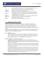
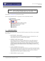
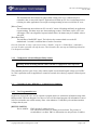
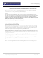
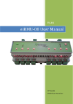
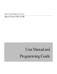
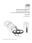
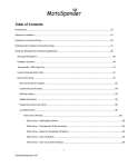
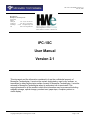
IPC-1SC User Manual, Version 2.1
Nov 23, 2009
Distributed by
Hemisphere West Europe Ltd
Ty Bryneirin
Sarnau,
Llandysul
Tel: +44 (0) 1239 654157
Ceredigion
Fax:+44 (0) 1239 654742
SA44 6QR
e-mail: [email protected]
UK
Web:www.hwiglobal.com
IPC-1SC
User Manual
Version 2.1
This document and the information contained in it are the confidential property of
Moneyflex Technologies. It must not be copied, duplicated or used in any manner, or
transmitted to others without prior written consent of Moneyflex Technologies. It must be
returned to Moneyflex Technologies when its authorized use is terminated. This
copyright extends to all the media in which this information may be preserved including
magnetic storage, optical storage, punched card, paper tape, computer printout or
visual display.
Copyright Moneyflex Technologies LLC 2008
Page 1 of 23
IPC-1SC User Manual, Version 2.1
Nov 23, 2009
Document change history
Version
1.0
1.1
2.0
Date
Sept-30-08
Oct-10-08
Jun-03-09
2.1
Nov-23-09
Comments
First release
VIP_Demo usage added
Redesign of kernel. New VIP_Demo functions
Extra programming information in Appendix
Controller 24 added
Disclaimer
Universal Serial Bus (USB) is a trademark of USB Implementer Forum, Inc. Microsoft Windows 98,
Windows Me, Windows 2000, Windows XP, Windows Vista are trademarks of Microsoft Corporation.
Multi-Drop Bus (MDB) and Internal Communication Protocol (ICP) are communication standards set by
National Automatic Merchandising Association.
Hardware and electrical connections given in this manual are for illustration purposes only. Moneyflex
Technologies LLC bears no responsibility of any damage or hazard that may cause.
Scope of this manual
This manual is to provide an overall view of the IPC products and IPC-1SC, in particular its architecture
and operations. Should you find any part of the manual is missing or mistaken, please revert to us at email
[email protected].
There are three more Moneyflex documents user will need before he / she can do the PC programming:
PG001 Programmer’s Guide
K1 Protocol Specification
Other suggested reading material:
FTDI driver documents at http://www.ftdichip.com/FTDocuments.htm
NAMA MDB / ICP v3.0 Specification
Product manual of the respective vending machine VMC
Warning: Do not connect power to device before finish reading this manual.
Copyright Moneyflex Technologies LLC 2008
Page 2 of 23
IPC-1SC User Manual, Version 2.1
Nov 23, 2009
1.0
INTRODUCTION
The Intelligent Protocol Communicator (IPC) series is a set of products designed to solve many of the
connection and interface problems found in nowadays automated payment systems. No matter your
monetary validating device utilizes an output format of a Simple Pulse, Dry relay contacts, a Parallel or
Binary output, a MEI™ EBDS serial port, an ITL SSP® port, a NAMA® MDB / ICP daisy-chained bus
system or the ccTalk bidirectional serial data line, IPC validates them all.
IPC consolidates all the status and events happening in your peripherals and reports them in a systematic
way back to your application. It utilizes the efficient K-1 Protocol for communication between your
application and IPC device. This unifies different communication standards found in different peripherals
into one easy to learn language.
IPC makes PC based vending machine, timed internet café and POS system work like a champ. With IPC
working in your system, you can take all the guess works out of your cash and cashless payment system.
1.1
IPC-1SC FEATURES
•
•
•
•
•
•
•
•
•
1.2
USB 2.0 full speed connectivity
Industrial standard controller chipset supports OSes such as:
Windows 98, Me, 2K, XP, Vista, Linux, Mac OS 8, 9, X and more
Serial COM port version is available as an option
SDKs and Drivers for software developers
Easy to use Moneyflex developed K1 Protocol
A patent pending PC Supervisory System that monitors your PC and OS so that they will not go
out of control
A programmable General Purpose Relay Contact for external device switching
A NAMA / ICP MDB Slave Cashless Device Simulator.
6 general purpose digital input lines and 1 digital output line for signal switching.
TERMINOLOGY
Below listed the terminologies and their explanation that are widely used in this manual.
MFX
PC
OS, OSes
Device
MCU, MCUs
Controller
Controller ID
=Short for Moneyflex Technologies LLC.
=Personal computer. An IBM x86 compatible machine.
=PC operation system, systems.
=IPC itself or a general USB Device.
=Micro-Processor(s) inside the device. Some devices may have multiple MCUs
running together in parallel for parallel processing. A single MCU may house
multiple Controllers within.
= An individual working unit that serves a particular function.
= An unique Address ID in Hex format that the Controller is defined to.
Copyright Moneyflex Technologies LLC 2008
Page 3 of 23
IPC-1SC User Manual, Version 2.1
Nov 23, 2009
User
K1 Protocol
NAMA®
MDB / ICP
MDB Host
MDB Slave
MDB Power
ms
USB-IF
1.3
= User’s PC application program. For better readability, this manual adopts a male
user gender and uses “he” instead of “it” to represent the program.
= MFX developed computer protocol adopted by IPC and other products.
= The National Automatic Merchandising Association
= Multi-Drop Bus / Internal Communication Protocol communication standard
developed by NAMA for use in vending and food service management industry.
= The MDB bus master where all the MDB commands initiate. Also known as the
Vending Machine Controller (VMC).
= Any MDB peripheral devices that talk to VMC in response to a VMC command.
= The voltage and current requirements of a MDB peripheral.
= millisecond(s). 1/1000th of a second.
= Universal Serial Bus Implementer Forum. www.usb.org
BACKGROUND OF IPC-1 & IPC-1SC
MDB / ICP is a communication standard widely adopted by vending machine manufacturers for
connection among bill acceptor, coin changer, card reader, etc to the host system (VMC). MDB
communication employs a 11-bit serial byte format. The Mode bit being the 9th bit (MSB) of the byte
dictates the direction of the message. This unique arrangement gives PC based serial ports a great
challenge to handle properly. Plus the 5ms response time requirement almost throws away all non-RTOS
systems.
In view of this, MFX developed the IPC-1 device to relief the above difficulties. The device gives user an
alternative way to work with MDB system. User can access to virtually all available MDB machines in
the market. There are two variants of IPC-1 device:
IPC-1, a MDB Host System
This model has a MDB Host port that is intended to connect to other MDB peripherals (slaves)
such as a bill acceptor and/or coin mechanism. All MDB commands / requests originate from
IPC-1. In another words, IPC-1 is a VMC replacement system that user can develop his own
VMC control software on a PC. IPC-1 is a MDB host to slave peripherals.
IPC-1SC, a MDB Slave - Cashless Device Simulator
This model shares same hardware as IPC-1 and loaded with a different firmware. Cable
WB02EB0 “MDB gender change and inline signal conversion harness” must be used together.
This product is designed to simulate a MDB cashless device in peripheral mode and communicate
with a VMC as a slave device.
On first use, user is required to setup a currency code, monetary scale & decimal point and other
configurations per his application. All information is stored in the device non-volatile rewriteable
memory (eprom). Once setup is done, IPC-1SC will communicate with a vending machine VMC
as a Level 01 cashless device.
The advantage of using IPC-1SC is that user can separate his cashless payment system from the
vending machine VMC system. In this way, user can run the cashless payment system on a PC
using his favorable cashless processing method (e.g. credit card processor or transaction agency).
After payment is confirmed by the processor, user just feed the approval information to IPC-1SC
and transaction will be taken in the VMC system. IPC-1SC greatly reduces the complexity of
implementation of cashless payment on a vending machine.
Copyright Moneyflex Technologies LLC 2008
Page 4 of 23
IPC-1SC User Manual, Version 2.1
Nov 23, 2009
In other words, IPC-1SC is a gateway between a traditional vending machine and a PC cashless
payment system.
WB02EB0, MDB connector gender change and inline signal conversion harness for IPC-1SC
This cable is designed to be used with IPC-1SC to convert MDB Host port into a MDB Slave port
and transmit power to the device.
2.0
ARCHITECTURE
An IPC consists of one or more CPUs working together, called the MCUs to achieve parallel processing
power. Each MCU has a number of different Controllers built into it. The Controller is the working unit
that user is dealing with. When user is talking to IPC, he is actually talking to an individual Controller by
using the K1 Protocol. The protocol enables user to specify which Controller the message is directed to.
Only the intended Controller with a correct ID number will reply to the request. On top of that, there is a
set of global commands that all Controllers will response to.
Each Controller has its own firmware known as the kernel. The kernel version can be retrieved by user at
anytime in his application. By checking the kernel version, user can know the updated information about
that particular Controller.
The USB controller used in IPC is a USB 2.0 full speed chipset conforms to USB 2.0 standard set by
USB-IF. Its main function is to inter-connect all MCUs reside within the device and distribute user
commands to/from each Controllers. A Serial COM port version is also available upon request.
2.1
KERNEL UPGRADE
Controllers’ kernel is flash ROM based. Occasionally MFX will release a new kernel version for a
particular controller for newer features. This kind of upgrade can only be conducted at MFX appointed
service site. Any attempt to tamper with the kernel program will lead to unit malfunction and void all
warranties.
2.2
PC INSTALLATION
The procedure of a PC OS (eg. Windows) registers a USB device and gets it ready for use is called
Enumeration. When a USB device plugs in to a USB port, OS receives the Vendor ID (VID) and Product
ID (PID) from the device. By sorting out these two IDs, OS loads the correct driver files (*.inf) / system
files (*.sys) / dynamic link library files (*.dll) / etc… The device is then assigned with a HandleID.
Application program can uses this HandleID to access the device.
Copyright Moneyflex Technologies LLC 2008
Page 5 of 23
IPC-1SC User Manual, Version 2.1
Nov 23, 2009
Warning:
Always use MFX provided device drivers for correct operation. Failure
to do so will result in installation failure and/or OS crashing.
Visit website www.moneyflex.net for latest driver options.
Upon successful enumeration, IPC is recognized as a Universal Serial Bus Controller.
2.3
CODE DEVELOPMENT
For complete programming details, please refer to PG001 Programmer Guide. Here are some examples
of K1 Protocol.
•
DEVICE RESET, Global command
This command resets all Controllers, including PC Supervisor within the Device. All
setup parameters will need to re-install after this command.
•
ADDRESS CLASH, Global command
This command requests all Controllers within the Device to show their existence by
replying with their respective Controller ID. In order to avoid multiple Controllers
sending their ID at the same time, IPC adopts a timing scheme for this. The elapse time
of each Controller to send its ID is based on its ID value multiplied by 5ms time. For
instance, a Controller with Controller ID 10 hex (16 dec) will reply a ‘10H’ at 16 x 5ms,
that is 80ms.
•
GLOBAL SUSPEND, Global command
This command puts most Controllers within the Device to stop their operations and enter
into suspend mode. Depending on the nature of the Controller, some Controllers will turn
off the attached peripheral or some will finish the current event before entering into
suspend mode. Refer to the respective Controller for details.
•
USER SUSPEND, Controller command
Copyright Moneyflex Technologies LLC 2008
Page 6 of 23
IPC-1SC User Manual, Version 2.1
Nov 23, 2009
This command puts the respective Controller into suspend condition. Depending on the
nature of the Controller, some Controllers will turn off the attached peripheral or will
finish with the current operation before entering into suspend mode. Refer to the
respective Controller for details.
3.0
CONTROLLERS OVERVIEW
IPC-1SC has the following Controllers built in:
[Controller ID]
09 (hex)
15 (hex)
24 (hex)
[Functions]
PC Supervisor / General Purpose Relay Contact
MDB Slave – Cashless Device Simulator
General Purpose I/O port GPIO #5: 6 digital inputs and 1 digital output.
3.1
Controller 09 (hex), PC Supervisor / General Purpose Relay Switch
3.1.1
Configured as a PC Supervisor
PC technology has evolved to an era that its unprecedented computing power and multi tasking ability are
useful in many critical and non-critical applications. Countless remote systems have been deployed in
unsupervised areas to run 24/7 unattended for a prolong period of time. It is not hard to realize that system
stability is the key concern. ATM terminals, pay-to-surf internet booths, electronic payment kiosks are
just a few examples of PC based systems. If these systems have more than desired down time due to OS
instability or the application is not to perfection, the purposes of the system are compromised.
The PC Supervisor Controller is a patent pending design (at print time) to safeguard of this irrational
moment to free your PC from going wild. Once the Controller detects a system hung up situation it will
send in a hard reset to your PC to reset it to its original state. This practically reduces down time to
minimum and saves up a lot of service expenses.
The work principle of the PC Supervisor is similar to a watchdog timer to govern the PC ping time. Once
setup, the PC must continue to ping the Controller within the programmed time interval. Otherwise it is
considered as a PC failure. The Controller will then send a reset signal to the PC down to the hardware
(on motherboard) level. During the reset period, the Controller will keep monitoring the amount of time
required for the PC / OS to reboot and resume normal operations. If the reboot time is longer than
expected, it is considered as a reboot failure. Another reset sequence will follow.
PC Supervisor has the following parameters to setup:
[WatchDog Timer]
Copyright Moneyflex Technologies LLC 2008
Page 7 of 23
IPC-1SC User Manual, Version 2.1
Nov 23, 2009
The maximum time interval between ping without causing a PC reset. 5 minutes may be a
reasonable value to start with. Some PC applications will hold up CPU for several minutes before
releasing it to other applications. Do not put too stringent timing at here to avoid false PC reset.
[Reboot Timer]
The maximum time interval between PC reset to PC restart, OS loading and finally to application
resume running. This timer stops once the normal ping resumes. If this timer expires, a PC reset
will happen. This is to safeguard of repeated reboot failure. 20 minutes may be a suitable value to
start with.
[Reset Hold Time]
The hold time of the RESET signal . The built-in relay actuates a hard reset to the PC
motherboard. 2 seconds is a nominal time of such a reset action.
Once the Controller is setup, it runs forever until a “Disable” setup or a “Global Reset” command is
received. No other operation will stop the timer. This Controller does not stop on Global Suspend and no
User Suspend is available.
3.1.2
Configured as a General Purpose Relay contact
Warning: Do not use Relay function when Controller is configured as a PC Supervisor
This controller provides a pair of a dry relay contact capable to switch small signal voltage up to 24VDC
2A. This is particular useful in application to control an external device having a separate (isolated) power
source.
3.2
Controller 15 (hex), MDB Slave – Cashless Device Simulator
3.2.1
User Programmable Area
On first use of a new IPC-1SC, user is required to program the device with below information using either
MFX provided VIP Demo Program 2.6 or above or user self developed program. All information is stored
in device rewriteable non-volatile memory. Data write endurance is 1,000,000 cycles and data retention
is longer than 40 years.
[DEVICE CONFIG]
Device Address.
VMC supports 2 cashless devices.
User can select between device address 0x10 and 0x60. The presence of
second address is to allow VMC to differentiate two unique forms of cashless
Copyright Moneyflex Technologies LLC 2008
Page 8 of 23
IPC-1SC User Manual, Version 2.1
Nov 23, 2009
devices coexist in a vending system. At press time, IPC-1SC supports device
address at 0x10 only.
Country / Currency Code – packed BCD.
The packed BCD country / currency code can be set in two different forms
depending on the value of the leftmost BCD digit.
If the leftmost digit is a 0, the International Telephone Code is used.
For example, the USA code is 0x0001.
If the leftmost digit is a 1, the latest version of the ISO 4217 numeric currency
code is used. For example, the code for US dollar is 0x1840 and for Euro is
0x1978. Use 0xFFFF for unknown country.
Scale Factor.
The multiplier used to scale all monetary values transferred between VMC
and IPC-1SC.
Decimal Places.
The number of decimal places used to communicate monetary values between
VMC and IPC-1SC.
All pricing information sent between VMC and IPC-1SC is scaled using the
scale factor and decimal places. This corresponds to :
[Actual Price] = P · X · 10 –Y
where P is the scaled value send in the price bytes, and X is the scale factor,
and Y is the number of decimal places. For example if there are 2 decimal
places and the scale factor is 5, then a scaled price of 7 will mean an actual of
0.35.
Application Maximum Response Time – seconds.
The maximum length of time IPC-1SC will require to provide a response to
any command from VMC. Default is 0x05. Do not change this without
thorough understanding of the VMC system.
Miscellaneous Options. Default is 0x00. Do not change this.
[DEVICE ID]
Serial Number.
User selected serial number in ASCII format. Fixed length to 12 characters.
Formatting (leading and/or trailing blanks) is the responsibility of user.
Software Version. User selected software version in packed BCD format. Fixed length to 2 bytes.
For example, software version 0120 is 0x01 0x20.
Copyright Moneyflex Technologies LLC 2008
Page 9 of 23
IPC-1SC User Manual, Version 2.1
Nov 23, 2009
3.2.2
Operation
At this moment, IPC-1SC simulates Cashless Device Feature Level 1 only.
IPC-1SC may be viewed as a state machine with the following states:
1)
2)
3)
4)
5)
RESET
DISABLED
ENABLED
SESSION IDLE
VEND
[RESET]
On VMC system power up, IPC-1SC responds to VMC poll at address 0x10 or 0x60 (depends on user
setting). VMC and IPC-1SC information exchange occurs.
[DISABLED]
IPC-1SC automatically enters this state from the RESET state when it has received setup information
from VMC. User should disable his cashless payment application on his PC.
Setup information includes:
VMC configuration:
Machine display number of Columns and number of Rows and display
format.
VMC ID:
Manufacturer Code, by EVA-DTS definitions.
Machine serial number, model number and software version.
VMC Max / Min Prices: Maximum and minimum scaled price.
[ENABLED]
In this state, IPC-1SC is ready to receive payment information from user. IPC-1SC will remain in this
state until
• a payment request is received from user (when it will enter the SESSION IDLE state),
• a “DISABLE” command from VMC (when it will return to DISABLED state),
• a “RESET” command is received (when it will enter the RESET state).
[SESSION IDLE]
When a new payment is required, user needs to send a “BEGIN SESSION” request to IPC-1SC to enter
this state. This indicates that IPC-1SC and user is available for vending activities. A “VEND” command
from VMC will cause IPC-1SC to leave the SESSION IDLE state and enter the VEND state when
products are selected and purchased.
Exceptions are when
• User sends a VEND DENIED or SESSION CANCEL message to stop a transaction due
to invalid payment or insufficient fund from patron.
• Patron uses the Cancel button on vending machine to terminate a transaction and VMC
sends a SESSION COMPLETE command to IPC-1SC.
Copyright Moneyflex Technologies LLC 2008
Page 10 of 23
IPC-1SC User Manual, Version 2.1
Nov 23, 2009
• Patron uses the Reject button on coin mechanism to terminate a transaction and VMC
sends a SESSION COMPLETE command to IPC-1SC.
These exceptions will cause VMC to end the [SESSION IDLE] state with a SESSION COMPLETE
command and returns to either [ENABLED] or [DISABLED] status.
[VEND]
This state is entered from the SESSION IDLE state upon reception of a VEND REQUEST command
from VMC. If the vend process is obstructed in any way that the desired product is not delivered to patron,
VMC will send a VEND FAILURE command to IPC-1SC and followed by a SESSION COMPLETE
command. User must reply with a REFUND COMPLETE or a MALFUNCTION ERROR message based
on the refund condition of user’s cashless payment system.
A complete list of commands / responses is listed in Appendix.
3.2.3
Auto Response and Event Polling
IPC-1SC is built with an auto response system to answer to certain VMC commands. These commands
are transparent to user except for first time use setup. Refer to Section 3.2.1. IPC-1SC responds to VMC
commands automatically and diverts important messages to user in an event history format. Thus user is
set free to the stringent communication requirement set by the MDB standard.
Important VMC commands or state change messages are delivered to user by an Event Poll system. User
should poll IPC-1SC for an event history at a moderate rate (e.g. every 100ms) to keep up with the events
/ state of the vending machine.
Event Poll system consists of a user poll command, a reply from IPC-1SC with an event counter and 12
event / state history records.
Some events are for information only, while some events are commands that user must answer. Refer to
Appendix and K1 Protocol specification Controller 15 for more information.
Note:
A reset caused by VMC will not clear Event History. This preserves an event history to user.
Copyright Moneyflex Technologies LLC 2008
Page 11 of 23
IPC-1SC User Manual, Version 2.1
Nov 23, 2009
USB side
MDB side
Poll
{ Event 1 }
User’s PC
application
IPC-1SC
Event Counter
Event 1
Event 2
Event …
…
Event 12
3.4
{ Event 2 }
VMC
{ Event 12 }
Controller 24 (hex)
This Controller provides 6 digital inputs divided into 2 bands. Input #1, #2, #3 belong to the Lower Band;
Input #4, #5, #6 belong to the Upper Band. This arrangement provides user a faster data retrieval time
than fetching all 6 inputs at once.
This Controller also features a digital output for signal switching.
[Digital Inputs]
Each inputs are Active Low logic and are internally tied to 5V via a 10K resistor. They are also
diode protected by device power rails. Input voltage < 3.5V (Logic=0) will set active state (bit=1).
A voltage > 4.5V or a floating input (Logic=1) will give an inactive state (bit=0). Each input
report is a rolling record of the past 1.60seconds. That means, any event happened in the past
1.60seconds would be logged and reported in a subsequent data retrieval command. Events
happened longer than 1.60seconds and have not been reported will be discarded.
Copyright Moneyflex Technologies LLC 2008
Page 12 of 23
IPC-1SC User Manual, Version 2.1
Nov 23, 2009
With this history reporting manner, user can easily monitor a fast changing digital signal at a
much moderate rate of data retrieval. Applications like selection buttons, mechanical / optical
switches or sensor inputs are made handy. Once data is retrieved, the event records are flushed.
Each input lines are sampled at every 25ms and 2 consecutive samples give one record (bit). Thus
each record equals 50ms. Both 25ms-period samples must be active (Logic=0) in order to set a
record active (bit=1). When both or either samples are inactive (Logic=1), the record is set
inactive (bit=0). A quick computation of 1.60seconds = 50ms x 32bits. In another words, every
input has 4 bytes of data to represent a history of 1.60seconds.
Record period = 1.60s; Record rate = every 50ms; Sampling rate = 25ms (debounce period =
50ms)
In a user data retrieval command, Lower Band will report Input #1, Input #2 and Input #3. Total
of 12 bytes of event data.
In a user data retrieval command, Upper Band will report Input #4, Input #5 and Input #6. Total
of 12 bytes of event data.
[Digital Output]
This output has a 10K ohm pull up resistor to internal 5V and a diode protection to device power
rails. It is controlled by a switching transistor capable of sinking 50mA current. General latency is
about 10ms. Max voltage = 40VDC or power positive, whichever lower.
This output line should only be used for signal switching only.
Refer to Hardware section for connection details.
Copyright Moneyflex Technologies LLC 2008
Page 13 of 23
IPC-1SC User Manual, Version 2.1
Nov 23, 2009
4.0
VIP Demo Program illustration
Click
In VIP Demo Program 2.6 or greater, MDB Cashless Device Simulator is added for Controller 0x15.
Use “Connect USB” to open a device handle to IPC-1SC.
Use “Scan Device” to show available Controllers in device.
Use “Auto Run” to start auto polling function.
Click on “MDB Cashless” box to open the Controller feature box.
For a new device, use “Set Cashless Config >” and “Set Cashless ID >” to program user data.
Refer to Section 3.2.1 for programming information.
Copyright Moneyflex Technologies LLC 2008
Page 14 of 23
IPC-1SC User Manual, Version 2.1
Nov 23, 2009
Use “Cntr Reset” to reset device and cause VMC to retrieve new Cashless Config and ID.
Use “Show VMC Config >” to show below VMC configurations:
• VMC Feature Level
01 = VMC is not capable or will not perform advanced features.
• Columns on Display
The number of columns on machine display. 00= display not available to user
• Rows on Display
The number of rows on machine display.
• Display information – xxxx xyyy
xxxxx = Unused
yyy = Display Type
000 = Numbers, upper case letters, blank and decimal point.
001 = Full ASCII
010-111 = Unassigned
Use “Show VMC ID >” to show below VMC identify:
3 bytes to represent
Manufacturer Code – ASCII
12 bytes to represent
VMC serial number – ASCII
12 bytes to represent
VMC model number – ASCII
2 bytes to represent
VMC software version – packed BCD
Use “Show Max / Min Price >” to show VMC maximum and minimum set price.
Use “Begin Session >” to initiate a new payment session. This command notifies VMC to allow patron to
make a selection, but do not dispense product until funds are approved.
Funds Available is a scaled value represents
• Lesser of the patron’s payment media or account balance or 0xFFFE units.
• Not yet determined – 0xFFFF.
After patron makes a selection, VMC will send a Vend Request, a scaled Vend Price and an Item
Number to IPC-1SC. VMC STATUS / MSG box will show Vend Request – Price=100 Item #=0
where Price is a scaled vend price of the selected product.
where Item # is the item number of the selected product. This number is defined by VMC
manufacturer, and set to 0xFFFF for undefined or not implemented.
Use “Vend Approved >” with correct Vend Amount to instruct VMC to dispense the selected product.
Vend Amount is a scaled amount deducted from the patron’s payment media or account. This may not
match the amount specified in the Vend Request command; it may be surcharged or discounted.
0xFFFF means an electronic token was used.
Note: User must use Vend Amount to update the credit on the screen. User must fill this field with used
amount for transaction.
Use “Vend Denied >” when payment is denied. Do not dispense any products.
Copyright Moneyflex Technologies LLC 2008
Page 15 of 23
IPC-1SC User Manual, Version 2.1
Nov 23, 2009
Use “Session Cancel >” to request VMC to cancel the session. This command is sent whenever payment
media is removed or a request for removal by patron (e.g. if a return button on vending machine is
pressed).
In a Vend Failure condition, user must send either a Refund Complete or a Malfunction message to
device to complete
Use “Refund Complete >” to send a Refund Complete message to VMC.
Use “Malfunction Err >” to send a Malfunction message and an Error Code to VMC.
Error Code – xxxx yyyy
xxxx
error types
0000:
Payment media Error1
0001:
Invalid Payment media1
0010:
Tamper Error1
0011:
Manufacturer Defined Error1
0100:
Communications Error2
0101:
Reader Requires Service2
0110:
Unassigned2
0111:
Manufacturer Defined Error2
1000:
Reader Failure3
1001:
Communications Error3
1010:
Payment media Jammed3
1011:
Manufacturer Defined Error
1100:
Refund error – internal reader credit lost
1101-1111:
Unassigned
1= Transient error – Send once
2= Non-Transient error – Send on every Poll to VMC until cleared. Device still functional.
3= Non-Transient error – Send on every Poll to VMC until cleared. Device not presently functional.
yyyy= Manufacturer defined subcode. Refers to VMC user manual for details.
Use “Display Message >” to request a user message to be put on machine display.
Message – ASCII characters. Formatting (leading and/or trailing blanks) is the responsibility of user. The
number of bytes must equal the product of Columns and Rows up to a maximum of 32 characters in
“Show VMC Config >”command section.
Duration = Display time in 0.1 second units.
Note: There is no guarantee user message will be displayed on machine screen for the specified amount of
Display time. Either VMC or user may overwrite the message before the time has expired.
Copyright Moneyflex Technologies LLC 2008
Page 16 of 23
IPC-1SC User Manual, Version 2.1
Nov 23, 2009
5.0
HARDWARE
An outlook of IPC-1SC device box.
IPC-1SC
5.1
LED Patterns
IPC provides 4 status LEDs for user to diagnose with his system. They are the:
[POWER]
[USB COMMS]
[IPC ACTIVITIES]
[MDB COMMS]
5.2
Turns on when device connects to power
Blinks when USB activities TX and RX are undergoing
Quick flashes when device sends or receives a Cashless device related
command on its MDB port
Momentarily on when Reset Supervisory system is resetting PC Flashes
@ 1Hz when Reboot Timer is ticking
Flashes when MDB TX and RX are undergoing
Electrical Hookups
Warning: Do not connect power to device before reading this section.
IPC-1SC has a POWER PORT, USB PORT, MDB HOST PORT, PC RESET PORT and ACCEPTOR
(GPIO) PORT.
Copyright Moneyflex Technologies LLC 2008
Page 17 of 23
IPC-1SC User Manual, Version 2.1
Nov 23, 2009
5.3
POWER PORT 12-34VDC
Warning: Do not connect power to this port when device is connected to MDB bus.
Otherwise, severe damage may result in the device, VMC and the power source.
This port is a center positive power plug with a 2.1mm center pin.
It is used during bench test when IPC-1SC is NOT connecting to MDB bus.
When device is connected to MDB bus, power is provided through the MDB port.
5.4
USB PORT
This is a USB 2.0, type B full speed port. Connects this port to a PC root hub or a USB hub. Use only
USB 2.0 capable cable. For less noise connection, always connects to PC root hub found on the back of
PC (direct to motherboard).
Copyright Moneyflex Technologies LLC 2008
Page 18 of 23
IPC-1SC User Manual, Version 2.1
Nov 23, 2009
5.5
ACCEPTOR (GPIO) PORT
This port has 6 TTL inputs and 1 transistor output.
Connector Pin-out:
Pin 1 – Ground
Pin 2 – MDB Power Positive
Pin 3 – Input #5
Pin 4 – Input #6
Pin 5 – N/A
Pin 6 – Output
Pin 7 – Input #1
Pin 8 – Input #2
Pin 9 – Input #3
Pin 10 – Input #4
Copyright Moneyflex Technologies LLC 2008
Pin 9 7 5 3 1
Pin 10 8 6 4 2
Looking towards Acceptor Port
Page 19 of 23
IPC-1SC User Manual, Version 2.1
Nov 23, 2009
5.6
MDB PORT
Connect cable WB02EB0 (MDB gender change and inline signal conversion harness) to this port to set
the IPC-1SC into a MDB Slave device.
IPC-1SC
To MDB bus
WB02EB0 cable
Inline Circuit Board
MDB
Port
Note:
WB02EB0 inline signal conversion harness must be installed with Inline Circuit
board at IPC-1SC MDB port side. Fail to do this may result in severe damage to
IPC-1SC and MDB system.
The MDB bus (wire) consists of power lines and signal lines. Power is supplied from VMC to peripherals.
Voltage ranges from 18VDC to 34VDC. In some unregulated host system, it may reach as high as 42V.
Signal lines consist of Transmit (TXD), Receive (RXD) and Signal GND.
Connector Pin-out:
Line 1 - DC Positive
Line 2 - DC Power Return
Line 3 - N/C
Line 4 - VMC Receive
Line 5 - VMC Transmit
Line 6 - Communications Common
6
5
4
3
2
1
Looking toward MDB port
5.7
PC RESET PORT
Molex P/N: 70553-0001; Mated with Molex P/N: 50-57-9402
This port provides a pair of relay contacts for PC Supervisory operation.
1. Use Moneyflex cable P/N: WA01BA0 (PC Reset Cable) to connect this port to user’s PC
motherboard RESET pins
2. and to RESET button leads of the computer case.
Below diagrams are for illustration only. Different PC motherboard manufacturers may have different
location for RESET pin headers. Refer to your motherboard manual for details.
Copyright Moneyflex Technologies LLC 2008
Page 20 of 23
IPC-1SC User Manual, Version 2.1
Nov 23, 2009
RESET pins
5.8
GENERAL PURPOSE RELAY CONTACTS
Molex P/N: 70553-0001; Mated with Molex P/N: 50-57-9402
When PC Supervisory function is not used, the PC RESET PORT can be used for general relay function.
Relay contacts are capable of 24VDC 1 AMP switching.
6.0
CE Declaration of Conformity
We certify that this product complies with the requirements of the EC Council Directive on
electromagnetic compatibility 2004/108/EC
Applicable Standards with amendments:
EN55022: 2006
EN55024: 1998 +A1: 2001 +A2: 2003
EN61000-3-2: 2006
EN61000-3-3: 1995 +A1: 2001 +A2: 2005
Electrostatic Discharge Precaution:
The normal function of the device may be disrupted by a strong electromagnetic
interference. If so, simply reset the device by cycling the power. Normal operation should
be resumed. If in such a case that the function could not be resumed, relocate the device
to another ESD-safe location.
Copyright Moneyflex Technologies LLC 2008
Page 21 of 23
IPC-1SC User Manual, Version 2.1
Nov 23, 2009
APPENDIX
Table of MDB commands to IPC-1SC responses and corresponding messages diverted to user. User is
required to feed certain information to IPC-1SC in order to complete VMC commands.
Bold= message originator
MDB communication
VMC Command
IPC-1SC Response
Setup/Config Data
Cashless Config Data
Request ID
Cashless ID
Reset
Reset
Poll
USB (or COM) communication
Event Poll
User Input
Reset
Reader Disable
Reader Disabled
Reader Enable
Reader Enabled
Reader Cancel
Cancelled
Reader Cancelled
Poll
Begin Session
Begin Session
Poll
Session Cancel
Session Cancel
Vend Request
Vend Request
Vend Denied
Copyright Moneyflex Technologies LLC 2008
Vend Denied
Page 22 of 23
IPC-1SC User Manual, Version 2.1
Nov 23, 2009
Vend Request
Vend Request
Vend Approved
Vend Approved
Vend Success
Vend Success
Vend Request
Vend Request
Vend Approved
Vend Approved
Vend Failure
Vend Failure
Refund Complete
Refund Complete
Vend Request
Vend Request
Vend Approved
Vend Approved
Vend Failure
Vend Failure
Malfunction Error
Malfunction Error
Vend Request
Vend Request
Vend Cancel
Vend Cancelled
Session Complete
End Session
Copyright Moneyflex Technologies LLC 2008
Session Complete
Page 23 of 23