1
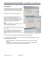
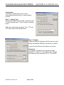
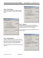
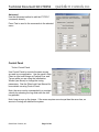
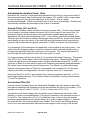
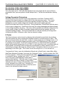
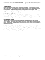
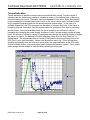
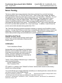
Technical Document:QCI-TD054 QuickSilver Controls, Inc. Date: 3 April 2009 www.QuickSilverControls.com Servo Tuning The factory default servo loop parameters have been optimized for a nominal load range (inertial mismatch up to 10:1) for each servo motor. Given a fairly tight coupling, the default tuning parameters meets the performance requirements of most systems. Generally, 19 out of 20 applications can use the factory default tuning parameters. Some applications require servo loop tuning to match the target system. One of the biggest challenges for a servo system is maintaining stable control in spite of a large mismatch between the motor’s rotor inertia and the load inertia of the system. The QuickSilver PVIA™ servo control algorithm can be tuned to provide stable operation over a very broad range. In addition, it can be tuned for precise control with mismatch ratios greater than 100:1. This Technical Document contains information necessary to properly tune QuickSilver control systems. It covers the PVIA servo control loop; commands associated with tuning, control loop parameters, and the effects of each parameter on motion. The document concludes with a section that provides tuning recommendations for specific applications. QuickControl Tools Primarily, two QuickControl tools are used for servo tuning. They are the Initialization Wizard and the Control Panel. Initialization Tools->Initialization Wizard As described in the User Manual, the Initialization Wizard is used to initialize the controller for such things as communications, error limits, and servo tuning. The servo tuning part of the wizard is documented here, while the rest of the wizard is documented in the User Manual. The file “Factory Default Initialization.qcp” contains two servo tuning commands. Control Constants (CTC) Filter Constants (FLC) CTC and FLC, by default, have “Default For Device” checked which means use the factory default servo tuning settings. You could edit the servo tuning parameters manually by un-checking this box, but we will show you how to use the Tuning Wizard instead. Property of QuickSilver Controls, Inc. Page 1 of 29 This document is subject to change without notice. QuickControl® and QCI® are Registered Trademarks of QuickSilver Controls, Inc. SilverLode™, SilverNugget™, SilverDust™, PVIA™, QuickSilver Controls™, and AntiHunt™ are trademarks of QuickSilver Controls, Inc.. Technical Document:QCI-TD054 QuickSilver Controls, Inc. Tuning Wizard The Tuning Wizard, by default, has the “Default Tuning Parameters” checked, which is the same as the FLC/CTC “Default For Device” checkbox. Uncheck this box to use the Tuning Wizard. The Tuning Wizard provides three methods or levels of tuning: Basic, Intermediate, or Advanced. Although they present three different interfaces, in the end, they edit the same two servo tuning commands (i.e. CTC/FLC). Basic The Basic tab allows the user to select from one of several standard system types. Press “Preset Tuning Param” and select one of the system types. Once you press OK, CTC and FLC will be set to factory defaults for the selected system type. These commands will also be sent to the selected servo. Use the Control Panel (see below) to test the new servo tuning parameters. For many applications, this all that is needed. If the servo is performing as required, go back to the Initialization Wizard to tab. • • Press “Download File To Device” to download the file to the servo’s non-volatile memory. Press Save to save the file to your PC (note if you are still using “Factory Default Initialization.qcp” you will be prompted to change the name). QuickSilver Controls, Inc. Page 2 of 29 Technical Document:QCI-TD054 QuickSilver Controls, Inc. Intermediate If the Basic method did not work, try the Intermediate method which is a 5 step iterative process. Step 1: System Type Much like the Basic method, Step 1 allows the user to select a system type. Think of this as a starting place. Select you system type and press Test. CTC and FLC will be sent to the selected servo. Step 2: Damper Adjust the Damper Frequency until the servo is quiet. Adjust the Damper Stiffness until the servo is stable. Use the Control Panel to test the servo in motion. Advanced The Damper Frequency is the geometric mean between Fv1 and Fv2. Press Advanced to change the frequency order and ratios of Fv1, Fv2 and Fa. QuickSilver Controls, Inc. Page 3 of 29 Technical Document:QCI-TD054 QuickSilver Controls, Inc. Step 3: Inertial Damper Increase the Inertial Damper to further eliminate noise. If the system is already stable, leave the default. Step 4: Stiffness Increase Stiffness (Kp) to reduce Position Error. The effects of Kp on Position Error is best seen by charting Position Error (see Control Panel). Note, increasing Kp too much will cause the servo to become noisy. Step 5: Holding Stiffness Increase Holding Stiffness (Ki) to reduce Position Error while the servo is holding (not moving). The effects of Ki on Position Error is best seen by charting Position Error (see Control Panel). Note, increasing Ki too much will cause the servo to oscillate. QuickSilver Controls, Inc. Page 4 of 29 Technical Document:QCI-TD054 QuickSilver Controls, Inc. Advanced Use the Advanced method to edit the CTC/FLC commands directly. Press Test to send to the commands to the selected servo. Control Panel Tools->Control Panel Use Control Panel to execute the same moves as used in your application. Use the panel’s Strip Chart to chart such things as Position Error and Torque while you are using the Initialization Wizard (see above) to change the tuning parameters. See the SilverLode User Manual for more details on using Control Panel. Note, the servo can be commanded to a constant velocity by releasing the Jog slider with the shift key pressed. Note, keep an eye on the torque. If the move requires more torque than the servo has, no amount of tuning will stabilize the system. QuickSilver Controls, Inc. Page 5 of 29 Technical Document:QCI-TD054 QuickSilver Controls, Inc. Control System Overview QuickSilver's PVIA™ Servo Algorithm Internal to the SilverLode servos is a unique servo loop algorithm called Position, Velocity Feedback/Feedforward, Integral, and Acceleration Feedback/Feedforward (PVIA). In the PVIA algorithm, position information is used to perform closed loop control of rotor position by detecting and correcting for errors in actual position versus the target position. Actual velocity and actual acceleration are calculated from the time history data of rotor position. Actual position, actual velocity, and actual acceleration data are passed in real-Time to the PVIA algorithm along with target position, target velocity, and target acceleration data (see diagram on following 2 pages). These variables are used in calculating the motor torque needed to correct any motor position error. The exact transfer function (when not limiting) is: QuickSilver Controls, Inc. Page 6 of 29 Target Position Target Velocity Target Acceleration Position Error Velocity - Twice Filtered Limiter (16 bits) (-2^15) < X < (2^15-1) Kvff Velocity Feedforward Gain Kaff Acceleration Feedforward Gain Velocity 2 Feedback Gain Kv2 Kv1 Velocity 1 Feedback Gain Velocity Mode (CLM) Proportional Gain Position Mode Kp Encoder Delta (this cycle) Target Delta (this cycle) Limiter (16 bits) (-2^15) < X < (2^15-1) Unit Delay Block Summation Block Ki/2^15 Integrator Gain Limiter Block Limiter (16 bits) (-2^15) < X < (2^15-1) Gain Block Limited Integrator Limiter -Tmax < X < Tmax Block Diagram Legend (120 usec per tick) Velocity Mode (CLM) Position Mode Sum of Non-Integral Terms Limiter (16 bits) -Tmax < X < Tmax QuickSilver PVIA™ Block Diagram Target Acceleration and Target Velocity are scaled such that the maximum values of each are represented by 2^15-1 Trajectory Generator VF = Fv2/2^15 Velocity - Once Filtered Second Velocity Feedback Low-Pass Filter 1024 KF = Fv1/2^15 Ka Acceleration Feedback Gain QuickSilver Controls, Inc. Property of QuickSilver Controls, Inc. Page 7 of 29 This document is subject to change without notice. QuickControl® and QCI® are Registered Trademarks of QuickSilver Controls, Inc. SilverLode™, SilverNugget™, SilverDust™, PVIA™, QuickSilver Controls™, and AntiHunt™ are trademarks of QuickSilver Controls, Inc.. (from motor shaft, 4000/rev) Position Acceleration Acceleration (filtered) First Velocity Feedback Low-Pass Filter AF = Fa/2^15 Acceleration Feedback Low-Pass Filter Technical Document:QCI-TD054 Torque Output Technical Document:QCI-TD054 QuickSilver Controls, Inc. Tuning Commands Primary Commands The following two commands set the primary tuning parameters. See the Command Reference for the specific details of each command. Control Constants (CTC) This command specifies values for the servo loop gain constants. Proportional (Kp) Velocity #1 Feedback (Kv1) Velocity #2 Feedback (Kv2) Velocity Feedforward (Kvff) Acceleration Feedback (Ka) Acceleration Feedforward (Kaff) Integrator (Ki) Filter Constants (FLC) This command selects the cutoff frequency for the velocity and acceleration filters. Velocity #1 Feedback Filter (Fv1) Velocity #2 Feedback Filter (Fv2) Acceleration Feedback Filter (Fa) CT2/FL2 SilverDust Rev 08 (SD08) SD08 includes alternative servo tuning commands: • Control Constants 2 (CT2) • Filter Constants 2 (FL2) Filter Constants 2 (FL2) changes the servo loops actual velocity and actual acceleration calculations from an "estimator" model to a more efficient "observer" model and enables the addition of a second acceleration feedback term. In simple terms, the "estimator" model calculates actual acceleration and velocity by differentiating the position, while the "observer" model calculates acceleration and velocity using commanded torque and integration. In both models, the actual velocity and acceleration are only approximations of the real velocity and acceleration. FL2 overrides any previous Filter Constants (FLC) command and enables the use of CT2's Acceleration 2 Feedback Gain (Ka2) parameter. CT2 overrides any previous Control Constants (CTC) command. Property of QuickSilver Controls, Inc. Page 8 of 29 This document is subject to change without notice. QuickControl® and QCI® are Registered Trademarks of QuickSilver Controls, Inc. SilverLode™, SilverNugget™, SilverDust™, PVIA™, QuickSilver Controls™, and AntiHunt™ are trademarks of QuickSilver Controls, Inc.. Technical Document:QCI-TD054 QuickSilver Controls, Inc. The Tuning Wizard automatically detects which set of commands is being used in the initialization file and changes the dialog boxes accordingly. Control Constants 2 (CT2) Proportional (Kp) Velocity 1 Feedback (Kv1) Velocity 2 Feedback (Kv2) Velocity Feedforward (Kvff) Acceleration 1 Feedback (Ka1) Acceleration 2 Feedback (Ka2) Acceleration Feedforward (Kaff) Integrator (Ki) Filter Constants 2 (FL2) Damping Factor (Kd) Stiffness Per Inertia Factor (Ksi) Anticipated Acceleration Factor (Kaa) Velocity 2 Feedback Filter (Fv2) Acceleration 1 Feedback Filter (Fa1) Acceleration 2 Feedback Filter (Fa2) Associated Commands The following commands set parameters associated with tuning. Anti-Hunt™ Constants (AHC) The Anti-hunt constants set the thresholds used to determine if the current position is sufficiently close to the target to allow the motor to enter into and remain in Anti-Hunt. The first parameter is the maximum error allowed in the Anti-Hunt before the unit will revert to normal closed loop operation. The second parameter is the maximum error allowed, at the end of motion, before going into Anti-Hunt. These two parameters should be set to zero before tuning the servo. This allows the true settling response of the servo to be monitored. Once the tuning is complete, the two parameters should be set back to there original values. S-Curve Factor (SCF) With the SCF command, the shape of the motion profile acceleration can be varied from a linear profile to a full S-curve profile. All basic motion commands incorporate the s-curve factor. This command can be set at any time except during a motion, allowing each motion profile to be tailored for the best shape. It is suggested that SCF be set to 0 (no S-Curve) during the initial stages of tuning. Once the system is stable with SCF set to 0, some S-Curve can be added as desired with minimal adjusted to the tuning parameters. QuickSilver Controls, Inc. Page 9 of 29 Technical Document:QCI-TD054 QuickSilver Controls, Inc. Torque Limits (TQL) This command specifies the torque limits for the different operating states of the servo. The two operating modes are Open Loop and Closed Loop with each mode having both a Moving or Holding condition state. The four parameters for the torque limits are Closed Loop Holding, Closed Loop Moving, Open Loop Holding, and Open Loop Moving. For most applications, the Closed Loop Moving torque limit is set to 100%, and the Open Loop Holding torque limit is set to 20%-30%. Normally, the Closed Loop Holding torque limit is set about 10% higher than the Open Loop Holding torque limit. Open Loop Moving torque is used less frequently, but is sometimes used, combined with a short Anti-Hunt delay to “snap” down a small residual error. See Torque Limits. Control Loop Mode (CLM) The CLM command closes the control loop around position or around velocity. When the servo loop is closed around motor velocity rather than motor position, the proportional gain (Kp) is ignored and therefore is disabled and the integrator acts on the difference in velocities between the target velocity and the actual velocity. These changes allow the servo to smoothly recover from a motion stoppage without overrunning the target velocity. Single Loop Control (SLC) The SLC command configures the servo to run in a single feedback control loop. All information for commutation, position, velocity, and acceleration control is derived from the internal encoder. If a motion is running, the Trajectory Generator must be shut down before executing this command. When entering single loop control, the servo sets the current target position to the actual position. The servo uses single loop control by default. The Dual Control Loop command is used for cases where external encoder position control is required. Switching between Single Loop and Dual Loop control usually requires changing the control loop tuning. QuickSilver Controls, Inc. Page 10 of 29 Technical Document:QCI-TD054 QuickSilver Controls, Inc. Dual Loop Control (DLC) The DLC command configures the servo to run in a dual feedback control loop. With a dual feedback control loop, the servo uses an external (secondary) encoder signal for position info. SilverLode motor commutation, velocity, and acceleration feedback information are still derived from the internal (primary) encoder, however moving and holding error limit flags are also based on the external encoder for triggering the Kill Motor Conditions. Anti-Hunt Mode uses the position error derived from the external encoder to establish when to move in and out of open loop holding torque. When precise position control is needed, an external encoder allows direct position control of the motor. Attaching an encoder directly to the driven device avoids the backlash and flexure present in the coupling between motor and the load. When using a linear slider for example, a linear encoder can be used for the external encoder signal. When entering dual loop control, the servo sets the current target position to the current actual position in order to prevent a sudden motion. The servo must be configured for closed loop control for this command to take effect. The servo uses single loop control by default, but the DLC command can be placed anywhere in a user program to change the servo to DLC. Executing a move with single loop control, before entering dual loop control, may be used to verify that the external encoder is connected and operational. The external encoder settings must be initialized before using this command. The Select External Encoder (SEE) command configures the servo for external encoder usage. The Control Constants typically need to be configured differently for dual loop operation. The default control constants are optimized for single loop operation. Motion parameters become related to external encoder counts rather than internal encoder counts. Only the position error term is derived from the external encoder, the velocity and acceleration terms are still calculated from the internal encoder. Typically, using an external encoder with twice the resolution would result in needing to reduce the proportional gain by a factor of 2. Typically the feedforward and feedback gains are set equal to each other. Some motions may require intentional under damping of the response, such as when moving liquids with a compliant pumping mechanism. Removing or reducing the feedforward term will introduce a moving error at velocity that will decay more slowly at the tail. This may help to prevent overshoot in a loosely coupled system. At the other extreme, heavy, tightly coupled loads may be moved with lower error if the feedforward acceleration term is increased to be larger than the feedback term; this causes the requested torque to jump in response to requested acceleration, even before any error has accumulated in the system. The use of the Strip Chart under the Control panel is a great aid in tuning. A clamp circuit is often useful while tuning a system, as this step often presents some of the highest acceleration and deceleration moves that the system will experience, as engineering attempts to determine the full capabilities of the system. QuickSilver Controls, Inc. Page 11 of 29 QuickSilver Controls, Inc. Technical Document:QCI-TD054 Overview of the Control System Parameters A good understanding of the control parameters and settings is useful when figuring what changes should be made to optimize the operation of the servo. QCI recommends that all users read the parameter descriptions and their functions in the control system before tuning the servo. The typical parameter ranges listed in the table below represents values that have been implemented in working applications and are to be utilized as a guide for user applications. Some applications may need values outside the typical range listed in the table. The table below lists user adjustable tuning parameters in the PVIA algorithm. Tuning Parameters Proportional Gain Velocity 1 Feedback Gain Velocity 2 Feedback Gain Velocity Feedforward Gain Acceleration Feedback Gain Acceleration Feedforward Gain Integrator Gain Velocity #1 Feedback Filter Velocity #2 Feedback Filter Acceleration Feedback Filter Symbol Kp Kv1 Kv2 Kvff Typical Parameter Range Native Units 40 – 400 0 5 – 50 5 – 50 Normal Units 40 – 400 0 5 – 50 5 – 50 Ka 0 – 200 0 – 200 Kaff 0 – 200 0 – 200 Ki Fv1 Fv2 0 – 2000 0 to 32767 0 to 32767 Fa 0 to 32767 0 – 2000 0Hz-200Hz 70Hz - 400Hz 30Hz - 2000Hz Optional tuning parameters for SD08. Tuning Parameters Proportional Gain Velocity 1 Feedback Gain Velocity 2 Feedback Gain Velocity Feedforward Gain Acceleration 1 Feedback Gain Acceleration 2 Feedback Gain Acceleration Feedforward Gain Integrator Gain Symbol Kp Kv1 Kv2 Kvff Typical Parameter Range Native Units 40 – 400 0 5 – 50 5 – 50 Normal Units 40 – 400 0 5 – 50 5 – 50 Ka1 0 – 200 0 – 200 Ka2 0 – 200 0 – 200 Kaff 0 – 200 0 – 200 Ki 0 – 2000 0 to 32767 Default: 21300 0 – 2000 0-100% Default: 65% Fsi=32768-Ksi Fsi=5-2758 Hz Damping Factor Kd Stiffness Per Inertia Factor Ksi QuickSilver Controls, Inc. 123 – 28672 Page 12 of 29 Technical Document:QCI-TD054 Anticipated Acceleration Factor Velocity 2 Feedback Filter Acceleration 1 Feedback Filter Acceleration 2 Feedback Filter QuickSilver Controls, Inc. Fv2 0-32767 Default: 25% of Ksi 4096-32767 Fa1 4096 to 32767 Fa2 4096 to 32767 Kaa 0-100% Default: 25% of Ksi 70Hz - 400Hz 0Hz – 2758Hz 0Hz - 2758Hz These parameters are used in the calculations of the PVIA algorithm that controls the position of the servo when in motion or stopped. Each parameter has its own individual influence on the servo operation, but most of the parameters work in conjunction with one another. For example, velocity and acceleration feedback filters have a frequency setting for rolling off high frequencies that may cause system instabilities and noise. Velocity and acceleration feedback serve to stabilize a control system, but they tend to force error into the system during non-zero velocity and non-zero acceleration stages of the move, respectively. To understand this, we will consider a constant velocity motion, using only a proportional term and a velocity feedback term. Assuming a fairly large system gain requiring only a small torque, a small position error, when amplified, would produce sufficient drive signal to operate the motor. However, when the velocity feedback term is included, the loop is not just looking at the error, but also the measured velocity times the velocity feedback term and the system gain. The velocity term, if compared to driving a car, acts to apply the brakes earlier and earlier for higher and higher velocities, to prevent going past the intended stopping point, where as the proportional term would not even get off the gas pedal until it had already passed the destination (ignoring it is still moving way too fast). However, with the two operating together (in the absence of feedforward), the “braking” of the velocity feedback term must be offset by a larger following error to produce more requested torque from the proportional term such that their sum produces sufficient output to drive the motor. As the error reduces, the proportional drive decreases. As the velocity slows, the braking action of the velocity feedback term decreases. If properly balanced the result is a smooth stop at the desired target. However, in the process of the motion, a following error was introduced, proportional to velocity! Adding an offsetting feedforward velocity term corrects the forced, but predictable, error that was caused by the velocity feedback; it does this without affecting the system stability. The result is a stable system with smaller error throughout its motion. The acceleration feedback is calculated so as to approximate a viscous inertial damper, that is a flywheel coupled to the shaft through a viscous coupling means. This type of a load produces a vibration dissipation effect. To understand the effect, consider a system running at speed. Both the motor shaft and the inertial load are spinning at the same speed. If a disturbance causes a decrease in shaft speed, the inertial load end up spinning at a higher speed, adding torque to offset a portion of the disturbance. Because of the viscous coupling between the shaft and the inertial load some shearing will occur which will dissipate heat. Now view a vibration on the shaft as a series of speeding up stages followed by slowing down stages; each time the speed changes, energy is dissipated in the viscous material. Removing the vibrational energy from the system damps the system and makes it more stable. For slower acceleration and decelerations, the viscous coupling does not significantly slip, and the damper appears to act more as a flywheel. QuickSilver Controls, Inc. Page 13 of 29 QuickSilver Controls, Inc. Technical Document:QCI-TD054 Now the mathematics of the corrective action of the acceleration term closely mimic that of a physical inertial damper. However, rather than actually accelerating a physical mass, which would reduce the torque available to the user load, the control acts to reduce the motor torque at those instants in time at which the simulated inertial load would be accelerating, and to increase the torque at those instants in time at which the simulated inertial load would be decelerating. The result is an improved system stability without the physical size, cost, or lost system torque required by a physical system. As with the velocity feedback term, the acceleration feedback introduces a predictable error which may be offset by adding an acceleration feedforward term. Further, the acceleration feedforward term may be increased to help command the motor to produce an expected needed torque in response to a commanded acceleration given a knowledge of the approximate inertia of the system. This allows a significant percentage of the system drive to be commanded using the prior knowledge of the system, rather than waiting for the system error increase to produce the needed torque. Note: Kv1 gain term adds in a singly filtered velocity estimate, where as Kv2 feeds in a doubly filtered velocity estimate. Most applications work well using only a Kv2 term. Some very light, very fast acting system may benefit by splitting the gains approximately 20% KV1, 80% Kv2 (with Kff typically being set to the sum of Kv1 plus Kv2. This configuration allows a portion of the faster responding Kv1 to act on the system. However, if driving significant inertial loads, torsional oscillations in the shaft may be accentuated by the lighter filtering and a high frequency oscillation may occur. Proportional Gain (Kp) Proportional gain (Kp) is the simplest component of the servo loop. Position error feedback enters the servo loop and Kp scales the error. The product of the error and Kp produces a torque that minimizes error. This concept is the basis of most servomechanisms. Thus, the larger the error grows, the more torque the motor produces. or The best analogy to Kp is a simple spring. If the servo were to be replaced by a spring, Kp would be the spring’s stiffness. If the shaft were rotated, the spring would be winding or unwinding. The more the shaft was rotated, the more the spring would fight back. The next Strip Chart plot (from the QuickControl Control Panel) demonstrates the effects of Kp. The filter constants are set at their default values and the control constants are set as follows: Kp Kv1 Kv2 Kvff Ka Kaff Ki QuickSilver Controls, Inc. = = = = = = = Page 14 of 29 1 0 0 0 0 0 0 Technical Document:QCI-TD054 QuickSilver Controls, Inc. The Strip Chart plots a 4000 count, 100 millisecond (ms) move with a 25 ms ramp time (MAT command). The channels plotted are Position and Target Position. The Target Position is where the shaft is supposed to be, and the Position is where the shaft actually is. Target Position Actual Position Kp = 1 A large amount of error is required to make the motor move. Setting Kp = 2 doubles the torque and produces the following profile. Target Position Actual Position Kp=2 Although less error is required to generate sufficient torque, the servo overshoots once the servo gets moving. The servo does not come back until enough negative torque is generated. Increasing Kp will continue to have this effect: QuickSilver Controls, Inc. Page 15 of 29 Technical Document:QCI-TD054 QuickSilver Controls, Inc. Target Position Actual Position Kp = 10 Using the spring analogy again, by increasing Kp, the spring stiffness is increased. Typically, Kp is increased to achieve the desired stiffness and reduce position error. Although the servo is moving to the target in a timely manner, there is noticeable overshoot. Thus, if Kp is large, the servo will start vibrating as it overcompensates for small errors. This is the same principle as a car with no shock absorbers. The springs work fine, but every time the car hits a bump, the car bounces several times. To eliminate the bounce, shock absorbers are added to the car. In the PVIA algorithm, the Velocity Feedback parameters (Kv1 and Kv2) act as shock absorbers. Velocity Feedback (Kv1 & Kv2) Velocity values are derived from the position information read every servo cycle, (120 microseconds). Velocity is calculated from the change in position each servo cycle. Velocity data is filtered by two cascaded low pass filters providing a once filtered value, Velocity 1, and a twice filtered value, Velocity 2. Both velocity values have a gain setting that is used to adjust the amount of velocity feedback. Velocity feedback is negative feedback used to dampen the servo control loop. Setting the velocity feedback gain values to zero removes all velocity feedback from the control loop. Kv1 is typically set to 0. Most applications have no need for a Kv1 greater than zero. Kv1 is only necessary for high frequency response applications (i.e. 10ms move). In these situations, the extra filtering done to calculate Velocity 2 does not accurately represent the load’s velocity. Kv2 is typically the only velocity feedback used. Kv2 is analogous to a shock absorber coupled with a spring. The more Kv2 increases, the more damping the shock absorber provides. With Kp only, the servo would oscillate to a stop during every move. Even the smallest amount of Kv2 adds noticeable damping to the system. The following plot has the same settings as the previous chart, except Kv2 = 1. QuickSilver Controls, Inc. Page 16 of 29 QuickSilver Controls, Inc. Technical Document:QCI-TD054 Target Position Actual Position Kp = 10, Kv2 = 1 The Kv2 parameter has a significant damping effect on the system. Setting Kv2 to 3 will provide even more damping. Target Position Actual Position Kp = 10, Kv2 = 3 Although the system has more damping, it is unable to match the velocity of the calculated trajectory. Velocity feedback subtracts some component of the velocity (Kv2 x velocity) from the calculated torque. As Kv2 increases, the velocity feedback will cause a greater velocity error in the system. To compensate for this, a Velocity Feedforward (Kvff) term is added to the system. Velocity Feedforward (Kvff) The servo contains an internal target generator called the trajectory generator. In real-Time, the servo calculates the motion profile defined by a command and its parameters. During each servo cycle, the target position is updated in the servo control loop. The trajectory generator also calculates a target velocity. The target velocity value is used to compensate for lag in position that is induced by the Velocity Feedback terms (Kv1 and Kv2). QuickSilver Controls, Inc. Page 17 of 29 Technical Document:QCI-TD054 QuickSilver Controls, Inc. Velocity Feedforward is a positive value used to anticipate the velocity necessary for a given move. Setting the gain value to zero eliminates the Velocity Feedforward term. Usually, this gain value is set equal to the sum of the Velocity 1 Feedback (Kv1) and Velocity 2 Feedback (Kv2) gain values. Kvff = 3 produces the following chart. Target Position Actual Position Kp = 10, Kv2 = 3, Kvff = 3 The actual velocity follows the desired velocity very well. To further reduce position error, Kp can be increased. With a dampener in place (Kv2), increasing Kp should not cause the system oscillation. In the next plot, the value of Kp is increased. For applications that require zero overshoot and faster response, Kvff may be slightly reduced to force a following error. This forces the servo to approach the commanded position from the starting side without overshooting. QuickSilver Controls, Inc. Page 18 of 29 Technical Document:QCI-TD054 QuickSilver Controls, Inc. The system responds very well with Kp=40. Target Position Actual Position Kp = 40, Kv2 = 3, Kvff = 3 Acceleration Feedback (Ka) The acceleration feedback value is derived from the Velocity 1 post filter value. And the Acceleration filter term. The Acceleration Feedback term functions as an electronic damper improving the overall system smoothness and decreasing the system settling time. Ka amplifies high rates of change of the velocity feedback. This counteracts any rapid changes in shaft velocity. Ka can be thought of as a virtual viscous inertial damper ( flywheel with a viscous coupling to to the shaft). The larger the value of Ka, the larger the virtual flywheel becomes. The higher the frequency settings for Fv1 and Fa, the stiffer the virtual coupling to shaft. A larger flywheel increases the virtual inertia of the system and resists rapid acceleration. Thus, Ka smoothes out the velocity ripple. Excessive Ka can introduce noise into the system as the individual encoder counts are emphasized. Excessive Ka combined with high Fv1 and Fa act as a large inertia with tight coupling and may cause high frequency instability, exhibited by a high pitch squeal. The relative values of Fv1 and Fa are also important. See Velocity Filters below. Ka is most useful when tuning out vibrations or resonance modes induced by system components (e.g. a belt drive). See the section on tuning belt drives at the end of this document for an example. Acceleration 1 Feedback (Ka1) (SD08) Acceleration 2 Feedback (Ka2) (SD08) Ka1 is the same as Ka. Ka2 is a second acceleration feedback term (second virtual viscous inertial damper). The acceleration for Ka2 is filtered by Fa2. Acceleration Feedforward (Kaff) The Acceleration Feedforward value is derived from the Velocity Feedforward value. It functions similarly to the Velocity Feedforward term by compensating for the position lag QuickSilver Controls, Inc. Page 19 of 29 Technical Document:QCI-TD054 QuickSilver Controls, Inc. induced by Acceleration Feedback term (Ka). Normally, Kaff is set equal to Ka, although it may be set slightly higher than Ka to assist with the acceleration of high inertial loads. Integrator Gain (Ki) The integrator parameter is the most important term for controlling steady state position error. The integrator works over time to eliminate position error. The longer there is position error, the larger the effect of Ki to get rid of the error. This term is commonly referred to as the “I” term in the traditional PID control loop. Unlike a PID servo loop, the PVIA integrator term can be increased greatly without causing hunting or oscillation. In the PVIA system, the velocity error, position error and the acceleration error are all integrated. This action keeps the system poles and zeros from moving as rapidly while still providing the increased gain. The integrator is also configured to reset to the level at which it may maintain linear operation through the limiters; any level higher than this merely adds to recovery time from a torque limiting process. This allows the motor to rapidly recover with minimum overshoot even when mechanically offset and released. The integrator gain should be set to zero when first tuning the other control constants. This allows a best effort tuning of the proportional, velocity and acceleration terms. Once these have been tuned, the Ki term may be increased until it causes overshoot, etc., with the value then backed down to a level to where those effects are avoided. This chart shows a 500 count move run with Kp set to 7 all other gains set to 0. Target Position Actual Position Kp = 7, all other K values (gains) = 0 The shaft never gets to the target position, because there is not enough torque generated by Kp to move the shaft into position. By using Ki, more and more torque will be added until the position error becomes zero. In the next plot, the integrator gain term is set to a small value, Ki = 5. QuickSilver Controls, Inc. Page 20 of 29 Technical Document:QCI-TD054 QuickSilver Controls, Inc. Target Position Actual Position Kp = 7, Ki = 5 The integrator gain greatly reduced the steady-state error. The product of Ki and Kp generally sets the steady-state accuracy of a system. In other words, if Kp is doubled, halving the Ki value achieves approximately the same amount of steady state error. A good starting point for determining the ideal Ki for a system is to take a look at the default Kp and Ki values. For example, if a custom tuned system has Kp = 200 and the default tuning parameters had Kp = 100 and Ki = 1000, a good starting value for Ki would be 500. Damping Factor (Kd) (SD08) Kd is a damping factor feeding back from the observer raw velocity into the observer raw acceleration, used to damp the 2nd order observer system. Setting this value to 100% (full scale native units of 32767) will approximate the response of the standard velocity filter system (overdamped). Reducing the value to approximately 65% of full scale makes the velocity estimate closer to critically damped, allowing the control loop to “see” the velocity sooner, which has the effect of increasing the phase margin of the system. Stiffness Per Inertia Factor (Ksi) (SD08) Ksi can either be thought of in terms of a “stiffness” factor between an internal position change and the internal raw acceleration estimate. The acceleration is integrated twice to calculate the “observer” motion such that the average calculated velocity corresponds to the average measured velocity. Ksi an also be thought of as a filter, Fsi where Ksi = 32768 – Fsi. Mathematically speaking, Fsi is the same as FLC's Fv1 for the same frequency roll off. Larger values of Ksi correspond to stiffer systems (i.e. thick shafts and low inertial loads) corresponding to faster (wider bandwidth) systems. When using QuickControl, the user may set Ksi in terms of Fv1 by selecting "Normal Units". QuickSilver Controls, Inc. Page 21 of 29 Technical Document:QCI-TD054 QuickSilver Controls, Inc. Anticipated Acceleration Factor (Kaa) Kaa allows the "observer" to anticipate the acceleration that is about to occur as the result of the commanded torque. Kaa should typically be between 10% and 80% of Ksi. Larger values of Kaa correspond to the expected response of a stiff system – that is a higher acceleration/bandwidth. When using QuickControl, Kaa is set as a percentage. QuickControl, automatically multiplies the percentage by Ksi at time of download. Velocity Filters (Fv1 and Fv2) Both Velocity Feedback values are filtered using two low-pass filters. The first one cascades into the second, providing a steeper frequency roll off on the output of the second filter. By adding this filtering, the velocity gains can be increased for greater damping capacity. In applications with large inertial mismatches (100:1 >), the velocity gains are increased greatly. The filters provide a means to stabilize the high gain servo control loop. As the control system would ideally act upon the velocity of the load (with any high frequency shaft torsions being ignored), high inertia loads are typically tuned with Fv1 and Fv2 at lower cutoff frequencies. A good example of this technique is the application of an equalizer to an audio system. If the upper half of the frequency range is reduced to minimum levels (reducing the high notes), a low pass filter has effectively been introduced into the system. The only sounds allowed to pass through the audio system would be the lower tones (i.e. bass). For a typical system, the first velocity filter (Fv1) is placed at the lowest frequency. The second filter (Fv2) is 2 to 5 times higher, with 3 times higher being typical. These tuned filters help reduce the high frequency resonance modes of widely mismatched systems (20:1 to 200:1). A good rule of thumb is to start with the upper cutoff frequency geometrically centered between the system’s anti-resonant and resonant frequencies. For example, a system with a large flywheel, setting these filters at 1000Hz is unreasonable; low hundreds of Hz for the upper frequency would be more appropriate, the lower frequency some 2 to 3 times lower. As the two filters Fv1 and Fv1 are cascaded, their roles are sometimes reversed, i.e. Fv1 is made higher rather than lower. This is done to allow more flexibility in setting ratios between Fv1 and Fa. See below. Acceleration Filter (Fa) Like the Velocity Feedback terms, the Acceleration Feedback term also has a low-pass filter that reduces undesired high frequency noise as well as affects the tuning of the system. Fa is typically set to about 5 times Fv1 (if Fv1 < Fv2) or 5 times lower (if Fv2 < Fv1). A physical viscous inertial damper has an optimal range of frequencies over which it aids damping; so does our simulated damper. This range is centered on the geometrical mean of Fv1 and Fa. The a larger ratio of Fv1 to Fa (taking the larger of the two over the smaller) produces a greater damping value (phase boost) up to a ratio of approximately 5:1, however, the wider the ratio, the more acoustical noise is heard. This is due to less filtering allowing more of the noise associated with individual encoder edges to pass through to the drivers. QuickSilver Controls, Inc. Page 22 of 29 Technical Document:QCI-TD054 QuickSilver Controls, Inc. Acceleration 1 Filter (Fa1) (SD08) Acceleration 2 Filter (Fa2) (SD08) Fa1 is the same as Fa. Fa2 is the filter feedback term associated with the second filtered acceleration term (second synthetic inertial damper term). Fa filters the acceleration used by Ka2. Voltage Dependant Parameters SilverLode servos have several control loop parameters in the Motor Constants (MCT) command that depend solely on voltage level of the external power supply. Thus, these parameters must be configured for the correct operating voltage of the servo. Incorrect initialization or power supply voltage level deviation can cause unstable operation. QuickControl takes care of most of the work. During initialization, QuickControl polls the servo for the current voltage level. QuickControl then sets the voltage dependant parameters based on the voltage sensed by the servo. If the servo will be operated at a different voltage than the current supply voltage, the Motor Constants voltage setting should be manually set to the expected operating voltage. This forces QuickControl to use the manually set voltage when configuring the Motor Constants, rather than the detected voltage. K Factor The SilverLode servo varies torque by changing the (estimated) current fed to the windings. The rate at which the servo changes the requested current is controlled by the K factor. This factor can be denoted by the term di/dt, or rate of current change per unit change of time. K is the fraction of the requested change permitted in each 120uS sample period, when the motor is operating at low speeds. As the motor speed increases, an internal calculation gradually adjusts the permitted change from K up to 100%, so as to allow the motor to produce torque at higher speeds. Increasing K factor’s magnitude corresponds to a faster maximum rate of current/torque change, and slower for a lower K factor. By default, K factor is set to 0.1 or 0.2, depending on the motor type. The K factor can be set as high as 1.0, or as low as 0.02. To access the K factor, open the Initialization Wizard tool in QuickControl, select Motor:Motor And Phase Advance Constants, then press the “Advanced” button. Another window titled “Edit K Factor” appears. Clicking the arrow expands the table of available K factors, ranging from 0.02 to 1. A lower K factor may help in stabilizing high inertia loads or systems with backlash. The lower rate of torque change helps minimize the rate of change of torque which translates into rate of change of acceleration, also known as jerk, allowed in the control loop. Internally K is increased as motor speed increases to allow the motor torque to be achieved at higher speeds. QuickSilver Controls, Inc. Page 23 of 29 Technical Document:QCI-TD054 QuickSilver Controls, Inc. Tuning Notes Proper tuning depends on the specific properties of the system. Tuning the servo a certain way for one system, may not work for another system. In order to help facilitate the tuning of different systems, several application specific recommendations are provided. These suggestions are meant to be a starting point. None of these recommendations are an end all solution, because all systems are truly unique. Inertial Ratios Up To 5:1 For a load inertia to motor inertia ratio of 1:1 to 5:1, the default tuning parameters should be sufficient. These have been optimized for each device for this nominal load range, assuming a relatively tight coupling (servo class coupler, or a stiff belt - Aramid type). Higher Inertia Ratios The servo can be tuned to handle huge inertial loads with mismatches of 1000:1 or even 3000:1 category. The limiting factor is not the control loop, but the electric motor’s maximum torque. At some point, the electric motor will just not have enough torque to move the mass in the desired time frame. For high inertia loads, the load inertia will dominate the response. Therefore, the velocity estimator should have a lower bandwidth (low Fv2), because fast variations seen at the servo are not good estimates of the actual load response. Reducing Fv2 reduces the high frequency gain of the system. This suppresses the high frequency resonance modes, allowing Kv2 to be increased to improve the low frequency damping of the system. QuickSilver Controls, Inc. Page 24 of 29 Technical Document:QCI-TD054 QuickSilver Controls, Inc. Torque Saturation Torque saturation is another common issue encountered while tuning. Common signs of saturation are the servo being unable to complete a motion in the required time or accruing excessive amounts of error. Saturation can occur because of two limits. Either the required torque exceeds the software based torque limits or the servo cannot output sufficient torque due to physical constraints such as the actual maximum torque output. In the case of a software torque limit, the TQL command can be edited to increase the limits. If the servo is limited by physical constraints, then the torque cannot be increased, other than by selecting another motor. If the total available power (torque at speed) is not sufficient, it may be increased by increasing the power supply voltage up to 48v if a lower supply voltage is being used. No amount of tuning or varying of parameters can change the physical amount of torque the servo can output. An example of torque saturating, taken with the Strip Chart tool, is shown below. The torque saturation is a result of the closed loop moving torque limit set to 25% (2nd Y axis, right hand axis). Notice how the position error (1st Y Axis, left had axis) deviates significantly from the near zero values when the torque saturates at the 25% mark. As this example shows, torque saturation greatly hinders the precision control. Thus, torque safety margin should always be included when selecting a motor type. QuickSilver Controls, Inc. Page 25 of 29 Technical Document:QCI-TD054 QuickSilver Controls, Inc. Anti-Hunt™ Settings Experiment with the Anti-Hunt settings to optimize operation. The typical Open to Closed value of 20 counts and Closed to Open value of 8 counts are a good start (assuming a 8000 count encoder). If normal operation involves overcoming the motor torque by hand or with a load (such as would happen with a gripper or going against a hard stop), then set up the servo to check holding currents before going into Anti-Hunt Mode. This makes the transition into and out of Anti-Hunt Mode smoother. Checking holding currents forces the closed loop torque to be less than the open loop torque setting before the servo enters Anti-Hunt Mode. Checking holding currents also forces the error to be less than the magnitude of the limit before AntiHunt Mode begins. This usually requires the load to settle down on its own, as even a slight error will cause the torque command to go to its limits when the integrator is on. This makes the servo go to zero error before the torque is reduced, meaning that the servo must delay entering Anti-Hunt Mode until the load has settled. Turning off the holding currents check bypasses the torque test, allowing the transition to Anti-Hunt Mode to be based solely on position error. Special Step and Direction Tuning For systems using step and direction inputs, the Anti-Hunt delay setting will delay the transition into the holding state to a time that is consistent with the step rate. For example, if the minimum step rate is 100 Hz, then the delay should be at least 10 or 20 milliseconds. This keeps the servo from transitioning between the moving and holding states while still moving. The velocity feedforward term must equal the sum of the two velocity feedback terms. Making it anything else will create a velocity dependent following error (if the feedforward is less) or leading error (if the feedforward is greater than the sum of the other two). Belt Driven Positioning Tables – Direct Drive The high torque of the servo coupled with its PVIA servo technology is ideal for direct drive belt applications. Direct drive belt applications have two challenges: high inertial mismatch and vibrations from flexure of the belt. QCI recommends tuning the high inertial mismatch first. After the high inertial mismatch is tuned, the vibration caused by belt resonance can be tuned out of the system. This is accomplished by increasing the Ka gain value to 5 or 10 times the default value and increasing the Fa filter to a frequency above the belt resonance (typically 1500 to 2000Hz). Operation from an External Encoder Tuning a the servo that is operating from external (secondary) encoder requires adjustments to the proportional gain (Kp). It must be properly adjusted in relation to the resolution of the external encoder. If the external encoder resolution is double (2X) the resolution of the internal encoder, then the default Kp value should be decreased by one half (0.5X). If the external encoder is one third (0.33X) the resolution of the internal encoder, then the default Kp value should be increased by a factor of three (3X.). QuickSilver Controls, Inc. Page 26 of 29 Technical Document:QCI-TD054 QuickSilver Controls, Inc. Tuning a 100:1 Inertial Mismatch-Advanced The following procedure describes how to tune a servo for high inertial mismatch by modifying the individual tuning parameters of the CTC and FLC commands (Tuning Wizard Advanced tab). High resolution, fast following applications require maximum bandwidth and gain, but no/minimal oscillations. When tuning the servo, it is important to keep the Velocity Feedforward (Kvff) term equal to the sum of the two velocity feedback terms (Kv1 & Kv2). The Acceleration Feedforward (Kaff) and feedback terms (Ka) should also be equal. 1. Determine Motion Profile To Be Tuned. Before beginning to tune the servo, determine the motion profile for the system. Absolute moves may be used to produce a fast move in one direction and a slow move in the other, while helping to ensure that hard stops are not hit. Make sure the move is within the torque limits of the servo. One of biggest problems with tuning a high inertial mismatch system is insufficient torque. While the servo is trying to move a very large load (100 times the rotor inertia), monitor the torque with the strip chart to make sure it does not max out. 2. Disable Anti-Hunt and Drag Mode Turn off Anti-Hunt Mode feature and Drag mode while performing the tuning process. AntiHunt and Drag Mode can hide clues needed for optimal tuning. 3. Start with the Factory Defaults Run the Initialization Wizard using factory defaults. 4. Set Ki to zero Start with Ki=0. It is important to optimize the system for the non-integrator terms first; we will add the integrator term in later. 5. Increase Kv2 and Kvff Increase both velocity terms to 10 times the default values. This factor of 10 corresponds to the natural frequencies of the system typically lowering by the square-root of 100 in a system with 100:1 mismatch. Adjust accordingly for other mismatch ratios. Test the move. Note any changes in operation or sound. If a high frequency screeching occurs in a low inertia system, lower the Kv2 and Kvff until the sounds subside. If excessive overshoot occurs, increase Kv2 and Kvff. Typical adjustments are by a factor of 2 (i.e. either divide by 2 or multiply by 2). Typically, Kv2 and Kvff are adjusted until there is some noise during the move, but not at rest. QuickSilver Controls, Inc. Page 27 of 29 Technical Document:QCI-TD054 QuickSilver Controls, Inc. 6. Reduce Fv1 and Fv2 Reduce Fv1 by 3 times the default setting, and set Fv2 to three times Fv1. The factor of 3 reduction corresponds approximately to the square-root of 10, where 10 was the shift in resonant frequency. We only shift by 3 - approximately the square root of 10 - to keep the filter point roughly centered at the geometric mean of the anti-resonant and the resonant frequencies. Example: Default: Fv1 = 209Hz, Fv2 = 209Hz Change to Fv1 = 70Hz, Fv2 = 210Hz This helps reduce the high frequency noise in the system. Test the move. Most noise should have quieted and the overshoot minimized. Keep decreasing the velocity filters until almost all the noise goes away. Remember to keep Fv2 three times greater than Fv1. Typically, Fv2 should be well above the total time of the system’s shortest move. For example, if a 100ms move is as fast as the servo will go (100ms = 10 rad/sec = 10/2π Hz ~ 1.6Hz), then Fv2 should be set to about 50Hz. Note that there is a tradeoff between bandwidth/response time and noise; a wider bandwidth corresponds to faster settling response (give adequate servo torque), but a wider bandwidth also allows more encoder noise (hearing each encoder increment pass through). 7. Adjust Ka and Fa Typically adjust Fa down by the same factor (i.e. 3) as Fv1 was adjusted. Ka may be adjusted up in value by approximately 10, as was Kv2. The combination of these changes makes the simulated inertial damper appear to have 3x lower critical frequency and about 10x the inertia of the default system. Increase Ka until it introduces noise and/or a squeal (too much gain), and then reduce by a factor of 2. The tolerable encoder noise level is an application dependent choice. Test the system for fast, medium and slow operation. 8. Iterate Kv2 and Kvff, Fv1, Fv2 With noise gone or greatly reduced, increase Kv1 and Kvff to decrease the overshoot. When noise and overshoot have been minimized, go to the next step. 9. Reduce Kv2 and Kvff by 10% Loosen up the system by decreasing both velocity terms by 10%. Test the move. Bring up the Strip Chart and observe the position error incurred from the motion. 10. Kp x 2 To decrease the Position Error, double the Position Gain. Test the move. Some oscillation may begin to occur. Bring up the Strip Chart and chart the position error and torque. Kp can be increased more if the position error is too great, but QuickSilver Controls, Inc. Page 28 of 29 Technical Document:QCI-TD054 QuickSilver Controls, Inc. watch the torque. If the torque saturates, no amount of tuning will allow the servo to provide more torque. 11. Set Ki and Reduce Kp, Kv2, Kvff by 25% A good starting place for Ki is a value that keeps the product of Ki and Kp the same as the factory default. In other words, if Kp is twice the default Kp, then start with Ki at half its default value Set the Integrator Gain and reduce all gains by 25% to provide system stability. Increasing Ki will make the system stiffer when holding a position. Increasing Ki too much will cause oscillation during motion. Test the move. The move should be stable. If excessive low frequency oscillation occurs, reduce Ki. 12. Save Results Record the results. Then download all the new control and filter constants to the servo. Reboot and test the servo again to verify that the correct parameters are being used. QuickSilver Controls, Inc. Page 29 of 29