1
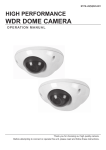
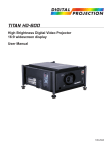
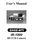
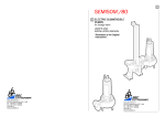
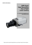
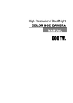
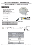
UNIQ
UM-400, UM-401
CCD Camera User's Manual
05-20-02
Table of Contents
Warning ....................................................................................................................................................
Precautions ..............................................................................................................................................
Limited Warranty .....................................................................................................................................
1
1
1
1. Introduction .........................................................................................................................................
1.1 General Description ...............................................................................................................
1.2 Features .................................................................................................................................
1.3 Applications ............................................................................................................................
1.4 CCD Imager Spectral Response Curve .................................................................................
1.5 Camera Specifications ...........................................................................................................
1.6 Camera Dimension ................................................................................................................
2
2
2
2
2
3
3
2. Camera Setup ......................................................................................................................................
2.1 Basic Camera Setup ..............................................................................................................
2.2 Camera and Frame Grabber System Setup ..........................................................................
4
4
4
3. Camera Functions ...............................................................................................................................
3.1 12-Pin Connector ...................................................................................................................
3.2 Shutter Speed Dial Switch .....................................................................................................
3.3 Normal and Asynchronous Capture Mode (NRM/ASM) .........................................................
3.4 Gain Control Mode .................................................................................................................
3.5 Gamma 1.0 and 0.45 Mode ...................................................................................................
3.6 Field and Frame Mode (FLD/FRM) ........................................................................................
5
5
5
5
6
6
7
4. Timing Signals .....................................................................................................................................
4.1 External Synchronization and Gen lock ...................................................................................
4.2 Integration ...............................................................................................................................
4.3 Strobe .....................................................................................................................................
8
8
8
9
5. Camera Malfunction ............................................................................................................................
10
6. Technical Support Information ..........................................................................................................
10
0
WARNING
TO PREVENT FIRE OR ELECTRIC SHOCK HAZARD,
DO NOT EXPOSE THIS CAMERA UNIT TO RAIN OR MOISTURE.
DO NOT ATTEMPT TO REMOVE CAMERA COVER OR MODIFY THE CAMERA UNIT,
WARRANTY WILL BE VOIDED.
PRECAUTIONS
Do dot attempt to disassemble, modify, or repair the camera. Contact UNIQ for help.
Do not point the camera at bright objects, such as the sun, for a long period. It may cause CCD blooming
and permanent damages.
Do not operate the camera beyond the temperature range. Avoid using the camera above 90% humidity.
Do not use unregulated power supply source.
Do not touch CCD glass cover with fingers or any hard objects other than professional glass cleaning
solvents.
Limited Warranty
UNIQ warrants to the original customer to be free from defects in material and workmanship for two full
years from the date of original purchase. This warranty covers failures or damages due to defects in
material or workmanship, which occur during normal use. It does not cover damages or failures, which
result from shipment, mishandling, abuse, misuse, or modification.
A Return Material Authorization (RMA) number is required prior to returning any UNIQ product for repair
or replacement.
This proprietary document may not be reproduced or photocopied without the consent of UNIQ. UNIQ
makes no warranty or assumes no responsibility for any errors, which may appear in this document.
UNIQ reserves the right to make changes without notice or obligation.
For immediate technical assistance, please call (408) 330-0818 or email to [email protected]
1
1. Introduction
1.1 General Description
The UM-400/UM-401 series is a low cost, high resolution, and standard EIA/CCIR CCD camera. It provides
excellent image quality with super HAD, on-chip micro lens and blemish free CCD imager. Different shutter
speed can be changed through rotary switch located on rear plate. AGC/MGC, Gamma 1.0/0.45, and
Frame/Field mode selections are also available on the rear plate. A 12-pin Hirose connector provides power,
HD/VD signals, and video output for the camera. UM-400/UM-401 is compatible with all-standard NTSC/RS-170
frame grabbers and TV monitors.
1.2 Features
• ½” Super HAD CCD Imager
• High resolution
768 x 494 (EIA); 752 x 582 (CCIR)
• Auto electronic shutter control
(1/60 – 1/100000 sec.)
• Fast Response time
• High sensitivity with micro lens
• 56 dB (AGC Off)
• AGC/MGC selectable
• Gamma 1.0/0.45 selectable
• Frame/Field mode selectable
*
1.3 Applications
UM-400/UM-401 applications include machine vision, automated inspection, monitoring, bar code reading,
biomedical imaging, non-contact measurement, microscopy, surveillance, and other scientific and industrial
applications.
1.4 CCD Imager Spectral Response Curve
*
Super HAD CCD is a registered trademark of Sony Corporation.
2
1.5 Camera Specifications
Model
CCD Sensor
Chip Size
Effective Pixels (H x V)
Unit Cell Size (H x V)
Scanning
Synchronization
TV Resolution
S/N Ratio
Min. Illumination
Video Output
AGC
Gamma
Frame Mode
Auto Electronic Shutter
Lens Mount
Operating Temperature
Power Requirement
Dimension
External
Synchronization
Low Speed Shutter
Long Term Integration
Weight
UM-400 (EIA)
UM-401 (CCIR)
½” Interline-Transfer Super HAD CCD
6.4 mm x 4.8 mm
768 x 494
752 x 582
8.4 µm x 9.8 µm
8.6 µm x 8.3 µm
525 TV lines, 2:1 Interlaced or
625 TV lines; 2:1 Interlaced or NonNon-interlaced
interlaced
HD: 15.734KHz; VD: 59.94.0Hz
HD: 15.625KHz; VD: 50Hz
H: 570 TV Lines;
H: 560 TV Lines;
V: 375 TV Lines
V: 450 TV Lines
56dB (AGC OFF, Gamma 1.0)
0.05 lux
1 V p-p, 75ohm (BNC or 12 pin Hirose)
AGC/MGC selectable
Gamma 0.45/1.0 selectable
Frame/Field Mode selectable
1/60 ~ 1/100,000 selectable
C-Mount
-10 °C ∼ +55 °C
12V DC, 210mA, 2.5W
50mm x 39mm x 83mm
Internal/External Auto Switch
2 FLD ~ 16 FLD (Optional)
1/30 sec. ~ 2 sec. (user control)
155 g
1.6 Camera Dimension
3
2. Camera Setup
2.1 Basic Camera Setup
For basic camera setup, as shown in Figure 1, one UM-400/UM-401 camera, one standard C-mount lens, one TV
monitor, one PS-12C power supply unit or equivalent, and one BNC cable (75Ω) are required. Make sure the
camera has the correct settings before powering up. See section 3 for details.
Figure 1. Basic Camera Setup
2.2 Camera and Frame Grabber System Setup
A basic camera and frame grabber system setup, as shown in Figure 2 below, requires a UM-400/UM-401
camera, a standard C-mount lens, a PS-12C power supply, a PC system and VGA monitor, a frame grabber or
interface card, and an external trigger device if necessary.
Figure 2. Camera and Frame Grabber System Setup
4
3. Camera Functions
3.1 12-Pin Connector
The 12-pin Hirose connector is located on the rear
plate of the camera. All ground signals on pin # 1, 3,
5, 8, 10, and 12 are common grounds. Although
+12 V DC input is recommended on pin #2, this
camera should withstand +12 V ± 1V input voltage.
Make sure to set the NRM/ASM switch to NRM
position on rear plate for external HD and VD
locking. Apply TTL signal on HD (pin # 6) and VD
(pin # 7) inputs if necessary, see section 4.1 for
details. Figure 3 below shows a top view of the 12pin Hirose connector.
Pin No.
1
2
3
4
5
6
7
8
9
10
11
12
Figure 3. 12-Pin Hirose Connector
Figure 4. Shutter Speed Dial Switch
3.2 Shutter Speed Dial Switch
Position
No.
0
1
2
3
4
5
6
7
8
9
Shutter speed dial switch is located on the rear
panel (Figure 4). For normal shutter speeds, it has 9
different shutter speeds to select from. Position # 0
is standard scanning speed, 1/60 second. As
“Position #” goes higher, the shutter speed goes
higher and the video becomes darker.
Description
GND
+12V DC input
GND
Video
GND
External HD
External VD/Strobe
GND
N/C
GND
Integration control
GND
Shutter
Speed (sec.)
1/60 (Off)
1/120
1/250
1/500
1/1000
1/2000
1/4500
1/6000
1/10000
1/31000
Note
TTL
TTL
TTL
Async
Capture (sec.)
1/60 – 1/100000
N/A
N/A
N/A
N/A
N/A
N/A
N/A
N/A
N/A
3.3 Normal and Asynchronous Capture
Mode (NRM/ASM)
NRM/ASM switch is located on camera rear plate.
Figure 5 shows all mode switch selections.
For normal operation, either with or without shutter
speed, NRM should be selected.
Set NRM/ASM switch to ASM mode for auto
electronic shutter control. This covers a shutter
range from standard 1/60 sec. to 1/100,000 sec.
5
Figure 5. Mode Switch
3.4 Gain Control Mode (AGC/MGC)
Automatic gain control (AGC):
AGC/MGC switch is located on the rear plate.
AGC factory setting is 2V for AGC control and 3V for AGC MAX control. Therefore, the maximum gain is about
18dB as shown in Figure 6 below. AGC setting cannot be changed through the rear gain potentiometer.
Manual gain control (MGC):
The manual gain control can be adjusted from 5dB to 18dB through the gain potentiometer on rear plate.
Note: 32dB gain can be obtained through custom orders.
Figure 6. AGC and AGC MAX Control Characteristics
3.5 Gamma 1.0 and 0.45 Mode
1.0/0.45 mode switch is located on rear plate. Gamma is the numerical value of the degree of contrast in a
television picture. Gamma correction is the system response modification by providing linear transfer
characteristic from the input to output. In general, circuit built into a TV camera to compensate for non-linearity
that exists in display tubes. If the camera is connected directly to a frame grabber, it is desired to set to Gamma
1.0. For direct connection to a TV monitor, gamma 0.45 is recommended, since TV monitor has a non-linear
correction. In general, gamma 0.45 is noisier than gamma 1.0, which is why gamma 1.0 is chosen for machine
vision applications. Gamma 0.45 is preferred when seeing video at low light level, which is common for
inspection by human eyes.
Figure 7. Gamma 1.0 and 0.45 Characteristics
6
3.6 Field and Frame Mode (FLD/FRM)
Field Mode:
Field/Frame mode switch is located on the rear panel. In field mode, two adjacent horizontal lines are combined
and scanned out as shown in figure 8 shown below. There is one line offset between odd field and even field.
The sensitivity in field mode is double for each field scanning (1/60 second). For any moving image capture, field
mode is recommended in order to avoid the smearing phenomenon. However, the resolution is only one field, not
full frame resolution.
Frame Mode:
In frame mode, every other horizontal line is scanned out; this is different from field mode as described above.
For odd field, line 1 is scanned out first. For even field, line 2 is scanned first. Each field has 1/30 second period.
Both odd and even field combined will form a full frame, a period of 1/30 second. For strobe, long-term
integration, and non-moving image capturing, frame mode is recommended. In order to obtain a full frame image,
a frame grabber must be applied to capture the image. It's difficult to distinguish the difference between field
mode and frame mode on a standard TV monitor. In frame mode, shutter function is disable.
Figure 8. Field and Frame Mode
7
4. Timing Signals
4.1 External Synchronization and Gen lock
The UM-400/UM-401 camera automatically locks to the external sync source. The external sync source must
match the camera HD and VD specification, which are 15.73KHz and 59.94Hz respectively. Both external HD
and VD are TTL level signals.
a) HD
H:
L:
Pulse width:
2.5V to 5V
0V or GND
5-50% duty cycle, see figure 10 shown below.
H:
L:
Pulse width:
2.5V to 5V
0V or GND
0.5-50% duty cycles; must be RS-170 format (odd and even fields).
b) VD
Figure 9. External Synchronization and Gen lock Timing
4.2 Integration
The UM-400/UM-401 camera can be integrated up to 2 seconds without severe noise or dark current effect.
Make sure the camera is set to frame mode before preceding any integration; this will ensure that there will be a
full frame video (both odd and even field). To start integration, pin #11 of the 12-pin connector must be connected
to GND or 0V. The integrated video will be shifted out following the next vertical drive after pin #11 goes back to
high or 5V level, as shown in figure 10 below. If a frame grabber does not capture the immediate two fields or
integrated video, the normal video (before the integration) will display again on the monitor.
Figure 10. Integration Control Timing
8
4.3 Strobe
Set NRM/ASM switch to ASM mode and make sure the FRM/FLD switch on rear panel is set to FRM mode in
order to achieve full frame resolution. The strobe application is similar to high-speed shutter application except
the strobe pulse must occur in the dark and no shutter is required. The advantage to use strobe is that a full
frame resolution of video will be obtained. This will not happen when high-speed shutter is applied; a progressive
scan or full frame CCD camera must be utilized. The relationship between external VD and strobe pulse signal is
shown in figure 10 below. Make sure to fire strobe pulse between 1H and 8H when internal VD is at 0V or GND,
where 1H = 63.5µsec. After strobe pulse is fired, camera will output only two vertical sync signals. The two sync
signals allow the user to capture the following valid fields. Therefore, the camera will not have any vertical sync
or video if there is no reset pulse on external VD pinout.
Figure 11. Strobe Timing
9
5. Camera Malfunction
WARNING: DO NOT ATTEMPT TO OPEN THE CAMERA HOUSING FOR TROUBLESHOOTING IN ANY
CASE WITHOUT THE CONSENT OF THE FACTORY.
Camera malfunction rarely happens. In case camera malfunctions, the following troubleshooting procedures
would help to minimize the problem; it definitely helps the user to find out the actual problem and may save a trip
for sending the camera back to the factory.
First of all, disconnect the 12-pin Hirose power connector and BNC cable from the camera unit. Make sure there
is nothing connected to the camera at this time.
Check the 12V DC power supply at the 12-pin connector cable and make sure it does provide the right voltage to
the 12-pin connector.
Make sure to set the camera shutter dial switch back to 0 position and NRM/ASM to NRM location.
If frame grabber was connected to the camera, disconnect it.
Now, power up the camera, and connect it to a TV monitor with a BNC cable. Make sure the monitor and BNC
cable are good. Point the camera at a bright scene without a lens on, a blank or bright display should be seen on
the TV monitor. Covering the CCD camera with hand or lens cap should see a dark video. If no video occurs,
most likely the CCD camera is damaged. Consult the technical support at the factory.
If there is video but it is not clean or bad, it is possible that the CCD imager glass is dirty because of the dirt on
CCD glass surface or the CCD camera is partially damaged. Use high-pressure air to blow the dirt away if the
CCD glass is not clean. If the problem still exists, contact the UNIQ technical support for help.
If there is video on TV monitor but not with a frame grabber, most likely the problem is from the frame grabber's
software or hardware. Consult the frame grabber factory for further details. If a lens is used, make sure the iris is
wide open.
6. Technical Support Information
For technical assistance, contact UNIQ Technical Support or Applications Engineer at
Phone:
(408) 330-0818
Fax:
(408) 330-0886
Email:
[email protected]
Company contact information:
UNIQ
3342 De La Cruz Blvd.
Santa Clara, CA 95054 USA
Phone:
(408) 330-0818
Fax:
(408) 330-0886
Our web site:
Sales Inquiries:
Technical Support:
www.uniqvision.com
[email protected]
[email protected]
10