1
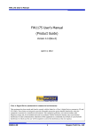
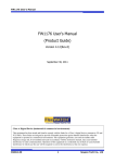
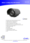
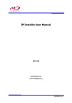
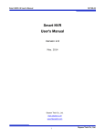
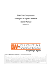
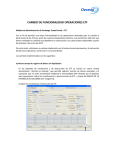
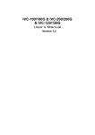
MDR-iVS01 User’s Manual Part 1 MDR-iVS01 User’s Manual Part 1 (Product Overview) MicroDigital Inc. www.microdigital.co.kr 1 MicroDigital Inc. MDR-iVS01 User’s Manual Part 1 Contents 1. 2. 3. Product Overview ....................................................................................................................... 3 1.1. MDR-iVS01 ......................................................................................................................... 3 1.2. Key Functions of MDR-iVS01 ............................................................................................. 3 1.3. Technical Specification of MDR-iVS01 ............................................................................... 4 1.4. MDR-iVS01 Packing List .................................................................................................... 6 Hardware Description ................................................................................................................. 7 2.1. MDR-iVS01 Front Panel View ............................................................................................ 7 2.2. MDR-iVS01 Rear Panel View ............................................................................................. 8 MDR-iVS01 H/W installation and basic setup ............................................................................ 8 3.1. Before installation, .............................................................................................................. 8 3.2. Factory Default Condition ................................................................................................... 9 3.3. MDR-iVS01 H/W Installation............................................................................................... 9 2 MicroDigital Inc. MDR-iVS01 User’s Manual Part 1 1. Product Overview 1.1. MDR-iVS01 MDR-iVS01 server is 1ch Network Video Server, which transmits digital images captured by Analog CCD camera over the Internet. So users can view real-time live images over the Internet at anytime and anywhere using the standard web browser such as MS Internet Explorer or Netscape Communicator. There is no need other specific software to view real-time live images over the Internet. MDR-iVS01 server is stateof-the art device and leads new generation of monitoring and security solution. Picture 1 : MDR-iVS01 1.2. Key Functions of MDR-iVS01 1. Standalone device built-in web server 2. Max 30 fps transmission speed on TCP/IP network 1. 10M/100M Auto Sensing Ethernet 2. Effective Bandwidth & Bit-rate Control by H.264 3. Built-in 2 way Audio transmission (1ch A-in, 1 A-out) 4. Supports Dynamic IP users by www.ipcctvdns.com server 5. Supports Sensor Input, Digital Output 6. Supports Transparent mode 7. Encryption function by user authentication 8. Image transmission function via FTP, Email 9. Supports Various PTZ (Pan/Tilt/Zoom) Devices 10. 1CH V-out for displaying on analog monitor 3 MicroDigital Inc. MDR-iVS01 User’s Manual Part 1 1.3. Technical Specification of MDR-iVS01 Model Name Hardware Video compression Resolution Frame rate (each channel) Video Streaming MDR-iVS01 32bit Embedded CPU Flash 8Mbytes /SDRAM: 128Mbytes Linux version 2.6.14 operating system Battery backed up real-time clock Motion JPEG H.264 NTSC: 720 x 480,704x480,352x240,176x112 PAL: 720 x 576, 704x576,352x288,176x144 Motion JPEG: Up to 30/25 fps at D1 (Secondary Stream at QCIF) H.264: Up to 30/25 fps at D1 (Secondary Stream at QCIF) Motion JPEG and H.264 Dual Streaming (Simultaneously) Controllable frame rate and bandwidth LAN interface Compression levels: 6 (Motion JPEG) / 6 (H.264) Color: color, black & white 8 bit PCM(G.711-u-low), Sampling rates 8KHz, Mono Audio 1ch in & 1ch out 10/100BaseT Ethernet auto sensing Alarm I/O Interface 1 Photo-coupled inputs and 1 Relay output Video Input 1 Channel Composite Video Input Video Output 1 loop through analog video outputs Two serial ports for console, modem(PSTN & GSM), serial input/output device, PTZ COM Port is RS-232, AUX port can be configured as RS-485 Max Baudrate: 115200 bit/s Multi user level protection for camera access, PTZ, Alarm I/O Up to 15.5M memory for Pre/Post alarm buffer e-mail, FTP, alarm Buffer by event or schedule IP notification, Alarm Notification to e-mail, CGI Call by event or schedule Accuracy: 12x12=144 blocks Motion Sensitivity : -100 ~ 100 : 100 is hypersensitive Transmit Serial input data transfer with Video IP notification by e-mail Configurable by serial, web or telnet Remote system update via telnet, FTP OR web browser. SMPS input: 100~240VAC, 300mA Output: DC 12 Volt, 800mA Image setting Audio Serial Interface Security features Advanced Service Built-in Motion detections Others Management PWR Supply PWR Consumption DC 12Volt 500 mA Operating Environment Temperature: 32° ~ 122°F (0° ~ 50°C) Humidity: 20 ~ 80% RH(non-condensing) 4 MicroDigital Inc. MDR-iVS01 User’s Manual Part 1 Users 16 simultaneous users Installation, management and maintenance Installation CD and web-based configuration Firmware upgrades over HTTP or FTP , firmware available at www.microdigital.co.kr Video access from Web browser Video access from Web browser Minimum Web browsing requirements Supported protocols Applications Pentium III CPU 500 MHz or higher Windows XP, 2000, NT4.0*, Internet Explorer 6.x or later HTTP, TCP/IP, FTP, Telnet, RARP, PPP, PAP, CHAP, DHCP, SMTP client(e- mail), NTP, Java, RTP/RTSP, UPnP MicroDigital CMS, MicroDigital Software NVR (MDR-IS004) Table 1 : MDR-iVS01 Specification 5 MicroDigital Inc. MDR-iVS01 User’s Manual Part 1 1.4. MDR-iVS01 Packing List MDR-iVS01’s packing box includes the following items. MDR-iVS01 1ea Power Supply Unit (Power Cable & SMPS DC12V 0.8A Adapter) 1ea Direct Cable 1ea CD (User’s Manual, Installation wizard, Picture, etc) 1ea MD-PWE Adapter (To supply to power through the LAN Cable.) Option MD-POE Adapter (To supply to power through the LAN Cable From POE Router.) Option Table 2 : MDR-iVS01 Packing List Please check all the listed items are included in your package. For any missing items, please contact your local distributor. 6 MicroDigital Inc. MDR-iVS01 User’s Manual Part 1 2. Hardware Description 2.1. MDR-iVS01 Front Panel View Picture 2 : MDR-iVS01 Front Panel A B C D E Name F G Description A Power B Grounding Connector C Factory Default Button D LAN E COM F POWER LED (RED/GREEN) G LAN(Tx/Rx) LED (RED/GREEN) Power input ports for DC 12V 0.8A [SMPS]. Ensure to use the original power supply unit from the package. Grounding Connector This button can reset the factory default settings at the system. Especially when a user lost his/her admin-password, or when it got any uncertain faulty operation. - After reboot the system, wait until hearing two times of beep sound. - Keep pressing FD button for 5~10 seconds until hearing three times short beep sound. ACT LED blinks during the process. The system will reboot automatically when it’s completed. LAN Port for 10/100M Base T Auto sensing. RS-232 ports for Serial input device, Modem or Console (HyperTerminal connection). RED light – It blinks RED when power on. GREEN light – It blinks GREEN when IP setup is done. RED light – It blinks RED when data is being transmitted on the connected LAN port GREEN light – It blinks GREEN only when LAN port is connected without data transmission. Table 3 : MDR-iVS01 Front Panel Description 2.2. MDR-iVS01 Rear Panel View 7 MicroDigital Inc. MDR-iVS01 User’s Manual Part 1 Picture 3 : MDR-iVS01 Rear Panel View A B C Name D E F Description A Video In BNC cable port for 1ch Video input. B Video Out 1ch Video Output port displaying on Analog Monitor. C MIC, SPK 1ch Audio Output and Input D RS485 RS-485 Ports for PTZ E DI (SENSOR) Signal input ports for sensor and contact. F DO (ALARM) Signal output ports for alarm and light. Table 4 : MDR-iVS01 Rear Panel Description 3. MDR-iVS01 H/W installation and basic setup 3.1. Before installation, 1. Read carefully User’s Manual 2. Check-out if the power source is stable or not at the environment. 8 MicroDigital Inc. MDR-iVS01 User’s Manual Part 1 3.2. Factory Default Condition The following table shows the factory default condition. Please refer to this when you need to change the values on admin menu. Factory Default Condition Admin ID root Admin password root IP address 10.20.30.40 Network mask 255.255.255.0 Gateway 10.20.30.1 Table 5 : Factory Default Condition Factory default Admin ID and Password are all lower case letters. You can change the password with Capital letters. 3.3. MDR-iVS01 H/W Installation Following steps show the physical installation process for MDR-iVS01. 1. Install CCTV cameras at each required position. 2. Connect BNC cable between CCTV camera’s V-out and MDR-iVS01’s V-in. 3. Connect a LAN cable at MDR-iVS01 in your local network. 4. Connect the power cable at MDR-iVS01. After that, you need to follow the steps below. 5. First, Network Configuration by MD-installer. 6. Second, Camera Configuration by MD-installer or admin-menu. 7. Third, Service Configuration by MD-installer or admin-menu. For IP setup, refer to “Chapter 2.Network Configuration” on User’s Manual Part2. 9 MicroDigital Inc.